

Page 1

FieldServer Technologies
A Sierra Monitor Corporation Company
1991 Tarob Court, Milpitas, California 95035 USA
Phone: (408) 262-2299
Toll Free: (888) 509-1970
Fax: (408) 262-2296
Email: support@fieldserver.com
Web Site: www.fieldserver.com
FS-X20 Series
FS-X20 Start-up Guide
APPLICABILITY & EFFECTIVITY
This manual provides instructions for the following FieldServer products:
Description
FS-X20 Series FieldServer
The instructions are effective for the above as of February 2005
Instruction Manual Part Number: T17005
Applicability and Effectivity
Rev. D
Page 2

FS-X20 Series FieldServer Start-up Guide Table of Contents
TABLE OF CONTENTS
1.
PRE-INSTALLATION CHECK LIST ............................................................................... 2
1.1.
Supplied equipment ................................................................................................... 2
1.2.
Start-up...................................................................................................................... 2
2.
PRODUCT DESCRIPTION ............................................................................................. 3
2.1.
Specifications............................................................................................................. 3
2.2.
Mounting.................................................................................................................... 3
2.3.
Wiring ........................................................................................................................ 3
2.4.
Supplied Connector Kit (FS-8915-11) ........................................................................ 5
3.
OPERATION................................................................................................................... 8
3.1.
Install and Run the Utility Software............................................................................. 8
3.2.
Use PING to Identify the FieldServer on the Network................................................. 8
3.3.
Connect using “Remote User Interface” (RUINET)..................................................... 8
3.4.
Use RUINET to change the FieldServer IP Address and Network.............................. 8
3.5.
Upload the Default Configuration ............................................................................... 8
3.6.
Change the Configuration File to Meet the Application............................................... 9
3.7.
Download the Updated Configuration File.................................................................. 9
3.8.
Test and commission the FieldServer ........................................................................ 9
APPENDIX A. LIMITED WARRANTY ...................................................................................10
APPENDIX B. LED FUNCTIONS ..........................................................................................11
Table of Contents
Page 3

Start-up guide
1. Pre-Installation Check List
1.1. Supplied equipment
The following components are supplied:
• FS-X20 Series FieldServer, loaded with
Modbus RTU driver, SMT Ethernet
driver and any other drivers ordered.1
• FS-X20 Series Start-up Guide (T17005)
• FieldServer Configuration Manual
(T17003)
• FieldServer Utilities Manual (T17009)
• Driver Manual(s) specific to all Drivers
ordered with the FieldServer.
• Utility CD – note that the Utilities support
the following platforms only:
• Windows XP
• Windows 2000
• Windows NT
• Windows 98
• Any additional Diskettes related to
special files configured for a specific
FieldServer.
• Additional components as required -.
See Driver Manual Supplement for
details
• An accessory bag consisting of the
following: :
• DB9F/RJ45 Connection Adapter.
(Part Number FS-8917-02)
• 7-ft Cat5 cable with RJ45
connectors at both ends (Part
Number FS-8915-10)
• RS-232 Mini Tester, 25-pin (Part
Number FS-8915-13)
• RS-485 connector (Part Number
FS-SPA59137)
• Set of four different connectors
DB9M, DB9F, DB25M, DB25F (Part
Number FS-8915-11)
• Power Supply
• Connector for power (SPA59136)
Driver Manual(s) and the Utilities
manual.
•
• The power socket mates with a
pluggable terminal block, connector, that
is supplied separately (SPA59136). The
terminal block is manufactured by
Phoenix Contact, model MSTB, (PN
1754465), No.30-12 AWG, 5-7 in/lbs
torque.
•
• USE COPPER CONDUCTORS ONLY
• Select an external power supply certified
for safety, for the correct destination
country and an output rating, which is
considered a NEC Class 2 circuit or is a
SELV Limited power source with the
following ratings:
• 9-30 VDC, 1A; OR 24 VAC, 50/60Hz,
0.5A
•
• INPUT VOLTAGE SPECIFICATION
• 24 VAC FLOATING
• Using a grounded VAC will cause
irreparable damage to the product.
•
• The operating environment for the
product is 0 to 60°C (32 to 140°F).
•
•
•
•
1.2. Start-up
• Read this Start-up Guide in conjunction
with the Configuration Manual, the
1
Note that a default configuration file has
already been loaded onto the FieldServer.
Check the Driver Manual and the FieldServer
Configuration Manual for further information on
this file.
Page 2 FS-X20 Series FieldServer Start-up Guide (07-2005)
Page 4
Start-up guide
2. Product Description
2.1. Specifications
Power requirements (power supply is external)
X20 power supply P/N 69155
Input voltage: 9-30VDC, 8W; 24VAC Floating. Voltage variation of ±10% tolerated.
Output voltage / current: 24VDC @ 0.5A
Physical Dimensions(excluding the external power supply)
(WxDxH): 3.82 x 4.08 x 1.7 inches (9.70 x 10.36 x 4.31 cm)
Weight: 0.8 lbs. (0.36 Kg)
Available Ports
1 x RJ45 / RS-232 serial connector
1 x RS-485 serial connector
1 x RJ45 10-BaseT Ethernet connector
Environment:
Operating Temperature: 0 – 60°C (32 – 140°F)
Humidity: 10 - 90% RH (non-condensing)
UL 916
Approvals:
(Specifications subject to change without notice)
ULC 916
FCC Tested to comply with FCC part 15
CE Marked
2.2. Mounting
The FS-X20 Series FieldServer is supplied
with an accessory bag which allows
selection of adhesive feet (for standing on a
shelf) or mounting plates for wall or panel
mount. A DIN Rail Mounting Kit (P/N FS8915-28) may be ordered separately.
2.3. Wiring
The 110VAC to 9VDC or 24VDC/ power
supply received with the unit needs to be
plugged into a power source and then
connected to the back of the FieldServer
using the SPA59136 connector. This power
supply is designed to temporarily provide the
9-24V 100mA required by the FieldServer
during testing and start-up. Permanent 930V, 100mA power will need to be provided
for continuous operation.
The FS-X20 Series FieldServer is shipped
as either a FS-X20XX-01 in which case the
RS-232 port is activated, or as a FS-X20XX02 in which case the RS-485 port is
activated.
If using an RS-232 RJ45 Serial connection
then use one of the RJ45 cables to connect
from the appropriate port on the FieldServer
to the connection adapter provided with the
FieldServer or the Driver Kit. Then plug the
connection adapter to the node.
If using RS-485 from the node to the FSX2010, the + and - wire connections can be
used on the RS-485 port on the FieldServer.
For the FS-X2011, LonWorks® enabled
modules, the orange port is the TP/FT-10
connection, and the RS-485 connection
needs to be made via the serial RJ-45 port.
To change between RS-232 and RS-485
connection, it is necessary to modify
jumpers on the internal board. Refer to
eNote00172 for further information.
Ethernet connections simply require
connection of a standard Cat5 UTP Ethernet
cable with an RJ45 connector between the
FieldServer and the network. Note that
when connecting the FieldServer directly to
another Ethernet enabled device without
using a hub, then standard Ethernet
principles apply, and a Crossover cable
must be used.
Note that the USB port is not activated.
2
eNotes are available at
www.fieldserver.com/techsupport/enotes/enotes.asp
Page 3 FS-X20 Series FieldServer Start-up Guide (07-2005)
Page 5
Start-up guide
Serial
RxTx RxTx
Etherne tEIA232 USB EIA485
Power OK
FieldBu s Activ e
INPUT :
9-30V dc,1A
24Vac , 50/60 HZ, 1A
-
+
OR
Clas s 2 (LPS )
Frame Ground
0V
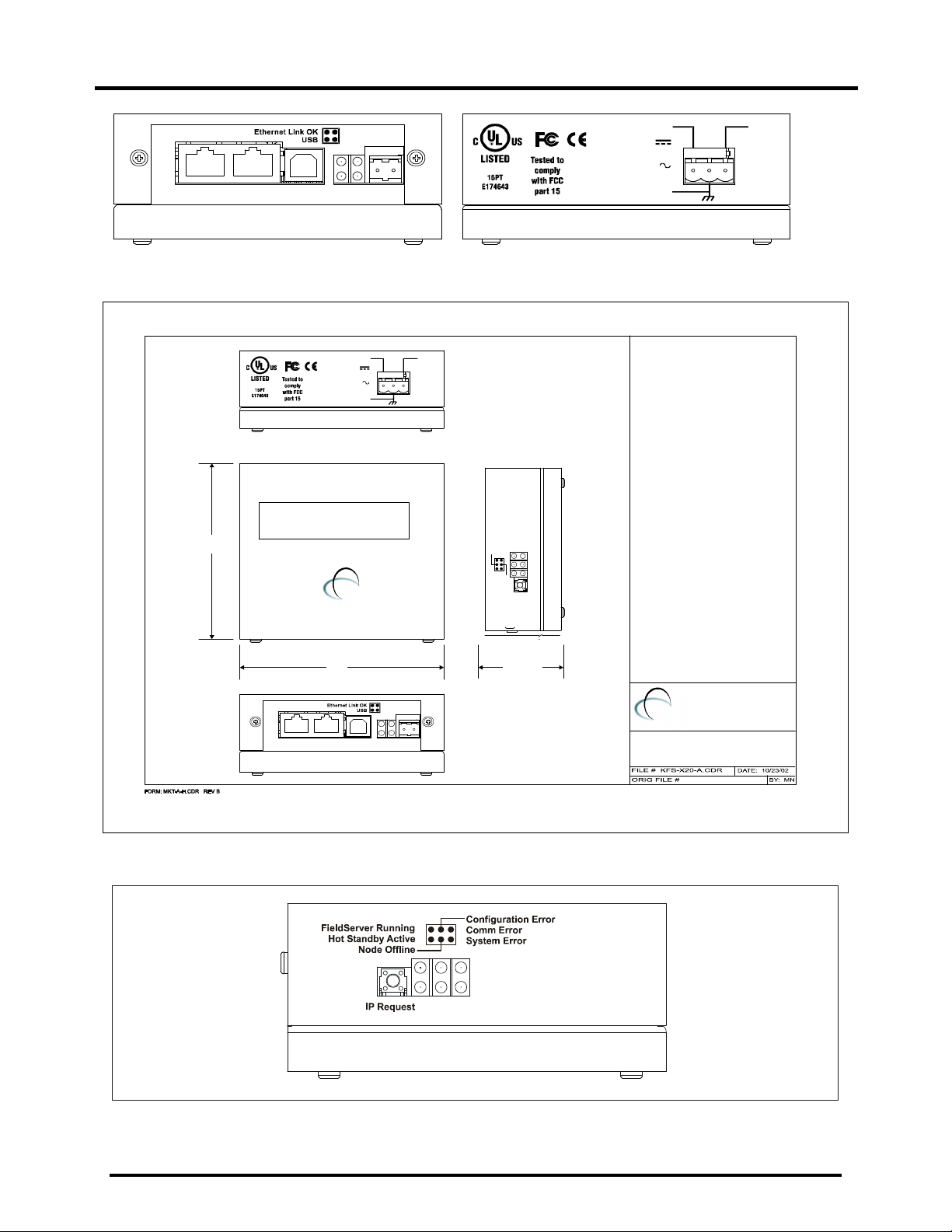
Figure 2-1: Diagram of FS-X20 showing Connection Ports
3.82"
9-30Vdc,1 A
24Vac, 5 0/60HZ, 1 A
Class 2 ( LPS)
Frame G round
FieldS erver
FIELD SERVE R BRID GE
FS-B2 010-01
INPUT:
OR
0V
Configuration Error
System Error
Comm Error
Node Offline
IP Request
Hot Standby Active
FieldServer Running
1.70"
FieldServer
Tech n olo g ies
(408) 262- 2299
FS-X 20
OUT LINE DI MEN SIONS
4.08"
Serial
RxTx RxTx
EthernetEIA232 USB E IA485
FieldServer
Tech n olo g ies
(408) 2 62-2299
www.fie ldserver.c om
Power OK
FieldBus A ctive
-
+
Figure 2-2: Diagram of FS-X20 Showing External Dimensions
Figure 2-3: Diagram of FS-X20 Showing LED’s
Page 4 FS-X20 Series FieldServer Start-up Guide (07-2005)
Page 6

Start-up guide
RX
YELLOW
RX
YELLOW
RX
YELLOW
RX
YELLOW
2.4. Supplied Connector Kit (FS-8915-11)
In order to facilitate RS-232 communications on the RJ-45 RS-232 port, a connector kit is supplied
containing one of each of the connectors shown in the diagram below. The tables in the diagram
show the functions applied to each of the RJ-45 pins by the FieldServer to assist in determination of
the required pinout configuration for connection to the third party device.
DB9 M
DB9F
X20
FUNCTION
CTS
DSR
GND
GND
DTR
RTS
TX
FS-8917-03
8
1
RJ4 5
WIRE LIST
FROM DEFAULT COLOR
RJ45-01
RJ45-02
RJ45-03
RJ45-04
RJ45-05
RJ45-06
RJ45-07
RJ45-08
DB9M - 02
DB9M - 08
DB9M - 06
DB9M - 05
DB9M - 04
DB9M - 07
DB9M - 03
GREY
BROWN
GREEN
RED
BLACK
ORANGE
BLUE
DB2 5M
FS-8 917 -01
FS-8917 -02
8
1
RJ45
WIRE LIST
X20
FUNCTION
CTS
DSR
GND
GND
DTR
RTS
TX
FROM
RJ45-01
RJ45-02
RJ45-03
RJ45-04
RJ45-05
RJ45-06
RJ45-07
RJ45-08
DEFAULT COLOR
DB9F - 03
DB9F - 05
DB9F - 02
WHITE
BROWN
GREEN
RED
BLACK
ORANGE
BLUE
DB25F
FS-8917 -04
8
1
WIRE LIST
FROM
RJ45-01
RJ45-02
RJ45-03
RJ45-04
RJ45-05
RJ45-06
RJ45-07
RJ45-08
DEFAULT
DB25F - 02
DB25F - 04
DB25F - 07
DB25F - 05
DB25F - 03
RJ45
COLOR
WHITE
BROWN
GREEN
RED
BLACK
ORANGE
BLUE
X20
FUNCTION
CTS
DSR
GND
GND
DTR
RTS
TX
8
1
WIRE LIST
FROM
RJ45-01
RJ45-02
RJ45-03
RJ45-04
RJ45-05
RJ45-06
RJ45-07
RJ45-08
RJ4 5
DEFAULT COLOR
DB25M - 03
DB25M - 05
DB25M - 07
DB25M - 04
DB25M - 02
WHITE
BROWN
GREEN
RED
BLACK
ORANGE
BLUE
X20
FUNCTION
CTS
DSR
GND
GND
DTR
RTS
TX
Figure 2-4: FieldServer Connector Reference
Page 5 FS-X20 Series FieldServer Start-up Guide (07-2005)
Page 7
Start-up guide
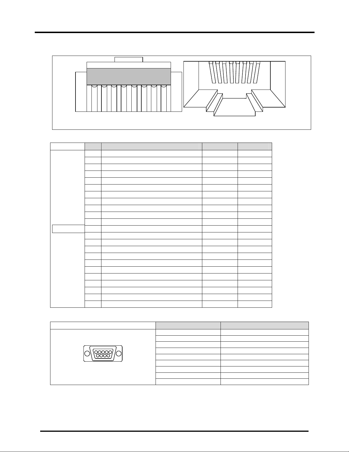
Note: FS-X20 Series RS-232 numbering convention is reverse to the 10BaseT numbering
convention.
12345678
12345678
RJ45 M a le M odula r Jack
RJ45 F emale M o dular J ack
Figure 2-5 RS-232/Cat 5 Wire Functions/Connections
PIN DESCRIPTION From DCE To DCE
1 Frame Ground
2 Transmitted Data D (Data)
3 Received Data D
4 Request to Send C (Control)
5 Clear to Send C
6 Data Set Ready C
7 Signal Gnd/Common return
8 Rcvd Line Signal Detector C
11 Undefined
12 Secondary Rcvd Line Signal Detector C
13 Secondary Clear to Send’ C
DB25 Male
14 Secondary Transmitted Data D
15 Transmitter Sig Element Timing T (Timing)
16 Secondary Received Data D
17 Receiver Sig Element Timing T
18 Undefined
19 Secondary Request to Send C
20 Data Terminal Ready C
21 Sig. Quality Detector C
22 Ring Indicator C
23 Data Sig Rate Detector C
24 Transmitter Sig Element Timing T
25 Undefined
Figure 2-6: - General PC Connector pinouts – DB25M
DB9 Male
Figure 2-7: - General PC Connector Pinouts – DB9M
PIN SIGNAL
1 Data Carrier Detect
2 Received Data
3 Transmitted Data
4 Data Terminal Ready
5 Signal Ground
6 Data Set Ready
7 Request to Send
8 Clear to Send
9 Ring Indicator
Page 6 FS-X20 Series FieldServer Start-up Guide (07-2005)
Page 8

Start-up guide
Serial
FS-X20
RJ45 Male Modular
Jack
ORANGE/WHITE
(RJ45-08)
BROWN
(RJ45-01)
+
FS-8917-16
-
G
BLUE/WHITE
(RJ45-04)
Figure 2-8: - RS-485 Connection pinouts on the serial RJ45 port.
Page 7 FS-X20 Series FieldServer Start-up Guide (07-2005)
Page 9

Start-up guide
3. Operation
3.1. Install and Run the Utility
Software
The FieldServer is shipped with a utility CDROM containing all the utility software that
needs to be installed.
All configuration file transfers and system
diagnostics are executed via the RUI or
“Remote User Interface” which is installed
with the utility software.
Insert the supplied Utility CD into the PC and
follow the installation instructions on the
screen.
Once installed, the FieldServer Utilities can
be located in the Windows Start menu.
Refer to the FieldServer Utilities manual for
information on how to connect to the
FieldServer via serial or Ethernet ports.
3.2. Use PING to Identify the
FieldServer on the Network
• Select Start|Programs|FieldServer
Utilities, browse to the Ping Utility and
select it
• The display should show
FieldServer Name
IP Number (192.168.2.X)
FieldServer Version
• If it does not (even after repeated
attempts) then either the network
cabling is incorrect or the computer
network card is faulty or incorrectly
configured.
• Check the Ethernet Link OK LED
displayed on the FieldServer. This LED
will be lit if the 10/100BaseT cable is
good. (Refer to Appendix B)
• Check the “Activity” LED on the Ethernet
connection (see Figure 2-3), this should
flash at least once every 2 seconds if
RUI is still running, and perhaps more
often, depending on network traffic.
(Refer to Appendix B)
• Check that the IP netmask of the PC
matches the FieldServer. This means
the first three sections of both IP
addresses match.
• Confirm that there is an Ethernet
adapter installed in the PC’s Device
Manager List, and that it is configured to
run the TCP/IP protocol.
• If using Windows XP, ensure that the
firewall is disabled.
3.3. Connect using “Remote User
Interface” (RUINET)
Browse to the Remote User Interface icon in
the Start menu directory and click on it - the
RUI menu screen should appear.
Refer to the FieldServer Utilities manual for
further information.
3.4. Use RUINET to change the
FieldServer IP Address and
Network
Should it be necessary to change the IP
address of the FieldServer, this can be done
via the “I” screen on Ruinet. Refer to the
FieldServer Utilities manual for details.
3.5. Upload the Default
Configuration
NOTE: Refer to the Configuration Manual
and the Driver Manual(s) provided with the
FieldServer for further information on
configuration files.
The configuration of the FieldServer is
provided to the FieldServer’s operating
system via a comma-delimited file called
“CONFIG.CSV”. If ordered with the
FieldServer, the custom configuration is
installed; (Reference documentation FS8790-XX). If a custom configuration is not
purchased, a template config.csv is loaded
on the FieldServer to facilitate user
configuration of the FieldServer.
The initial default configuration software will
be loaded on the FieldServer. In the main
menu of the Remote User Interface screen,
type “U” to upload the configuration. Then
type “U” again. The Utility will fetch the
default configuration and put it into the
Config File folder which is located in
(Start|Programs|FieldServerUtilities|Configur
ation File folder).
Page 8 FS-X20 Series FieldServer Start-up Guide (07-2005)
Page 10

Start-up guide
3.6. Change the Configuration File
to Meet the Application
Refer to the Configuration Manual in
conjunction with the Driver supplements for
information on configuring the FieldServer.
Note: FieldServer Technologies offers
training on this topic as well as a
configuration service to complete this portion
of the work. See www.fieldserver.com for
specific details.
The simulation utility mb8sim.exe can be
used to test configuration files. This file can
be found with the latest Utility CD (v.14 and
higher) or downloaded from the web.
Instructions on its use can be found in the
FieldServer Configuration Manual."
3.7. Download the Updated
Configuration File
Before attempting to send files to the
FieldServer, ensure that the files are in the
configuration file folder. Refer to the
FieldServer Utilities manual for further
information.
• From the main menu, type "D".
• Type "L" to specify the name and
extension of the file to be sent to the
FieldServer. Hit <Enter> when done.
• The Utility will automatically select
config.csv for download of csv files. On
rare occasions where other files need to
be downloaded to the FieldServer type
“O” for other files, then type “R” to
specify the remote filename needed on
the FieldServer.
• When satisfied that the correct file
names are specified, Type "D" to send
the file to the FieldServer. The utility will
display a menu showing download
progress.
• Note: Wait until the utility indicates
that download is complete before
resetting the FieldServer or you
could corrupt the FieldServer.
• Once download is complete, type <Esc>
to get back to the main menu and use
the "!" option (or simply cycle power to
the FieldServer) to put the new file into
operation.
Note that it is possible to do multiple
downloads to the FieldServer before
resetting it.
• (Firmware created by FieldServer
Technologies can be downloaded from
the configuration file by simply typing “F”
from the download menu.)
Note that FieldServer usually supplies
firmware upgrades as an install.zip, for
which a separate procedure is used, see
FieldServer utilities Manual for more
information.
3.8. Test and commission the
FieldServer
• Connect the FieldServer to the third
party device(s), and test the application.
• Should you experience problems, refer
to the Troubleshooting manual which
can be found in the FieldServer utilities
directory under Documentation.
• Before contacting FieldServer technical
support, create a log by using Serial and
Capture Utility (Ruidebug) to take a
snapshot or a serial capture log – see
FieldServer Utilities Manual for more
information. Send this log together with
the configuration file to
support@fieldserver.com for evaluation.
Note that application notes and other
resources are available on the web at
www.fieldserver.com.
Page 9 FS-X20 Series FieldServer Start-up Guide (07-2005)
Page 11

Start-up guide
Appendix A. Limited Warranty
FieldServer Technologies warrants its products to be free from defects in workmanship or material under
normal use and service for two years after date of shipment. FieldServer Technologies will repair or
replace without charge any equipment found to be defective during the warranty period. Final
determination of the nature and responsibility for defective or damaged equipment will be made by
FieldServer Technologies personnel.
All warranties hereunder are contingent upon proper use in the application for which the product was
intended and do not cover products which have been modified or repaired without FieldServer
Technologies approval or which have been subjected to accident, improper maintenance, installation or
application, or on which original identification marks have been removed or altered. This Limited
Warranty also will not apply to interconnecting cables or wires, consumables or to any damage resulting
from battery leakage.
In all cases FieldServer Technology’s responsibility and liability under this warranty shall be limited to the
cost of the equipment. The purchaser must obtain shipping instructions for the prepaid return of any item
under this warranty provision and compliance with such instruction shall be a condition of this warranty.
Except for the express warranty stated above, FieldServer Technologies disclaims all warranties with
regard to the products sold hereunder including all implied warranties of merchantability and fitness and
the express warranties stated herein are in lieu of all obligations or liabilities on the part of FieldServer
Technologies for damages including, but not limited to, consequential damages arising out of/or in
connection with the use or performance of the product.
Page 10 FS-X20 Series FieldServer Start-up Guide (07-2005)
Page 12

Start-up guide
The light should flash green once per second once the FieldServer has booted up.
Appendix B. LED Functions
Seria l
RxTx RxTx
Ethe rnetEIA2 32 USB E IA48 5
Light Description
This light relates to the Ethernet network port provided on the FieldServer. The
Ethernet Link OK light shows steady green when the physical connection to the
network hub is healthy. The Rx (Receive) light flashes green when the FieldServer
Ethernet Link
OK.
Power OK
Fieldbus
Active
FieldServer
Running
Configuration
Error
Comm Error
Hot Standby
Active
Node Offline
System Error
EIA-232
is receiving data from the network. The frequency of flashing is directly related to the
network activity. It does not necessarily mean data is being received by the
FieldServer. The Tx (Transmit) light flashes yellow when the FieldServer is sending
data. The frequency of flashing is directly proportional to the frequency of data
transmission.
This is the power light and should show steady green at all times when the
FieldServer is powered.
This light should show steady green when the Fieldbus connection is active.
Note that it may take a while from power up to booting up the FieldServer if the
loaded configuration is particularly large. The light indicates that the FieldServer
firmware is running.
A steady amber light will indicate a configuration error exists in the active
configuration. See the Error Screen in the Remote User Interface for a description of
the configuration error.
A steady red light will indicate the communications problem if there is a configured
node connected to the FieldServer that is offline. To establish the cause of the error,
go to the error screen of the RUI interface.
Not applicable
An amber light will flash when a configured node on the FieldServer is detected as
being offline. The flash will repeat after every unsuccessful retry.
A steady red light will indicate there is a system error on the FieldServer. If this
occurs, immediately report the related “system error” shown in the error screen of the
RUI interface to FieldServer Technologies for evaluation.
These lights, built into the connector, are related to the RS-232 serial port provided
on the FieldServer. The Rx (Receive) light flashes green when the FieldServer is
receiving data and the Tx (Transmit) light flashes yellow when the FieldServer is
sending data. The frequency of flashing is directly proportional to the frequency of
data transfer.
Pow er OK
Field Bus Acti ve
-
Field Serv er Ru nning
Hot S tandby Ac tive
Node Offline
+
IP R eques t
Conf igurat ion Error
Com m Err or
Syste m Error
Page 11 FS-X20 Series FieldServer Start-up Guide (07-2005)
Page 13

Start-up guide
THIS PAGE INTENTIONALLY LEFT BLANK.
Page 12 FS-X20 Series FieldServer Start-up Guide (07-2005)
 Loading...