

Page 1

Driver Version:
1.07
A Sierra Monitor Company
Driver Manual
(Supplement to the FieldServer Instruction Manual)
FS-8704-49 Data Aire (DAP)
APPLICABILITY & EFFECTIVITY
Effective for all systems manufactured after May 1, 2001
Document Revision: 9
Page 2

FS-8700-49_Data_Aire_DAP Table of Contents
TABLE OF CONTENTS
1.
Data Aire Description..................................................................................................... 4
1.1.
Performance Issues - DARTIII only............................................................................ 4
1.2.
Data Alarm Network Module Network LED Operation ................................................ 4
2.
Driver Scope of Supply .................................................................................................. 5
2.1.
Supplied by FieldServer Technologies for this driver.................................................. 5
3.
Hardware Connections .................................................................................................. 6
4.
Configuring the FieldServer as a Data Aire Client ....................................................... 7
4.1.
Data Arrays/Descriptors............................................................................................. 7
4.2.
Client Side Connection Descriptions .......................................................................... 8
4.3.
Client Side Node Descriptors ..................................................................................... 9
4.4.
Client Side Map Descriptors....................................................................................... 9
4.4.1. FieldServer Related Map Descriptor Parameters.................................................... 9
4.4.2. Driver Related Map Descriptor Parameters............................................................10
4.4.3. Timing Parameters ................................................................................................10
4.4.4. Map Descriptor Example 1 - Everything.................................................................11
4.4.5. Map Descriptor: Example 2 – Writing a Set-Point. .................................................11
4.4.6. Map Descriptor: Example 3 – Writing multiple points using one message..............12
Appendix A. Data Tables ....................................................................................................13
Appendix A.1. Data Table 1: Array Locations of ‘Everything’...............................................13
Appendix A.2. Data Table 2 - Point Descriptions.................................................................18
Appendix A.3. Data Table 3 - Unit Types ............................................................................25
Appendix B. Advanced Topics...........................................................................................26
Appendix B.1. Additional Driver Specific Map Descriptor Parameters .................................26
Appendix B.2. DA_Func Parameter - Permitted values.......................................................27
Appendix B.3. DA_Field Parameter - Permitted values. ......................................................28
Appendix B.4. DA_Method Parameter Values and Notes....................................................28
Appendix B.5. Advanced Map Descriptor 1:Collecting Data From Multiple Fileds ...............29
Appendix B.6. Advanced Map Descriptor Example 2:Collecting Error Messages................30
Appendix B.7. Advanced Map Descriptor Example 3: Using Special DA Field ....................30
Appendix B.8. Advanced Map Descriptor Example 4: - Using DA_Assoc............................31
Appendix B.9. Advanced Map Descriptor: Example 5 - Using a special / diagnostic
command.: 31
Appendix B.10. Advanced Map Descriptor: Example 6 – Turning Dap’s On/Off..................32
Appendix C. Troubleshooting Tips....................................................................................33
Appendix C.1. Bad Values ..................................................................................................33
Appendix C.2. Dead Nodes.................................................................................................33
Appendix C.3. Noise ...........................................................................................................33
Appendix C.4. Ignored Messages .......................................................................................33
Appendix C.5. Driver limitation............................................................................................33
Appendix C.6. Baud Rate....................................................................................................33
Appendix C.7. Wiring. .........................................................................................................33
Appendix C.8. Stuck Unit. ...................................................................................................34
Appendix C.9. Number of Units...........................................................................................34
Appendix D. Error Messages .............................................................................................35
Appendix D.1. Exposing Driver Statistics ............................................................................38
FieldServer Technologies 1991 Tarob Court Milpitas, California 95035 USA Web:www.FieldServer.com
Tel: (408) 262-2299 Fax: (408) 262-2269 Toll_Free: 888-509-1970 email: support@FieldServer.com
Page 3

FS-8700-49_Data_Aire_DAP Table of Contents
Appendix E. Writing data to DAP Devices ........................................................................40
Appendix E.1. Background..................................................................................................40
Appendix E.2. Associated Map Descriptors.........................................................................40
Appendix E.3. Starting/Stopping DAP devices ....................................................................41
Appendix E.4. DAP Unit Errors ...........................................................................................41
Appendix E.5. Using DA_Assoc correctly with Writes/Toggling Values ...............................46
Appendix F. Write Through’s.............................................................................................47
FieldServer Technologies 1991 Tarob Court Milpitas, California 95035 USA Web:www.FieldServer.com
Tel: (408) 262-2299 Fax: (408) 262-2269 Toll_Free: 888-509-1970 email: support@FieldServer.com
Page 4

FS-8700-49_Data_Aire_DAP Page 4 of 48
1. Data Aire Description
The Data Aire Driver is capable of direct connection to a network of Data Aire DAP devices.
The FieldServer is connected in a RS-485 loop topology. Two FieldServer ports are required
per loop. The driver is an active client. All data is obtained by poll & response.
Connection to a DART is not supported by this driver.
The driver may be configured very simply (See Section 4.4). A number of advanced
configurations are also available and are described in Appendix B. The driver supports the
common message formats for common Data Aire DAP devices. A list of the supported
messages is provided in the manual.
The information that follows describes how to expand upon the factory defaults provided in the
configuration files included with the FieldServer.
1.1. Performance Issues - DARTIII only
Data Aire communication is based on a very low baud rate. In addition inter-message timing
constraints and overhead requirements for active messages in a Dart configuration add
significant time to each transaction. It is not possible to write a setpoint to a device until the
device has been successfully read, and the result of the write will not be seen until the next
read is complete. The result of a write may not be seen for some time due to slow
communications and significant inter poll delays.
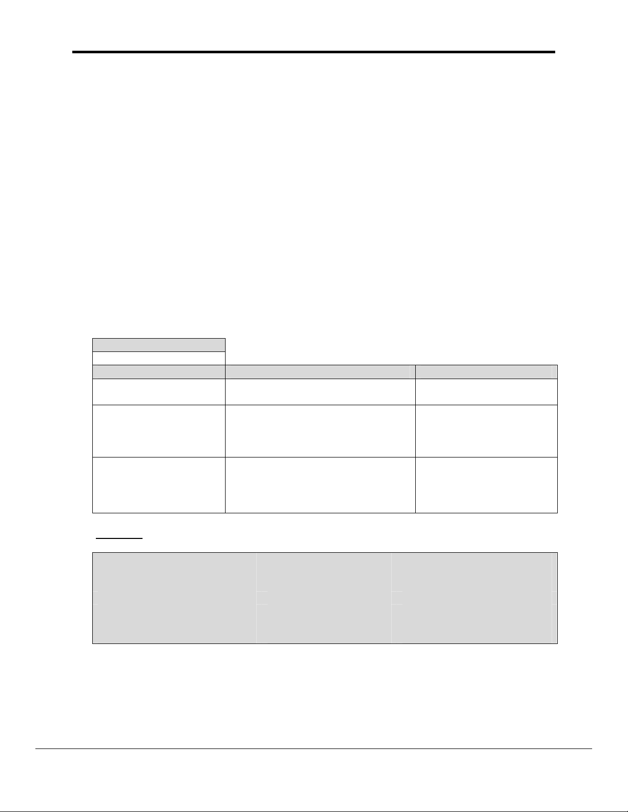
1.2. Data Alarm Network Module Network LED Operation
DAP-II units communicate with a DART unit by using a Data Alarm Network Module. This
module provides a RS-485 communications link. Installed on the card are several LEDS.
The table below explains how the LEDS appear under normal (correctly functioning)
operation.
LED LED Appearance
The Network Module has a blown fuse detection circuit. If one (or more) of
FUSE
DS1 &
DS3
NETWORK
the fuses has an open circuit, then the FUSE LED will be lit. Normally, this
LED is dark.
Communications signals enter and leave the Network Module. These LEDS
reflect the communications activity. When first powered up, both LED's will
be lit and the illumination will be steady. As the DART communicates with
the network, both LED’s will begin to flicker in unison. All of the Network
Module LED’s will flicker at the same time.
At some point the DART will send a communication message to a specific
network-connected DAP-II that requires a reply to the DART. If the message
is received without error, the DAP-II will reply by engaging a relay on the
Network Module and transmitting a message. When this happens the
NETWORK LED will come on. Whenever a NETWORK LED is seen to
come on it means that the communications into the Network Module is
satisfactory. It is still possible to have a wiring problem downstream of the
module that prevents the message from being received by the DART
FieldServer Technologies 1991 Tarob Court Milpitas, California 95035 USA Web:www.FieldServer.com
Tel: (408) 262-2299 Fax: (408) 262-2269 Toll_Free: 888-509-1970 email: support@FieldServer.com
Page 5

FS-8700-49_Data_Aire_DAP Page 5 of 48
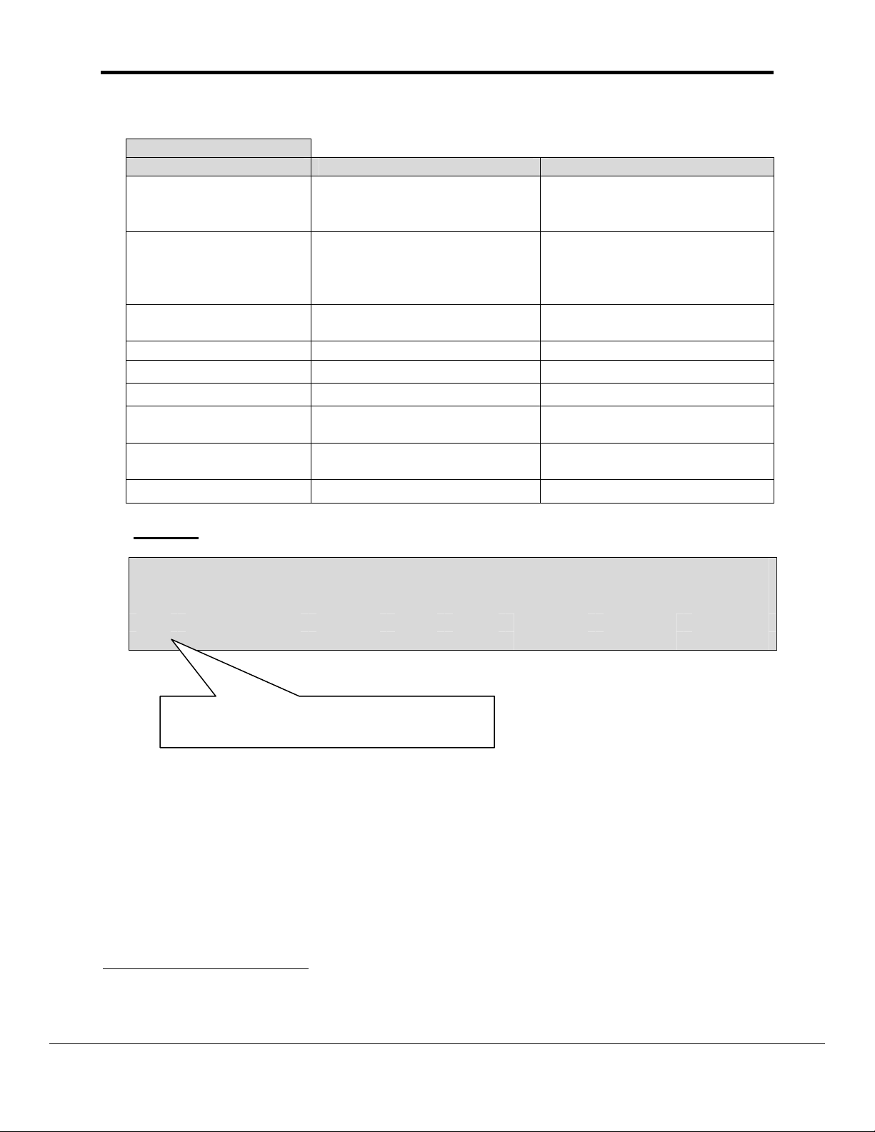
2. Driver Scope of Supply
2.1. Supplied by FieldServer Technologies for this driver
FieldServer Technologies
PART #
Description
RS-485 connection adapter
FS-8700-49 Driver Manual.
FieldServer Technologies 1991 Tarob Court Milpitas, California 95035 USA Web:www.FieldServer.com
Tel: (408) 262-2299 Fax: (408) 262-2269 Toll_Free: 888-509-1970 email: support@FieldServer.com
Page 6
FS-8700-49_Data_Aire_DAP Page 6 of 48
P1
A
A
A
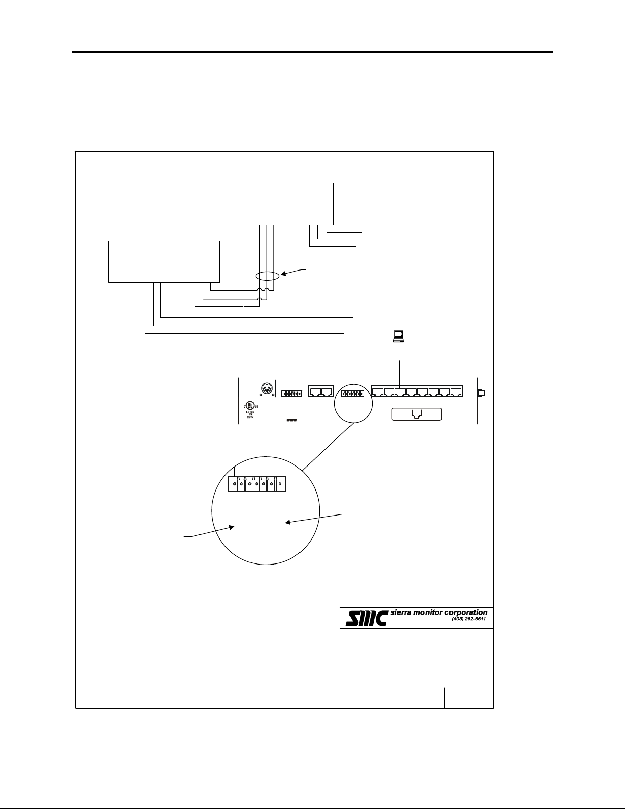
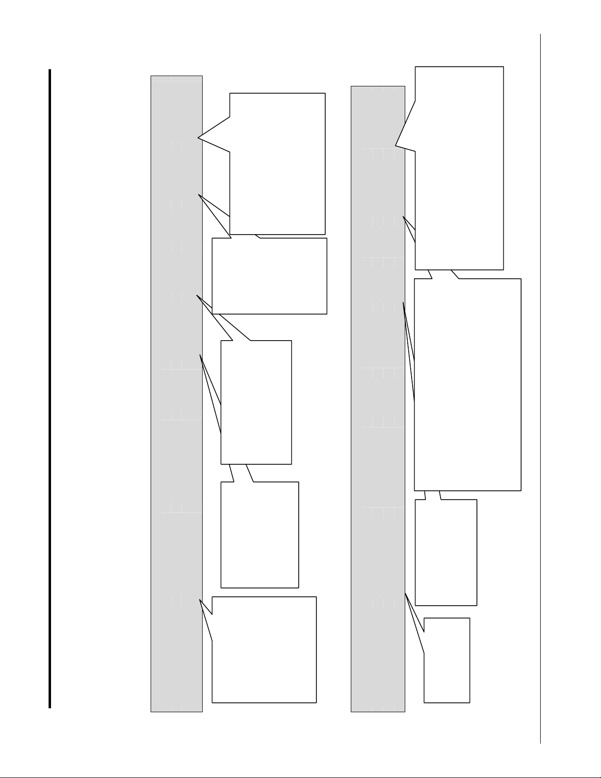
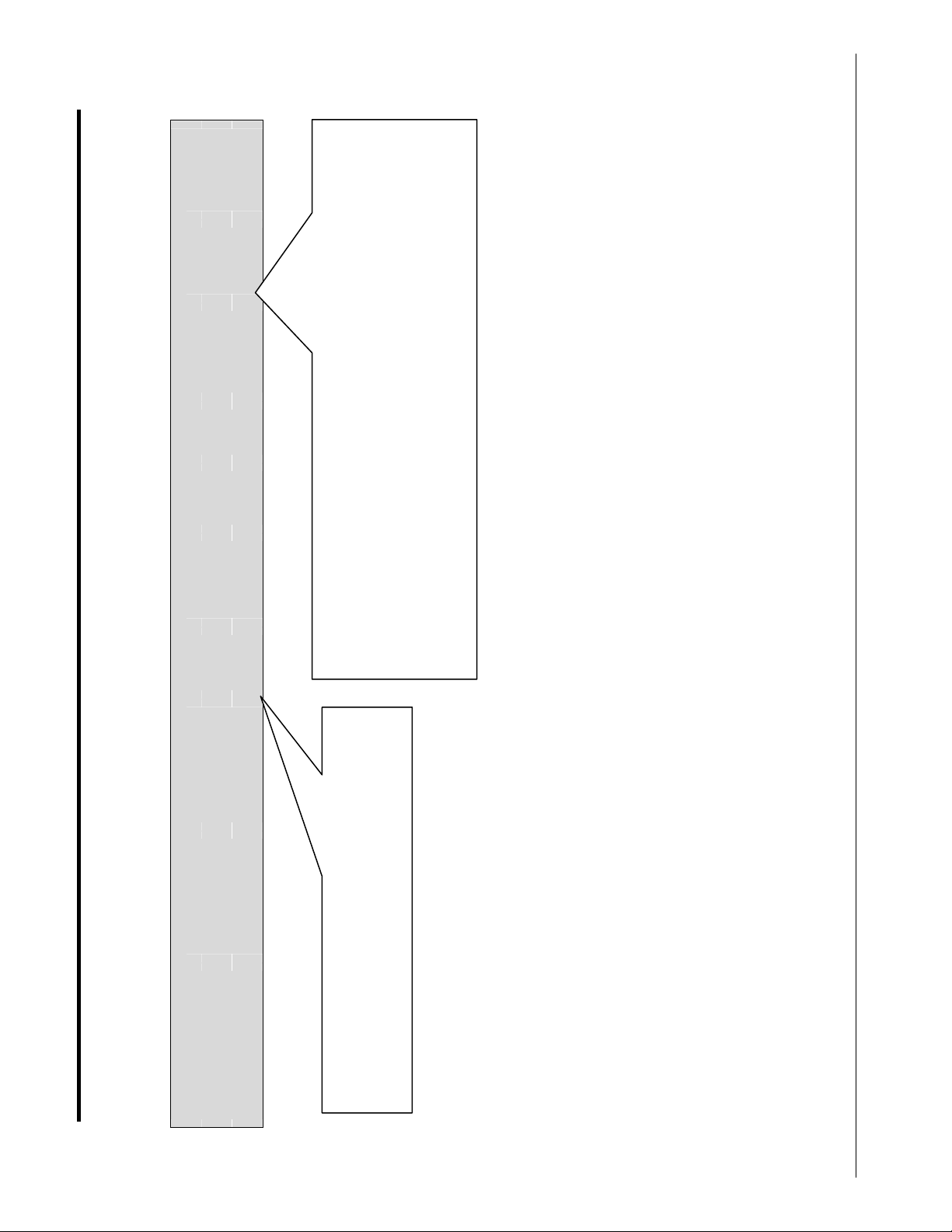
3. Hardware Connections
The FieldServer is connected to the DAP devices as shown in connection drawing.
Configure the DAP devices according to manufacturer’s instructions
Dap/Chiller/Dap80
+OUT
-OUT
SHD
Dap/Chiller/Dap80
+IN
-IN
SHD
+OUT
-OUT
SHD
FOR THIS WIRING
ARRANGEMENT THIS
IS THE PRIMARY PORT
+IN
-IN
SHD
TO OTHER DEVICES
RS485
9600 N81
CONFIG PC
(RUISYS)
MODEL 8051
_
_
SYSTEM NODE: 8
GndFG_
+
Power
0V
DC AUX Power
Gnd_+
+
+12V 500m
12V 500m
5V 1.5A
Net 1
Net 2
5V 500 m
FG
Ethernet
10 Base T
Gnd_+
GndFG_
+
R2 R1
RS 485
(Opto - Isolated)
SECONDARY PORT
P8 P7 P6 P5 P4 P3 P2
GROUND 5
DTR 6
RTS 7
Tx 8
RS 232
1 Rx
18
2 CTS
3 DSR
4 GRO UND
R2 R1
RS 485
(Opto - Isolated)
MODEL 8051
MANUAL - DataAire
BASE NAME:
FILE NAME: T28700-49.VSD
DATE: 1/22/01
BY: MN
FieldServer Technologies 1991 Tarob Court Milpitas, California 95035 USA Web:www.FieldServer.com
Tel: (408) 262-2299 Fax: (408) 262-2269 Toll_Free: 888-509-1970 email: support@FieldServer.com
Page 7
FS-8700-49_Data_Aire_DAP Page 7 of 48
4. Configuring the FieldServer as a Data Aire Client
For a detailed discussion on FieldServer configuration, please refer to the FieldServer
instruction manual. The information that follows describes how to expand upon the factory
defaults provided in the configuration files included with the FieldServer (See “.csv” sample files
provided with the FieldServer).
This section documents and describes the parameters necessary for configuring the FieldServer
to communicate with a Data Aire Server
4.1. Data Arrays/Descriptors
The configuration file tells the FieldServer about its interfaces, and the routing of data
required. In order to enable the FieldServer for Data Aire communications, the driver
independent FieldServer buffers need to be declared in the “Data Arrays” section, the
destination device addresses need to be declared in the “Client Side Nodes” section, and
the data required from the servers needs to be mapped in the “Client Side Map Descriptors”
section. Details on how to do this can be found below.
Note that in the tables, * indicates an optional parameter, with the bold legal value being the
default.
Section Title
Data_Arrays
Column Title Function Legal Values
Data_Array_Name Provide name for Data Array
Up to 15 alphanumeric
characters
Float, Bit, UInt16, SInt16,
Data_Array_Format
Provide data format. Each Data
Array can only take on one format.
Packed_Bit, Byte,
Packed_Byte,
Swapped_Byte
Number of Data Objects. Must be
Data_Array_Length
larger than the data storage area
required by the Map Descriptors for
1-10,000
the data being placed in this array.
Example
// Data Arrays
Data_Arrays
Data_Array_Name, Data_Format, Data_Array_Length,
DA_AI_01, UInt16, 200
DA_AO_01, UInt16, 200
DA_DI_01, Bit, 200
DA_DO_01, Bit, 200
FieldServer Technologies 1991 Tarob Court Milpitas, California 95035 USA Web:www.FieldServer.com
Tel: (408) 262-2299 Fax: (408) 262-2269 Toll_Free: 888-509-1970 email: support@FieldServer.com
Page 8
FS-8700-49_Data_Aire_DAP Page 8 of 48
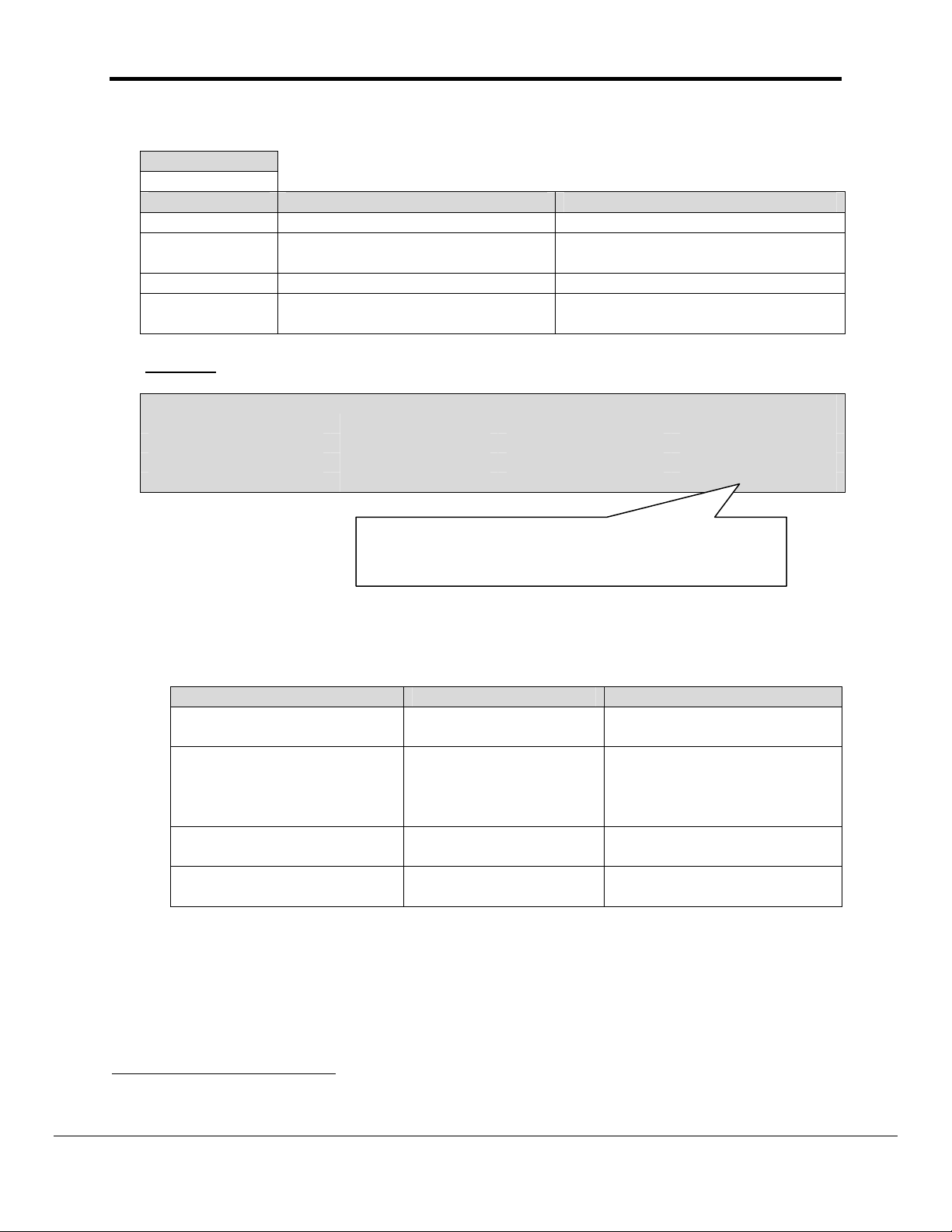
4.2. Client Side Connection Descriptions
Connections
Column Title Function Legal Values
This is the FieldServer port
Port
connected to the DART’s RS232 port.
The return loop from the DAP
Secondary_Port*
devices is connected to this
port. (Loop connected to Tx+
& Tx- terminals.
Baud* Specify baud rate
Parity* Specify parity
Data_Bits*
Stop_Bits*
Protocol
Handshaking*
Poll Delay*
Specify data bits
Specify stop bits
Specify protocol used. Either
keyword may be used.
Specify hardware
handshaking
Time between internal polls
Example
// Client Side Connections
Connections
Port, Secondary Port, Protocol, Baud, Parity, Data_Bits, Stop_Bits, Poll_Delay
R1, R2, DAP, 2400, None, 8, 1, 0.100s
P1-P8, R1-R21
(P1-P8) requires 232/485
converter.
P1-P8, R1-R21
(R1-R2) requires 232/485
converter.
2400/96002 (Vendor
Limitation)
None
8
1
DAP, Daire
None
0-32000s, 1s
Use this port identifier in the client side node
configuration described in Section 4.3.
1
Not all ports shown are necessarily supported by the hardware. Consult the appropriate Instruction
manual for details of the ports available on specific hardware.
2
DAP V9.5 or later supports 9600
FieldServer Technologies 1991 Tarob Court Milpitas, California 95035 USA Web:www.FieldServer.com
Tel: (408) 262-2299 Fax: (408) 262-2269 Toll_Free: 888-509-1970 email: support@FieldServer.com
Page 9
FS-8700-49_Data_Aire_DAP Page 9 of 48
4.3. Client Side Node Descriptors
Section Title
Nodes
Column Title Function Legal Values
Node_Name Provide name for node Up to 32 alphanumeric characters
Node_ID
Protocol Specify protocol used DAP
Connection
Example
// Client Side Nodes
Nodes
Node_Name Node_ID Protocol Connection
Unit1, 1, DAP, R1
Modbus station address of
physical server node
Specify which port the device is
connected to the FieldServer
1-259
P1-P8, R1-R23
This is the connection to the primary port identified with the
'Port' keyword in the connection configuration described in
Section 4.2
4.4. Client Side Map Descriptors
4.4.1. FieldServer Related Map Descriptor Parameters
Column Title Function Legal Values
Map_Descriptor_Name
Data_Array_Name
Data_Array_Offset
Function
Name of this Map
Descriptor
Name of Data Array
where data is to be
stored in the
FieldServer
Starting location in Data
Array
Function of Client Map
Descriptor
Up to 32 alphanumeric
characters
One of the Data Array
names from “Data Array”
section above
0 to maximum specified in
“Data Array” section above
RDBC, WRBC, WRBX
3
Not all ports shown are necessarily supported by the hardware. Consult the appropriate Instruction
manual for details of the ports available on specific hardware.
FieldServer Technologies 1991 Tarob Court Milpitas, California 95035 USA Web:www.FieldServer.com
Tel: (408) 262-2299 Fax: (408) 262-2269 Toll_Free: 888-509-1970 email: support@FieldServer.com
Page 10

FS-8700-49_Data_Aire_DAP Page 10 of 48
4.4.2. Driver Related Map Descriptor Parameters
Column Title Function Legal Values
Node_Name
Name of Node to fetch data
from
Data_Type Data type Register, Coil, AI, DI
Length Length of Map Descriptor 1
Address Starting address of read block
Only required when the function
is a Read (rdbc).
Tells the driver to poll the
DA_Func*
device for all the data that is
available. The data is device
specific.
Other uses of this parameter
are discussed in Appendix B .
Required when the function is a
write (wrbc) or when the Map
Descriptor is associated with a
write by means of the
DA_Field
DA_Assoc parameter value.
This is the name of the data
field whose value you wish to
set in the device.
Other uses of this parameter
are discussed in Appendix B.
Use to associate passive Map
Descriptors with an active Map
Descriptor. Multiple fields can
DA_Assoc
be associated with one WRBC
Map Descriptor, thus writing
multiple values to one device
using just one message.
One of the node names
specified in “Client Node
Descriptor” above
Not required for client
configuration - used in
simulation configuration only.
Everything – See Appendix A
See Appendix A.2 for a list of
permitted values.
Any positive integer. See
Appendix E
4.4.3. Timing Parameters
Column Title Function Legal Values
Scan_Interval Rate at which data is polled ≥0.1s
FieldServer Technologies 1991 Tarob Court Milpitas, California 95035 USA Web:www.FieldServer.com
Tel: (408) 262-2299 Fax: (408) 262-2269 Toll_Free: 888-509-1970 email: support@FieldServer.com
Page 11
The scan interval is used to
control the minimum time
between poll messages. It
may take several polls /
messages to obtain a
complete data set (the
number is dependent on the
This is how often the data will be written to
the device. Reduce the scan interval when
using a dart. The dart will only take control
of the devices when the network has been
idle for at least 50 seconds. If polls are
generated too often, the dart will never
exercise control.
Tells the
driver that
this Map
Descriptor is
used to (poll
&) store a
complete
data set from
the unit.
to zero and the length to
1300 as this is the max
number of data points
Always set the Address
that can be read
Select the data field from Appendix B.3.
Ensure that the keyword can be written to the
unit type identified as unit1. Example. If unit1 is a Chiller then the above
Map Descriptor will not function correctly as it
can only be used to write to unit types
7,9,14,15.
The node name
connects the Map
Descriptor to a node
definition which in
turn is connected to
a port.
Always leave the
4.4.4. Map Descriptor Example 1 - Everything
It is recommended
that the format of
the Data Array be
FLOAT as the data
read from the unit
consists of bits,
bytes and real
numbers.
The data that is obtained from ‘unit1’ is dependent on the type of device. Irrespective of the device type the arrangement of data,
stored in DA_01, is fixed. If a data field cannot be obtained from ‘unit1’ then the array is left with a zero value for that data field.
FS-8700-49_Data_Aire_DAP Page 11 of 48
The FieldServer listens passively for all possible data from the device called ‘unit1’ and stores the data in an array called ‘DA_01’.
// Client Side Map Descriptors
Map Descriptors
Map_Descriptor_Name, Data_Array_Name, Data_Array_Offset, Function, Node_Name, Address, Length, DA_Func, Scan_Interval
Read_Node_01, DA_01, 0, RDBC, Unit1, 0, 1300, Everything, 2.5s
4.4.5. Map Descriptor: Example 2 – Writing a Set-Point.
// Client Side Map Descriptors
Map Descriptors
Map_Descriptor_Name, Data_Array_Name, Data_Array_Offset, Function, Node_Name, Address Length, DA_Field, Scan_Interval
Write_SP_01, DA_SETPOINTS, 0, WRBC, Unit1, 0, 1, nom_h_setpt, 120s
.
address set to zero
and the length as
one
Tel: (408) 262-2299 Fax: (408) 262-2269 Toll_Free: 888-509-1970 email: support@FieldServer.com
FieldServer Technologies 1991 Tarob Court Milpitas, California 95035 USA Web:www.FieldServer.com
The setpoint is
obtained from
this Data Array.
Page 12
this way the driver will use only one message to write to the device. The
message will be built using both Map Descriptors. This method reduces the
Associate the passive Map Descriptor to the active (wrbc) Map Descriptor. In
communication load. The association is made using the DA_Assoc parameter. Use unique positive
integers. Omitting the DA_Assoc parameter when using ‘passive’ Map
Descriptors will produce ambiguous results.
Tel: (408) 262-2299 Fax: (408) 262-2269 Toll_Free: 888-509-1970 email: support@FieldServer.com
FieldServer Technologies 1991 Tarob Court Milpitas, California 95035 USA Web:www.FieldServer.com
4.4.6. Map Descriptor: Example 3 – Writing multiple points using one message.
will update two fields, the nom_h_setpt and the t_setpt.
The write Map Descriptor. must precede the passive.
A 'Write' and a passive to the same node. This write
FS-8700-49_Data_Aire_DAP Page 12 of 48
// Client Side Map Descriptors
Map Descriptors
Map_Descriptor_Name, Data_Array_Name, Data_Array_Offset, Function, Node_name, Address, Length, DA_Field, DA_Assoc, Scan_Interval
Write_Map Descriptor_1, DA_SETPOINTS, 0, WRBC, Unit1, 0, 1, nom_h_setpt, 2, 120s
Additional information is provided in Appendix B
Write_Map Descriptor_1, DA_SETPOINTS, 1, passive, Unit1, 0, 1, t_setpt, 2,
For a Dart, use wrbx instead of wrbc.
Page 13

FS-8700-49_Data_Aire_DAP Page 13 of 48
Appendix A. Data Tables
Appendix A.1. Data Table 1: Array Locations of ‘Everything’
In the following table the array location indicates the offset in the Data Array at which a data
field can be found. (This offset is relative to the offset specified in the Map Descriptor) The
columns headed 2, 3 … indicate the unit types for which the data fields are available. For
example: The field ‘d_temp’ can be read from unit types 2, 5,6,7,9 but not from any of the
other unit types. It is beyond the scope of this manual to describe each field and to indicate
valid ranges. Such information should be obtained from the Data Aire Corporation.
‘x’ Indicates Read only
‘X’ Indicates a point that can be read & written.
‘w’ Indicates a write only point.
Array
Location
1 1 1 Zone w w w w w w w w w
2 1 1 Inhibit w w w w w w w w w
3 4 1 unitType x x x x x x x x x x
4 2 1 temp x x x x x Dap-Stat
5 2 1 hum x x x x x Dap-Stat
6 2 1 d_temp x x x x x Dap-Stat
7 3 8 mode x x x x x Dap-Stat
23 3 8 hold x x x x x Dap-Stat
39 1 1 cs_on x x x x x Dap-Stat
40 1 1 hs_on x x x x x Dap-Stat
41 1 1 valvePCT x x x x x Dap-Stat
42 1 1 hVlvPCT x x x x x Dap-Stat
43 4 14
57 2 1 hiTemp x x x x x Dap-Stat
58 2 1 loTemp x x x x x Dap-Stat
59 2 1 hiHum x x x x x Dap-Stat
60 2 1 loHum x x x x x Dap-Stat
61 1 1 chilled_water x x x x x Dap-Stat
62 1 1 compressor_config x x x x x Dap-Stat
63 1 1 heat_strip_config x x x x x Dap-Stat
64 1 1 hum_config x x x x x Dap-Stat
65 1 1 csUtilPct x x x x x Dap-Stat
66 1 1 hsUtilPct x x x x x Dap-Stat
67 1 1 valveUtilPct x x x x x Dap-Stat
68 1 1 humUtilPCT x x x x x Dap-Stat
69 1 1 alrm_select_1 x x x x x Dap-Stat
70 1 1 alrm_select_2 x x x x x Dap-Stat
71 1 1 alrm_select_3 x x x x x Dap-Stat
72 1 1 alrm_select_4 x x x x x Dap-Stat
Method
Num
Elements
Data Field 2 3 4 5 6 7 8 9 14 15 Message Type
Errors - see Appendix E.4
for more information
x x x x x Dap-Stat
Dap-Config
Dap-Config
Dap-Unit
FieldServer Technologies 1991 Tarob Court Milpitas, California 95035 USA Web:www.FieldServer.com
Tel: (408) 262-2299 Fax: (408) 262-2269 Toll_Free: 888-509-1970 email: support@FieldServer.com
Page 14

FS-8700-49_Data_Aire_DAP Page 14 of 48
Array
Location
73 3 56
185 1 1 runtime_c1 x x x x x Dap-Xtra
186 1 1 runtime_c2 x x x x x Dap-Xtra
187 1 1 runtime_c3 x x x x x Dap-Xtra
188 1 1 runtime_c4 x x x x x Dap-Xtra
189 1 1 runtime_ht1 x x x x x Dap-Xtra
190 1 1 runtime_ht2 x x x x x Dap-Xtra
191 1 1 runtime_ht3 x x x x x Dap-Xtra
192 1 1 runtime_hum x x x x x Dap-Xtra
193 1 1 runtime_evap x x x x x Dap-Xtra
194 1 1 runtime_cond x x x x x Dap-Xtra
195 1 1 runtime_dehum x x x x x Dap-Xtra
196 1 1 runtime_esc x x x x x Dap-Xtra
197 1 1 runtime_cwc x x x x x Dap-Xtra
198 4 20 errors x x x x x Dap-Xtra
218 6 10 errage x x x x x Dap-Xtra
258 1 1 version x x x x x Dap-Xtra
259 2 1 tmbmair x x x x x Dap-Xtra
260 2 1 tmbhum x x x x x Dap-Xtra
261 1 1 tmbairdb x x x x x Dap-Xtra
262 6 13 runtimes (as array) x x x x x Dap-Xtra
314 3 80 bitErrors x x x x x Dap-Xtra
474 4 1 adj_rate X X X Dap-Menu
478 1 1 alrm_delay_1 X X X Dap-Menu
479 1 1 alrm_delay_2 X X X Dap-Menu
480 1 1 alrm_delay_3 X X X Dap-Menu
481 4 1 alrm_enable_1 X X X Dap-Menu
482 4 1 alrm_enable_2 X X X Dap-Menu
483 4 1 alrm_enable_3 X X X Dap-Menu
484 4 1 alrm_select_1 X X X Dap-Menu
485 4 1 alrm_select_2 X X X Dap-Menu
486 4 1 alrm_select_3 X X X Dap-Menu
487 1 1 chilled_water X X X Dap-Menu
488 1 1 compressor_config X X X Dap-Menu
489 1 1 c_mode X X X Dap-Menu
490 2 1 fire_lim X X X Dap-Menu
491 1 1 heat_strip_config X X X Dap-Menu
492 1 1 hi_cal X X X Dap-Menu
493 1 1 hi_h_cal X X X Dap-Menu
494 2 1 hi_t_lim X X X Dap-Menu
495 1 1 humid_config X X X Dap-Menu
496 1 1 h_calib X X X Dap-Menu
497 1 1 lead_lag X X X Dap-Menu
Method
Num
Elements
Data Field 2 3 4 5 6 7 8 9 14 15 Message Type
bitErrors - see Appendix
E.4 for more information
x x x x x Dap-Stat
FieldServer Technologies 1991 Tarob Court Milpitas, California 95035 USA Web:www.FieldServer.com
Tel: (408) 262-2299 Fax: (408) 262-2269 Toll_Free: 888-509-1970 email: support@FieldServer.com
Page 15

FS-8700-49_Data_Aire_DAP Page 15 of 48
Array
Location
498 1 1 loc_h_deadband X X X Dap-Menu
499 1 1 loc_h_setpt X X X Dap-Menu
500 2 1 loc_t_dband X X X Dap-Menu
501 2 1 loc_t_setpt X X X Dap-Menu
502 1 1 lo_cal X X X Dap-Menu
503 1 1 lo_h_lim X X X Dap-Menu
504 2 1 lo_t_lim X X X Dap-Menu
505 1 1 main_int X X X Dap-Menu
506 1 1 passwd_a X X X Dap-Menu
507 1 1 passwd_b X X X Dap-Menu
508 1 1 rst_mode X X X Dap-Menu
509 1 1 s_delay X X X Dap-Menu
510 2 1 t_calib X X X Dap-Menu
511 1 1 voice X X X Dap-Menu
512 1 1 vvrg X X X Dap-Menu
513 1 1 cat1 X X X Dap-Menu
514 1 1 cat2 X X X Dap-Menu
515 1 1 cat3 X X X Dap-Menu
516 2 1 d_calib X X X Dap-Menu
517 2 1 lo_d_lim X X X Dap-Menu
518 1 1 ptc X X X Dap-Menu
519 2 1 supplyT x x x Chiller-Stat
520 2 1 returnT x x x Chiller-Stat
521 4 1 coolOn1 x x x Chiller-Stat
522 4 2 coolOn2 x x x Chiller-Stat
523 4 2 coolOn3 x x x Chiller-Stat
524 2 1 valvePct x x x Chiller-Stat
525 4 1 pumpsOn x x x Chiller-Stat
526 4 1 condOn x x x Chiller-Stat
527 4 1 modFail x x x Chiller-Stat
528 2 1 hiSupT x x x Chiller-Stat
529 2 1 loSupT x x x Chiller-Stat
530 2 1 hiRetT x x x Chiller-Stat
531 2 1 loRetT x x x Chiller-Stat
532 1 1 csUtilPct1 x x x Chiller-Stat
533 1 1 csUtilPct2 x x x Chiller-Stat
534 1 1 csUtilPct3 x x x Chiller-Stat
535 1 1 valveUtilPct x x x Chiller-Stat
536 3 48
584 1 1 mode x x x Chiller-Stat
585 6 11 runtimes x x x Chiller-Xtra
596 3 80 errold x x x Chiller-Xtra
676 6 10 errage x x x Chiller-Xtra
Method
Num
Elements
Data Field 2 3 4 5 6 7 8 9 14 15 Message Type
Errors - see Appendix E.4
for more information
x x x Chiller-Stat
FieldServer Technologies 1991 Tarob Court Milpitas, California 95035 USA Web:www.FieldServer.com
Tel: (408) 262-2299 Fax: (408) 262-2269 Toll_Free: 888-509-1970 email: support@FieldServer.com
Page 16

FS-8700-49_Data_Aire_DAP Page 16 of 48
Array
Location
854 4 1 adjust_rate x x x Chiller-Menu
855 4 1 auto_ack X X X Chiller-Menu
856 2 1 aux_setpt X X X Chiller-Menu
857 4 1 backup_mods X X X Chiller-Menu
858 2 1 backup_setpt X X X Chiller-Menu
859 4 1 cmota X X X Chiller-Menu
860 4 1 comp_type X X X Chiller-Menu
861 4 1 ptc X X X Chiller-Menu
862 2 1 hi_r_lim X X X Chiller-Menu
863 2 1 hi_s_lim X X X Chiller-Menu
864 4 1 LL_policy X X X Chiller-Menu
865 2 1 lo_r_lim X X X Chiller-Menu
866 2 1 lo_s_lim X X X Chiller-Menu
867 1 1 main_int X X X Chiller-Menu
868 4 1 mods_configd X X X Chiller-Menu
869 1 1 network_ID X X X Chiller-Menu
870 1 1 op_1_delay X X X Chiller-Menu
871 1 1 op_2_delay X X X Chiller-Menu
872 4 1 op_1_message X X X Chiller-Menu
873 4 1 op_2_message X X X Chiller-Menu
874 1 1 password X X X Chiller-Menu
875 4 4 relay_mask_0 X X X Chiller-Menu
879 4 4 relay_mask_1 X X X Chiller-Menu
883 4 4 relay_mask_2 X X X Chiller-Menu
887 4 1 restart_mode X X X Chiller-Menu
888 4 1 reverse_valve X X X Chiller-Menu
889 4 1 sc_alarm_on X X X Chiller-Menu
890 1 1 start_delay X X X Chiller-Menu
891 1 1 supply_dband X X X Chiller-Menu
892 2 1 supply_setpt X X X Chiller-Menu
893 4 1 temp_scale X X X Chiller-Menu
894 4 1 valve_voltage X X X Chiller-Menu
895 4 1 voice X X X Chiller-Menu
896 4 1 water_valve X X X Chiller-Menu
897 1 1 return_cal X X X Chiller-Menu
898 1 1 supply_cal X X X Chiller-Menu
899 4 1 adj_rate X X X X Dap80-Menu
900 1 1 alrm_delay_1 X X X X Dap80-Menu
901 1 1 alrm_delay_2 X X X X Dap80-Menu
902 1 1 alrm_delay_3 X X X X Dap80-Menu
903 1 1 alrm_delay_4 X X X X Dap80-Menu
904 4 1 alrm_select_1 X X X X Dap80-Menu
905 4 1 alrm_select_2 X X X X Dap80-Menu
906 4 1 alrm_select_3 X X X X Dap80-Menu
Method
Num
Elements
Data Field 2 3 4 5 6 7 8 9 14 15 Message Type
FieldServer Technologies 1991 Tarob Court Milpitas, California 95035 USA Web:www.FieldServer.com
Tel: (408) 262-2299 Fax: (408) 262-2269 Toll_Free: 888-509-1970 email: support@FieldServer.com
Page 17

FS-8700-49_Data_Aire_DAP Page 17 of 48
Array
Location
907 4 1 alrm_select_4 X X X X Dap80-Menu
908 4 1 ant-enable X X X X Dap80-Menu
909 4 1 autoflush_time X X X X Dap80-Menu
910 4 1 auto_ack X X X X Dap80-Menu
911 4 1 comp_config X X X X Dap80-Menu
912 4 1 control_type X X X X Dap80-Menu
913 4 1 c_mode X X X X Dap80-Menu
914 4 1 da_volts X X X X Dap80-Menu
915 4 1 dehum_on X X X X Dap80-Menu
916 2 1 d_calib X X X X Dap80-Menu
917 4 1 esaver_supp_comp X X X X Dap80-Menu
918 2 1 fire_lim X X X X Dap80-Menu
919 4 1 heater_config X X X X Dap80-Menu
920 2 1 hi_h_lim X X X X Dap80-Menu
921 2 1 hi_t_lim X X X X Dap80-Menu
922 4 1 humid_config X X X X Dap80-Menu
923 2 1 h_calib X X X X Dap80-Menu
924 1 1 h_dband X X X X Dap80-Menu
925 4 1 lead_lag X X X X Dap80-Menu
926 2 1 lo_d_lim X X X X Dap80-Menu
927 2 1 lo_h_lim X X X X Dap80-Menu
928 2 1 lo_t_lim X X X X Dap80-Menu
929 2 1 main_int X X X X Dap80-Menu
930 1 1 network_id X X X X Dap80-Menu
931 2 1 nom_h_setpt X X X X Dap80-Menu
932 1 1 password X X X X Dap80-Menu
933 4 1 ptc X X X X Dap80-Menu
934 3 16 relay_1_mask_0 X X X X Dap80-Menu
950 3 16 relay_1_mask_1 X X X X Dap80-Menu
966 3 16 relay_1_mask_2 X X X X Dap80-Menu
982 3 16 relay_2_mask_0 X X X X Dap80-Menu
998 3 16 relay_2_mask_1 X X X X Dap80-Menu
1014 3 16 relay_2_mask_2 X X X X Dap80-Menu
1030 3 16 relay_3_mask_0 X X X X Dap80-Menu
1046 3 16 relay_3_mask_1 X X X X Dap80-Menu
1062 3 16 relay_3_mask_2 X X X X Dap80-Menu
1078 4 1 reverse_valve X X X X Dap80-Menu
1079 4 1 rst_mode X X X X Dap80-Menu
1080 4 1 sc_alarms X X X X Dap80-Menu
1081 1 1 s_delay X X X X Dap80-Menu
1082 2 1 t_calib X X X X Dap80-Menu
1083 1 1 t_dband X X X X Dap80-Menu
1084 2 1 t_setpt X X X X Dap80-Menu
1085 4 1 valve_config X X X X Dap80-Menu
Method
Num
Elements
Data Field 2 3 4 5 6 7 8 9 14 15 Message Type
FieldServer Technologies 1991 Tarob Court Milpitas, California 95035 USA Web:www.FieldServer.com
Tel: (408) 262-2299 Fax: (408) 262-2269 Toll_Free: 888-509-1970 email: support@FieldServer.com
Page 18

FS-8700-49_Data_Aire_DAP Page 18 of 48
Array
Location
1086 4 1 voice X X X X Dap80-Menu
1100 1 1 sensor_1_name x x Dap80-Analog
1101 1 1 sensor_1_units x x Dap80-Analog
1102 1 1 sensor_1_type x x Dap80-Analog
1103 1 1 sensor_1_min_val x x Dap80-Analog
1104 1 1 sensor_1_max_val x x Dap80-Analog
1105 1 1 sensor_1_cal x x Dap80-Analog
1106 1 1 sensor_2_name x x Dap80-Analog
1107 1 1 sensor_2_units x x Dap80-Analog
1108 1 1 sensor_2_type x x Dap80-Analog
1109 1 1 sensor_2_min_val x x Dap80-Analog
1110 1 1 sensor_2_max_val x x Dap80-Analog
1111 1 1 sensor_2_cal x x Dap80-Analog
1112 1 1 sensor_1_input x x Dap80-Channels
1113 1 1 sensor_2_input x x Dap80-Channels
1114 1 1 sensor_3_input x x Dap80-Channels
Method
Num
Elements
Data Field 2 3 4 5 6 7 8 9 14 15 Message Type
Appendix A.2. Data Table 2 - Point Descriptions
FieldServer
Array
Location
1 Zone Zone ID DAP config All
2 Inhibit
3 Unit Type Type Of DAP Panel DAP Unit All
4 temp Current Temperature DAP Stat All
5 hum Current Humidity DAP Stat All
6 d-temp
7 mode
23 hold
39 cs_on Cooling stages on DAP Stat All
40 hs_on Heating stage on DAP Stat All
41 valvePCT
42 hVlvPCT
43 errors Alarm (see note 3) DAP Stat All
57 hiTemp
58 loTemp
59 hiHum
FieldServer Data
Field
Point Description
Unit On/ Standby/ Off
Status
Current discharge
temperature
Current Unit mode (see
note 1)
Current Functions are
inhibited by Network (see
note 2)
Openning Percentage of
Chilled water valve
Openning Percentage of
hot water valve
Highest Temperature in
the last 24 hrs
Lowest Temperature in
the last 24 hrs
Highest Humidity in the
last 24 hrs
Message
D/A Control Panel
Type
DAP config All
DAP Stat All
DAP Stat All
DAP Stat All
DAP Stat All
DAP Stat All
DAP Stat All
DAP Stat All
DAP Stat All
Type
FieldServer Technologies 1991 Tarob Court Milpitas, California 95035 USA Web:www.FieldServer.com
Tel: (408) 262-2299 Fax: (408) 262-2269 Toll_Free: 888-509-1970 email: support@FieldServer.com
Page 19

FS-8700-49_Data_Aire_DAP Page 19 of 48
FieldServer
Array
Location
60 LoHum
61 Chilled_water Water Valve setting DAP Stat All
62 Compressor_config Compressor configuration DAP Stat All
63 heat_strip_config Heating configuration DAP Stat All
64 hum_config Humidifier configuration DAP Stat All
65 csUtilPct
66 hsUtilPct
67 ValveUtilPct
68 humUtilPct
69 alrm_select_1
70 alrm_select_2
71 alrm_select_3
72 alrm_select_4
73 bitErrors Alarm History DAP Stat All
185 runtime_c1 Compressor 1 runtime DAP-Xtra All
186 runtime_c2 Compressor 2 runtime DAP-Xtra All
187 runtime_c3 Compressor 3 runtime DAP-Xtra DAP046 only
188 runtime_c4 Compressor 4 runtime DAP-Xtra DAP046 only
189 runtime_ht1 Heating stage 1 runtime DAP-Xtra All
190 runtime_ht2 Heating stage 2 runtime DAP-Xtra All
191 runtime_ht3 Heating stage 3 runtime DAP-Xtra All
192 runtime_hum Humidification runtime DAP-Xtra All
193 runtime_evap Blower/ Fan runtime DAP-Xtra All
194 runtime_cond Condenser runtime DAP-Xtra All
195 runtime_dehum dehumidification runtime DAP-Xtra All
196 runtime_esc Energy saver runtime DAP-Xtra All
197 runtime_cwc
198 errors Alarm History DAP-Xtra All
218 errage Alarm History time (hrs) DAP-Xtra All
258 version
259 tmbmair Temperature setpoint DAP-Xtra DAP049,048,046
260 tmbhum Humidity setpoint DAP-Xtra DAP049,048,046
261 tmbairdb Temperature deadband DAP-Xtra DAP049,048,046
262 runtimes runtimes array (in hrs) DAP-Xtra DAP049,048,046
314 bitErrors DAP-Xtra DAP049,048,046
FieldServer Data
Field
Point Description
Lowest Humidity in the
last 24 hrs
Utilization Percentage of
cooling in the last 24 hrs
Utilization Percentage of
heating in the last 24 hrs
Utilization Percentage of
CW valve in the last 24
hrs
Utilization Percentage of
humidifier in the last 24
hrs
Message for optional
alarm Input #1 selection
Message for optional
alarm Input #2 selection
Message for optional
alarm Input #3 selection
Message for optional
alarm Input #4 selection
Chilled water Valve
runtime
DAP II software revision
number
Message
D/A Control Panel
Type
DAP Stat All
DAP Stat All
DAP Stat All
DAP Stat All
DAP Stat All
DAP Stat All
DAP Stat All
DAP Stat All
DAP Stat All
DAP-Xtra All
DAP-Xtra All
Type
FieldServer Technologies 1991 Tarob Court Milpitas, California 95035 USA Web:www.FieldServer.com
Tel: (408) 262-2299 Fax: (408) 262-2269 Toll_Free: 888-509-1970 email: support@FieldServer.com
Page 20

FS-8700-49_Data_Aire_DAP Page 20 of 48
FieldServer
Array
Location
474 adj_rate Adjustment rate DAP Menu DAP049,048,046
478 alrm_delay_1
479 alrm_delay_2
480 alrm_delay_3
481 alrm_enable_1
482 alrm_enable_2
483 alrm_enable_3
484 alrm_select_1
485 alrm_select_2
486 alrm_select_3
487 Chilled_water
488 Compressor_config Compressor configuration DAP Menu DAP049,048,046
489 c_mode
490 fire_lim
491 heat_strip_config Heating configuration DAP Menu DAP049,048,046
492 hi_cal A to D high limit setting DAP Menu DAP049,048,046
493 hi_h_limit
494 hi_t_lim
495 humid_config Humidifer configuration DAP Menu DAP049,048,046
496 h_calib Humidity calibration offset DAP Menu DAP049,048,046
497 lead_lag
498 loc_h_ddband humidity deadband setting DAP Menu DAP049,048,046
499 loc_h_setpt Humidity setpoint DAP Menu DAP049,048,046
500 loc_t_dband
501 loc_t_setpt Temperature setpoint DAP Menu DAP049,048,046
502 lo_cal A to D low limit setting DAP Menu DAP049,048,046
503 lo_h_lim
504 lo_t_lim
505 main_int
506 passwd_a Password A setting DAP Menu DAP049,048,046
507 passwd_b Password B setting DAP Menu DAP049,048,046
FieldServer Data
Field
Point Description
optional alarm 1 delay
setting
optional alarm 2 delay
setting
optional alarm 3 delay
setting
Enable optional alarm 1
for alarm relay
Enable optional alarm 2
for alarm relay
Enable optional alarm 3
for alarm relay
Select alarm message for
Optional alarm input 1
Select alarm message for
Optional alarm input 2
Select alarm message for
Optional alarm input 3
Chilled water Valve
configuration
Unit in Centigrade
temperature mode?
Firestat temperature
setting
High humidity alarm limit
setting
High temperature alarm
limit setting
Compressor lead/lag
setting
Temperature deadband
setting
Low humidity alarm limit
setting
Low temperature alarm
limit setting
Maintenance schedule
setting
Message
Type
DAP Menu DAP049,048,046
DAP Menu DAP049,048,046
DAP Menu DAP049,048,046
DAP Menu DAP049,048,046
DAP Menu DAP049,048,046
DAP Menu DAP049,048,046
DAP Menu DAP049,048,046
DAP Menu DAP049,048,046
DAP Menu DAP049,048,046
DAP Menu DAP049,048,046
DAP Menu DAP049,048,046
DAP Menu DAP049,048,046
DAP Menu DAP049,048,046
DAP Menu DAP049,048,046
DAP Menu DAP049,048,046
DAP Menu DAP049,048,046
DAP Menu DAP049,048,046
DAP Menu DAP049,048,046
DAP Menu DAP049,048,046
D/A Control Panel
Type
FieldServer Technologies 1991 Tarob Court Milpitas, California 95035 USA Web:www.FieldServer.com
Tel: (408) 262-2299 Fax: (408) 262-2269 Toll_Free: 888-509-1970 email: support@FieldServer.com
Page 21

FS-8700-49_Data_Aire_DAP Page 21 of 48
FieldServer
Array
Location
508 rst_mode Restart mode setting DAP Menu DAP049,048,046
509 s_delay
510 t_calib
511 voice Audible alarm tone setting DAP Menu DAP049,048,046
512 vvrg
513 cat1
514 cat2
515 cat3
516 d_calib
517 lo_d_lim
518 ptc
899 adj_rate Adjustment rate setting DAP80 Menu DAP80
900 alrm_delay_1
901 alrm_delay_2
902 alrm_delay_3
903 alrm_delay_4
904 alrm_select_1
905 alrm_select_2
906 alrm_select_3
907 alrm_select_4
908 ant_enable
909 autoflush_time Autoflush timer setting DAP80 Menu DAP80
910 auto_ack
911 Comp_config Compressor configuration DAP80 Menu DAP80
912 control_type Control type setting DAP80 Menu DAP80
913 c_mode
914 DA_volts
915 dehum_on
FieldServer Data
Field
All the points of Chiller Panel are omitted from this list
Point Description
Start delay setting (in
seconds)
Temperature calibration
offset
Chilled water output
voltage setting
Alarm relay #1 category
selection
Alarm relay #2 category
selection
Alarm relay #3 category
selection
Discharge Air sensor
calibration offset
Low Discharge
temperature limit setting
Person to contact on
alarm message
optional alarm 1 delay
setting
optional alarm 2 delay
setting
optional alarm 3 delay
setting
optional alarm 4 delay
setting
Select alarm message for
Optional alarm input 1
Select alarm message for
Optional alarm input 2
Select alarm message for
Optional alarm input 3
Select alarm message for
Optional alarm input 4
Humidity anticipation
setting (on/off)
Automatic self-test
acknowledge
display temperature mode
(F or C degree)
Water Valve voltage range
setting
Dehumidification mode
selection
Message
Type
DAP Menu DAP049,048,046
DAP Menu DAP049,048,046
DAP Menu DAP049,048,046
DAP Menu DAP 046
DAP Menu DAP 046
DAP Menu DAP 046
DAP Menu DAP 046
DAP Menu DAP 046
DAP Menu DAP 046
DAP80 Menu DAP80
DAP80 Menu DAP80
DAP80 Menu DAP80
DAP80 Menu DAP80
DAP80 Menu DAP80
DAP80 Menu DAP80
DAP80 Menu DAP80
DAP80 Menu DAP80
DAP80 Menu DAP80
DAP80 Menu DAP80
DAP80 Menu DAP80
DAP80 Menu DAP80
DAP80 Menu DAP80
D/A Control Panel
Type
FieldServer Technologies 1991 Tarob Court Milpitas, California 95035 USA Web:www.FieldServer.com
Tel: (408) 262-2299 Fax: (408) 262-2269 Toll_Free: 888-509-1970 email: support@FieldServer.com
Page 22

FS-8700-49_Data_Aire_DAP Page 22 of 48
FieldServer
Array
Location
916 d_calib
917 esaver_supp_comp
918 fire_lim
919 heater_config Heating configuration DAP80 Menu DAP80
920 hi_h_lim
921 hi_t_lim
922 humid_config Humidifier configuration DAP80 Menu DAP80
923 h_calib Humidity calibration offset DAP80 Menu DAP80
924 h_dband humidity deadband setting DAP80 Menu DAP80
925 lead_lag
926 lo_d_lim
927 lo_h_lim
928 lo_t_lim
929 main_int
930 network_id set unit Network ID DAP80 Menu DAP80
931 nom_h_setpt Humidity setpoint DAP80 Menu DAP80
932 password password DAP80 Menu DAP80
933 ptc
934 relay_1_mask_0 selection for alarm contact DAP80 Menu DAP80
950 relay_1_mask_1 selection for alarm contact DAP80 Menu DAP80
966 relay_1_mask_2 selection for alarm contact DAP80 Menu DAP80
982 relay_2_mask_0 selection for alarm contact DAP80 Menu DAP80
998 relay_2_mask_1 selection for alarm contact DAP80 Menu DAP80
1014 relay_2_mask_2 selection for alarm contact DAP80 Menu DAP80
1030 relay_3_mask_0 selection for alarm contact DAP80 Menu DAP80
1046 relay_3_mask_1 selection for alarm contact DAP80 Menu DAP80
1062 relay_3_mask_2 selection for alarm contact DAP80 Menu DAP80
1078 reverse_valve
1079 rst_mode Restart mode setting DAP80 Menu DAP80
1080 sc_alarms
1081 s_delay
1082 t_calib
1083 t_dband
1084 t_setpt Temperature setpoint DAP80 Menu DAP80
FieldServer Data
Field
Point Description
Discharge Air sensor
calibration offset
Energy saver supplement
mode setting
Firestat temperature limit
setting
High humidity alarm limit
setting
High temperature alarm
limit setting
Compressor lead/lag
setting
Low Discharge
temperature limit setting
Low humidity alarm limit
setting
Low temperature alarm
limit setting
Maintenance schedule
setting
Person to contact on
alarm message
Chilled water direction
setting
Compressor short cycle
setting
Start delay setting (in
seconds)
Temperature calibration
offset
Temperature deadband
setting
Message
D/A Control Panel
Type
DAP80 Menu DAP80
DAP80 Menu DAP80
DAP80 Menu DAP80
DAP80 Menu DAP80
DAP80 Menu DAP80
DAP80 Menu DAP80
DAP80 Menu DAP80
DAP80 Menu DAP80
DAP80 Menu DAP80
DAP80 Menu DAP80
DAP80 Menu DAP80
DAP80 Menu DAP80
DAP80 Menu DAP80
DAP80 Menu DAP80
DAP80 Menu DAP80
DAP80 Menu DAP80
Type
FieldServer Technologies 1991 Tarob Court Milpitas, California 95035 USA Web:www.FieldServer.com
Tel: (408) 262-2299 Fax: (408) 262-2269 Toll_Free: 888-509-1970 email: support@FieldServer.com
Page 23

FS-8700-49_Data_Aire_DAP Page 23 of 48
FieldServer
Array
Location
1085 Valve_config
1086 voice Audible alarm tone setting DAP80 Menu DAP80
1100 sensor_1_name
1101 sensor_1_units
1102 sensor_1_type
1103 sensor_1_min_val
1104 sensor_1_max_val
1105 sensor_1_cal
1106 sensor_2_name
1107 sensor_2_units
1108 sensor_2_type
1109 sensor_2_min_val
1110 sensor_2_max_val
1111 sensor_2_cal
1112 sensor_1_input sensor 1 input DAP80 Menu DAP80 W/analog
1113 sensor_2_input sensor 2 input DAP80 Menu DAP80 W/analog
1114 sensor_3_input sensor 3 input DAP80 Menu DAP80 W/analog
FieldServer Data
Field
Point Description
Chilled water Valve
configuration
Optional Analog sensor 1
name
Optional Analog sensor 1
units
Optional Analog sensor 1
Type
Optional Analog sensor 1
minimum value
Optional Analog sensor 1
maximum value
Optional Analog sensor 1
calibration offset
Optional Analog sensor 2
name
Optional Analog sensor 2
units
Optional Analog sensor 2
Type
Optional Analog sensor 2
minimum value
Optional Analog sensor 2
maximum value
Optional Analog sensor 2
calibration offset
Message
Type
DAP80 Menu DAP80
DAP80 Menu DAP80 W/analog
DAP80 Menu DAP80 W/analog
DAP80 Menu DAP80 W/analog
DAP80 Menu DAP80 W/analog
DAP80 Menu DAP80 W/analog
DAP80 Menu DAP80 W/analog
DAP80 Menu DAP80 W/analog
DAP80 Menu DAP80 W/analog
DAP80 Menu DAP80 W/analog
DAP80 Menu DAP80 W/analog
DAP80 Menu DAP80 W/analog
DAP80 Menu DAP80 W/analog
D/A Control Panel
Type
FieldServer Technologies 1991 Tarob Court Milpitas, California 95035 USA Web:www.FieldServer.com
Tel: (408) 262-2299 Fax: (408) 262-2269 Toll_Free: 888-509-1970 email: support@FieldServer.com
Page 24

FS-8700-49_Data_Aire_DAP Page 24 of 48
Note 1:mode: 2' bit definitions: Note 2: hold: 2' bit definitions:
0X01 Unit is in centigrade mode 0X01 needed cooling is inhibited
0X02 RFU , always 1 0X02 needed heatingg is inhibited
0X04 RFU , always 1 0X04 needed humidification is inhibited
0X08 Unit is dehumidifying 0X08 needed dehumidification is inhibited
0X10 Unit is humidifying 0X10 not used
0X20 Energy save is active 0X20 not used
0X40 not used 0X40 Network"standby" inhibit is active
0X80 not used 0X80 Network"off" inhibit is active
Note 2: errors: 7*2' bit definitions:
00 Manual override:check bypass switches errors[0], bit 0x01
01 water detected under floor errors[0], bit 0x02
02 No air flow, check belt and motor errors[0], bit 0x04
03 dirty filter: check filter errors[0], bit 0x08
04 Humidifier problem: check water pressure errors[0], bit 0x10
05 Low voltage warning errors[0], bit 0x20
06 Firestat alarm, unit shutdown errors[0], bit 0x40
07 compressor short cycle errors[0], bit 0x80
08 power problem or unit restart errors[1], bit 0x01
09 humidity sensor problem errors[1], bit 0x02
10 temperature sensor problem errors[1], bit 0x04
11 schedule maintenance due errors[1], bit 0x08
12 high presure C1: manual reset errors[1], bit 0x10
13 low presure C1: auto reset errors[1], bit 0x20
14 high presure C2: manual reset errors[1], bit 0x40
15 low presure C2: auto reset errors[1], bit 0x80
16 smoke detector: unit shutdown errors[2], bit 0x01
17 No water flow :check pump errors[2], bit 0x02
18 Discharge temperature sensor problem errors[2], bit 0x04
19 High Temperature warning errors[2], bit 0x08
20 Low temperature warning errors[2], bit 0x10
21 High humidity warning errors[2], bit 0x20
22 low humidity warning errors[2], bit 0x40
23 Fan motor overload: check motor amperage errors[2], bit 0x80
24 Local alarm 1: see tag inside door errors[3], bit 0x01
25 Local alarm 2: see tag inside door errors[3], bit 0x02
26 Local alarm 3: see tag inside door errors[3], bit 0x04
27 Local alarm 4: see tag inside door errors[3], bit 0x08
28 Standby Pump on: check primary pump errors[3], bit 0x10
29 UPS power on: check primary power errors[3], bit 0x20
30 Custom message on optional input 1 errors[3], bit 0x40
31 Custom message on optional input 2 errors[3], bit 0x80
32 Custom message on optional input 3 errors[4], bit 0x01
33 Custom message on optional input 4 errors[4], bit 0x02
34 Humidification inhibited errors[4], bit 0x04
35 Reheat inhibited
36 Reheat and humidification inhibited errors[4], bit 0x10
37 Discharge air temperature limit errors[4], bit 0x20
38 Reheat mode during dehumidication errors[4], bit 0x40
39 Manual override:check bypass switches errors[4], bit 0x80
40 High condensate water level errors[5], bit 0x01
errors[4], bit 0x08
FieldServer Technologies 1991 Tarob Court Milpitas, California 95035 USA Web:www.FieldServer.com
Tel: (408) 262-2299 Fax: (408) 262-2269 Toll_Free: 888-509-1970 email: support@FieldServer.com
Page 25

FS-8700-49_Data_Aire_DAP Page 25 of 48
Appendix A.3. Data Table 3 - Unit Types
When the driver reads everything from a device it must first obtain the device’s unit type so
that it can determine what other data is available. Once the unit type is obtained then the
driver updates the ‘Unit-Type’ field visible on the node screen of the RUIDebug program.
The unit type is also available in the Data Array defined in table 4.4.5.1.
The following table lists the unit types that can be processed by this driver.
Unit Type Numeric Unit Type Description
"-" 0
"1" 1
"2" 2
"3" 3
"4' 4
"5" 5
"6" 6
"7" 7
"8" 8
"9" 9
"10" 10
"11" 11
"12" 12
"13" 13
"E" 14
"F" 15
Unknown/unavailable/un-initialized
044 data logger
046 expanded DAP
046 2 mod chiller
046 3 mod chiller
048 DAP, 80-character display
049 DAP, 16-character display
080 DAP II, no relay expansion
080 Chiller II
080 DAP II, with relay expansion
Not Defined
Not Defined
Not Defined
Not Defined
080 DAP II, with analog module
080 DAP II, with relay and analog
FieldServer Technologies 1991 Tarob Court Milpitas, California 95035 USA Web:www.FieldServer.com
Tel: (408) 262-2299 Fax: (408) 262-2269 Toll_Free: 888-509-1970 email: support@FieldServer.com
Page 26

FS-8700-49_Data_Aire_DAP Page 26 of 48
Appendix B. Advanced Topics
Appendix B.1. Additional Driver Specific Map Descriptor Parameters
The driver offers advanced configuration by adding to and extending the Map Descriptors
specific to the Dart Serial Driver.
Column Title Function Legal Values
Specifies the Data Aire Command/Query
DA_Func*
DA_Field*
DA_Assoc*
Da_Freq
DA_Methodψ
DA_Bytcntψ
DA_Offset
DA_Elecntψ
ψ
function to be used. Use a function
appropriate to the type of Server
(DAP/Chiller/DAP80) and the type of data
required.
Specifies the data field to be retrieved from
the Server device. Servers are only
capable of responding with a data
composite consisting of many data fields.
This parameter is used to specify the
parameters to be extracted from the data
composite.
Note1.
This field is used to make the association
between passive and active (rdbc/wrbc)
Map Descriptors addressing the same
node. Give the rdbc and its associated
passive Map Descriptors the same value
(any number) and give the wrbc and its
passive Map Descriptors another value for
DA_Assoc.
Used only for connection to DART’s.
Specifies in milliseconds the intervals
between wrbc/rdbc Map Descriptor
execution.
Specifies the extraction method. Such as
Hex-ASCII to decimal number in 10's of a
degree,
Specifies the number of bytes that are to
be processed by the method specified
above. For method#6 which processes an
array of elements the DA_Bytcnt specifies
the number of bytes that constitute each
element of the array.
An offset into the data composite that is
returned when the Server is polled. The
offset is the number of bytes from the first
data byte.
Number of elements that are produced by
the extraction method.
Numeric/Text. See Appendix B.2
for a list of possible values.
Text. See Appendix B.3 for a list
of possible values as well as Table
4.4.5.1
Any positive integer.
> 18000 (3 minutes)
30000 (5 minutes) recommended
See Appendix B.4 for a list of
possible values.
>= 1
0 to the length of the data
composite. No validation is
performed.
>= 1
ψ
These parameters are only required for custom data extractions not provided for with DA_Field
parameter.
FieldServer Technologies 1991 Tarob Court Milpitas, California 95035 USA Web:www.FieldServer.com
Tel: (408) 262-2299 Fax: (408) 262-2269 Toll_Free: 888-509-1970 email: support@FieldServer.com
Page 27

FS-8700-49_Data_Aire_DAP Page 27 of 48
Appendix B.2. DA_Func Parameter - Permitted values.
The driver supports a limited subset of the Dart Poll & Response Functions. The selection
of the sub-set is based on the identification of useful & practical functions.
In addition to the ‘Everything’ keyword indicated in chapter 4 the following specific query
functions are implemented.
Func. Description Driver Parameter Protocol Id.
‘1’ DART Config Query DA_Func = dart-config 49
‘2’ Dart Psswd Query DA_Func = dart-password 50
'3' DAP Config Command DA_Func = dap-config 51
'4' DAP Log Query DA_Func = dap-log 52
'5' DAP Unit-Type Query DA_Func = dap-unit 53
'6' DAP Stat Query DA_Func = dap-stat 54
'7' DAP Xtra Query DA_Func = dap-xtra 55
'8' DAP Menu Query DA_Func = dap-menu 56
'A' Chiller Stat Query DA_Func = chiller-stat 65
'B' Chiller Xtra Query DA_Func = chiller-xtra 66
'C' Chiller Menu Query DA_Func = chiller-menu 67
‘D Dart Status DA_Func = dart-status 68
'E' DAP80 Menu Query DA_Func = dap80-menu 69
'G' DAP Analog Query DA_Func = dap80-analog 71
'H' DAP Channels Query DA_Func = dap80_channles 72
Each of the above queries returns a complex set of data consisting of many sub-fields.
Contact Data-Aire for a complete listing of the data composite returned.
The following special / diagnostic functions are also implemented.
Driver Parameter Protocol Id.
DA_Func = All-Listen 11
DA_Func = Ack 6
DA_Func = Dart-Transparant 2
DA_Func = Dart-Opaque 3
DA_Func = Test-Echo 16
DA_Func = Test-No-Echo 15
DA_Func = Unit-Talk 13
With the exception of the Unit-Talk transmission of this command, these are nodeless
commands to allow the units time to switch their mechanical command. When using any of
these special commands no other DA_* fields need be specified.
All-Listen instructs the all units in the network to switch their relays to the listen position.
Those units already in the listen position will do nothing. Those in the talk position will first
echo the all-listen command and then switch their relays to the listen position. A pause of
0.15 seconds is required after the relays.
FieldServer Technologies 1991 Tarob Court Milpitas, California 95035 USA Web:www.FieldServer.com
Tel: (408) 262-2299 Fax: (408) 262-2269 Toll_Free: 888-509-1970 email: support@FieldServer.com
Page 28

FS-8700-49_Data_Aire_DAP Page 28 of 48
Appendix B.3. DA_Field Parameter - Permitted values4.
DA_Field Legal
Values
DA_Func # Bytes
The whole data record
returned by the Server
is stored in the Data
All
Special
Array byte for byte.
The number of bytes
written is dependent on
the DA_Func.
Indicates that a user defined extraction is specified in the Map Descriptor.
When this value is specified as the DA_Field value then DA_Method,
DA_Bytcnt, DA_Offset, DA_Elecnt must also be specfied.
Description
DA_Func=dart-password
DA_Func=dart-config
DA_Func=dap-config
DA_Func=dap-log
DA_Func=dap-unit
DA_Func=dap-stat
DA_Func=dap-xtra
DA_Func=dap-menu
DA_Func=chiller-stat
DA_Func=chiller-xtra
DA_Func=chiller-menu
DA_Func=dap80-menu
DA_Func=dart-status
DA_Func=dap80-analog
DA_Func=dap80-channels
231
41
4
240
1
68
124
103
54
104
89
138
9
36
12
Appendix B.4. DA_Method Parameter Values and Notes
The DA_Method specifies a method for interpreting a range of bytes when the DA_Field=special.
Method # Description
Each byte is valid when it contains only one of the following ASCII characters.
{ 0, 1, 2, 3, 4, 5, 6, 7, 8, 9, A, B, C, D, E, F }
Method 1:
Method 2
Method 3
Method 4
Method 5 There is no translation - the raw bytes are written to the data array.
Method 6
Each byte being parsed is considered to be a hexadecimal digit with the most
significant digit being the left-most byte.
The four bytes 30 31 32 33 (hex) are therefore interpreted as the hexadecimal
number 0123 and the decimal value is equal to 291.
As method 1, but used for humidity's and temperatures which are transmitted as the
number of tenths of a unit – Thus the 4 bytes yield the decimal number 29.1 °F/%.
Each byte is regarded as containing a hexadecimal digit in ASCII format.
Example: incoming byte contains 41(hex). -> regarded as the hexadecimal digit 'A' in
ASCII format.
The hex digit is converted to a series of 8 bits. In this example the bits are 00001010
with the msb being the left-most.
As Method 3 except that the decimal value of this digit is written to the Data Array. In
this example the number 10 would be written to the Data Array.
Processes an array of elements using method 1 translation. The raw data being
parsed is considered to consist of DA_elecnt elements each consisting of DA_bytecnt
bytes.
4
See Section Appendix A for all other keywords.
FieldServer Technologies 1991 Tarob Court Milpitas, California 95035 USA Web:www.FieldServer.com
Tel: (408) 262-2299 Fax: (408) 262-2269 Toll_Free: 888-509-1970 email: support@FieldServer.com
Page 29

The scan time
is only
important for
the active Map
Server is a
DAP reading
status
information.
These parameters must be typed in exactly as specified in
this manual. They are case sensitive. The format of the
Descriptors
read their data
All these Map
from the same
data extracted depends on the parameter.
address Node_A therefore
only one Map Descriptor
needs to read (rdbc) the
node. The remaining Map
Descriptors can be
passive (thus optimizing
All these Map Descriptors
communications.)
Tel: (408) 262-2299 Fax: (408) 262-2269 Toll_Free: 888-509-1970 email: support@FieldServer.com
FieldServer Technologies 1991 Tarob Court Milpitas, California 95035 USA Web:www.FieldServer.com
Appendix B.5. Advanced Map Descriptor 1:Collecting Data From Multiple Fileds
It would be sensible for DA_AI3 to be an
array of FLOATs because the temps and
humidity’s return real numbers with one
digit after the decimal point.
DA_AI2 could be any type of array other
than BIT because the values returned for
these parameters are whole numbers
FS-8700-49_Data_Aire_DAP Page 29 of 48
// Client Side Nap Descriptors
Map_Descriptor_Name, Data_Array_Name, Data_Array_Offset, Function, Node_name, Address, Length, DA_Func, DA_Field, Scan_Interval
A1, DA_AI3, 0, RDBC Node_A, 0, 1, dap-stat, temp, 5
A2, DA_AI3, 1, passive, Node_A, 0, 1, dap-stat, hum, 5
A3, DA_AI3, 2, passive, Node_A, 0, 1, dap-stat, d_temp, 5
A4, DA_AI3, 3, passive, Node_A, 0, 1, dap-stat, hiTemp, 5
A5, DA_AI3, 4, passive, Node_A, 0, 1, dap-stat, loTemp, 5
A6, DA_AI2, 0, passive, Node_A, 0, 1, dap-stat, cs_on, 5
A7, DA_AI2, 1, passive, Node_A, 0, 1, dap-stat, hs_on, 5
less than 255.
Page 30

From the data bytes
returned by the
Server, extract 4 bytes
starting at byte 10 and
apply method 1 to
convert the bytes
before writing them to
the FieldServer Data
Array.
BitErrors is a synonym
for errors. The data is
extracted using a
See Appendix B.4
for descriptions on
how these
extraction
methods work.
Server is a DAP
and is reading
status
information.
If parameter
'special' is used,
additional
parameters must
be specified.
Performs a
DAP status
Data arrangement and meaning of each
error is defined by Data Aire Corp.
Example: Bit 24 is a LOW TEMP
WARNING for DAPII-044/8/9 units.
Example: Bit 09 is a HUMIDITY SENSOR
PROBLEM for a DAPII-080 unit
Specials can
be used as
rdbc and
passive Map
Descriptors.
Tel: (408) 262-2299 Fax: (408) 262-2269 Toll_Free: 888-509-1970 email: support@FieldServer.com
FieldServer Technologies 1991 Tarob Court Milpitas, California 95035 USA Web:www.FieldServer.com
Appendix B.6. Advanced Map Descriptor Example 2:Collecting Error Messages
the Data Aire Corporation and is also dependent on the type of DAPII module being polled.
FS-8700-49_Data_Aire_DAP Page 30 of 48
The DAP-II Status query returns 14 bytes of errors & status information. The arrangement and meaning of these bytes is defined by
// Client Side Map Descriptors
Map_Descriptor_Name, Data_Array_Name, Data_Array_Offset, Function, Node_name, Address, Length, DA_Func, DA_Field, Scan_Interval
A1, DA_AI1, 0, RDBC, Node_A, 0, 1, dap-stat, errors, 5
A2, DA_AI1, 1, passive, Node_A 0, 1, dap-stat, bitErrors, 5
The 'errors' key word returns 14 bytes,
thus the DA_AI1 should be a BYTE
array. Each byte will have values 0-15
to represent the value of the bits in
each byte.
The bitErrors extracts the same data
from the DAP but presents it as a
series of 14x8 bits. Thus DA_DI1
should be a BIT array
Appendix B.7. Advanced Map Descriptor Example 3: Using Special DA Field
// Client Side Map Descriptors
Map_Descriptor_Name, Data_Array_Name, Data_Array_Offset, Function, Node_name, Address, Length, DA_Func, DA_Field, DA_Method, DA_Bytecnt, DA_Offset, DA_Elecnt, Scan_Interval
A1, DA_AI3, 0, RDBC, Node_A, 0, 1, dap-stat, special, 1, 4, 10, 1, 5
It would be sensible for
DA_AI3 to be an array of
Floats because extraction
method#1 returns a floating
point number.
Page 31

This is a special /
dianostic command. It
causes a one byte
message to be sent.
DA_Assoc associates the passives
with the correct active Map Descriptor.
Map Descriptors A2, 3, 4 are
associated with A1 by the value of
DA_Assoc=1
Map Descriptor A9 is associated with
A8 by the value of DA_Assoc=2
Protocol, Port
Node_ID,
Potential confusion
for the FieldServer
because the node
and the DA_Func's
are the same for all
the Map Descriptors. Solve this problem
using DA_Assoc.
Must connect this Map Descriptor to a node
whose Node_ID is zero. For example. Nodes
Node_Name,
Unit1, 0, Daire, R1
Appendix B.8. Advanced Map Descriptor Example 4: - Using DA_Assoc
passive Map
Descriptors to extract
other data fields from
the same read.
(optimizes
communications)
Read must precede the
FS-8700-49_Data_Aire_DAP Page 31 of 48
// Client Side Map Descriptors
Map_Descriptor_Name, Data_Array_Name, Data_Array_Offset, Function, Node_name Address Length DA_Func DA_Field DA_Assoc Scan_Interval
A1, DA_AI3, 0, RDBC Node_A, 0, 1, dap80-menu All, 1 5
A2, DA_AI3, 1, passive, Node_A 0, 1, dap80-menu alm_delay_1, 1 5
A3, DA_AI3, 2, passive, Node_A 0, 1, dap80-menu alm_delay_2, 1 5
A4, DA_AI3, 3, passive, Node_A 0, 1, dap80-menu alm_delay_3, 1 5
A8, DA_AI4, 0, WRBC, Node_A 0, 1, dap80-menu nom_h_setpt, 2 5
A9, DA_AI4, 1, passive, Node_A 0, 1, dap80-menu t_setpt,, 2 5
A 'Read' and some
passive's.
Appendix B.9. Advanced Map Descriptor: Example 5 - Using a special / diagnostic command.:
// Client Side Map Descriptors
Map_Descriptor_Name, Data_Array_Name, Data_Array_Offset, Function, Node_Name, Address, Length, DA_Func, Scan_Interval
A1, UNUSED_ARRAY, 0, WRB, No_Node, 0, 1, All-Listen, 5
This command is sent
only once. To do this
periodically change this
to wrbc.
Tel: (408) 262-2299 Fax: (408) 262-2269 Toll_Free: 888-509-1970 email: support@FieldServer.com
FieldServer Technologies 1991 Tarob Court Milpitas, California 95035 USA Web:www.FieldServer.com
associated with the Map
Descriptor even though it
will not be used. It may be
A Data Array must be
any data type.
Page 32

0, WRBC, Node_A, 0, 2, Dap-Config, 5
Two elements of this array are used. The value found at offset 0 is the zone
number. The value found at offset 1 is the inhibit code which is used to
inhibit/run units.
Tel: (408) 262-2299 Fax: (408) 262-2269 Toll_Free: 888-509-1970 email: support@FieldServer.com
FieldServer Technologies 1991 Tarob Court Milpitas, California 95035 USA Web:www.FieldServer.com
Appendix B.10. Advanced Map Descriptor: Example 6 – Turning Dap’s On/Off.
FS-8700-49_Data_Aire_DAP Page 32 of 48
This Map Descriptor sends a Dap-Config command to the DAP device. The Map Descriptor extracts two consecutive values from
the Data Array the first value being the zone number and the second the inhibit value. Additional information is provided in 0.
// client Side Map Descriptors
Map_Descriptor_Name, Data_Array_Name, Data_Array_Offset, Function, Node_name, Address, Length, DA_Func, Scan_Interval
INH_04, DA_WR_01,
Page 33

FS-8700-49_Data_Aire_DAP Page 33 of 48
Appendix C. Troubleshooting Tips
Appendix C.1. Bad Values
In the event that the driver cannot correctly decode the raw bytes it will generally write a
value which indicates bad data. In most cases the indicating value is -1 or 65535
(depending on data type). When setting bits for status fields the driver will not write new
data to the array if the incoming byte is invalid. Consult the error log for indication of this
type of problem.
Example: Valid ASCII digits are 0...9, A...F. If a byte is being parsed and a hex digit is
expected but not found then the driver considers this an error and writes the bad value
indication OR produces an error message when the bad value indication cannot be used.
Appendix C.2. Dead Nodes
When a node is absent or dies, the driver may go idle and stop communicating with all other
nodes. This problem is specific to the Data Aire devices.
Appendix C.3. Noise
A high percentage of responses on the secondary port are preceded with noise. The driver
is generally able to filter this noise because legitimate characters in a response are limited to
the ASCII character set and a few control characters. The driver does not filter noise in the
middle of a message. Thus the message will fail (generally as a checksum failure) when
there is noise in the middle of a message. This is normal for most drivers.
Appendix C.4. Ignored Messages
Ignored messages which are messages sent by a DAP/DART for which the driver cannot
find an appropriate Map Descriptor are reported by the driver. This simply indicates that a
message containing information that is not required is being discarded. The current version
of the driver ignores a few messages relating to the status of the DART device. Later
versions of the driver will be capable of storing these messages and the number of ignored
messages will decrease.
Appendix C.5. Driver limitation
Unable to reset run times.
Appendix C.6. Baud Rate.
Rev 9.5 of the DAP firmware changed the baud rate from 2400 to 9600. All units must have
the same baud rate on the network. The customer should check the firmware version of
each unit and record these in a table. FieldServer recommends that all units have the same
version due to the fact that instability between different versions has been experienced.
Appendix C.7. Wiring.
This must be completed exactly as specified by Data Aire. Variations in the wiring invariably
causes problems. The wit=ring/installation guide is available from Data Aire.
FieldServer Technologies 1991 Tarob Court Milpitas, California 95035 USA Web:www.FieldServer.com
Tel: (408) 262-2299 Fax: (408) 262-2269 Toll_Free: 888-509-1970 email: support@FieldServer.com
Page 34

FS-8700-49_Data_Aire_DAP Page 34 of 48
Appendix C.8. Stuck Unit.
Communications on the DAP units requires the operation of a mechanical relay. This can
get stuck. The Front Panel menu of each DAP unit allows a user to execute a diagnostic
test of the comms board. The customer should execute this test and use the Data Aire
installation guide to resolve any issues. Typically a failed unit requires replacement. A
single failed card will fail the whole network. The FieldServer sends polls on the primary
port and expects responses on the secondary port. The fact that we get back a copy of the
poll message on the secondary port does not mean that the units are operating correctly
since this is possible when the units are stuck in pass thru mode.
Appendix C.9. Number of Units
Up to 250 DAP devices can be connected to a FieldServer using the DAP driver.
Normal RS485 network considerations apply - these limit the number of units based on the
load of each node.
• For unit loads only 32 devices per network can be used.
• For .25 unit loads 128 devices can be used on one network segment. If more than 32
full unit loads are required then the network must be segmented and connected via a
repeater
• It may be necessary to use a repeater if total RS-485 length exceeds 1000ft.
It is recommended that tests are performed with a single or few units.
FieldServer Technologies 1991 Tarob Court Milpitas, California 95035 USA Web:www.FieldServer.com
Tel: (408) 262-2299 Fax: (408) 262-2269 Toll_Free: 888-509-1970 email: support@FieldServer.com
Page 35

FS-8700-49_Data_Aire_DAP Page 35 of 48
Appendix D. Error Messages
Message Description Discussion
DAP:#1
DAP:#2
DAP:#3
DAP:#4a
DAP:#4b
DAP:#4c
DAP:#5
DAP:#6
DAP:#7
DAP:#8
DAP:#9
DAP:#10
FYI. The Map
Descriptor called
<%s> is too short.
FYI. You could have
used a Map Descriptor
called <%s> to expose
diagnostic info.
Err. Method3 requires
even number of bytes.
nb= %d Map
Descriptor= <%s>
Err. Method3 is
translating invalid
bytes. ch1= %d( dec )
%d( dec )
Err: Method2 is
translating invalid
bytes. ch= %d( dec )
%d( dec)
Err: Method1 is
translating invalid
bytes. ch= %d( dec )
%d( dec)
Err. Method3 is
translating invalid
bytes. ch2= %d( dec )
%d( dec )
Err. Invalid Station
(Dec ) %d-%d-%d
Err: Station= %d illegal
- forcing to 1
Err. secondary_port
must be defined.
FYI. Driver on port=
%d suitable for NONDart applications only.
Err. Invalid
Station#(%d) . (1-260)
The Map Descriptor used to expose driver stats must be
500 elements long. Change the length parameter and
ensure that the Data Array is long enough too5
This message is for information only and may be
ignored. The driver is capable of exposing performance
and communication statistics. See Appendix D.1 for
more information
May be a corrupted message. If frequently occurring,
take a log and report to FieldServer Technical Services.
The protocol only allows certain characters to be
transmitted. If an unexpected character is encountered
then the error message is printed. If the error occurs
frequently the make a log file and report the error to
FST. The error may arise from a corrupted message.
Only certain station numbers are legal. (1-260). If the
error occurs frequently then make a log file and report
the error to FST. The error may arise from a corrupted
message.
The CSV file contains a DAP node with an illegal station
number. The driver has changed the illegal node
number to 1. It is important that this error is corrected or
data will be collected from node1.5
The DAP driver sends polls on one port and expects
responses on a second port, therefore 2 ports must be
defined for each DAP network – see Section 4.25
This message is for information only and may be
ignored. The message indicates that the configuration
is suitable for connection to a DAP only network. No
DART device may be present in the network.
The CSV file contains a DAP node with an illegal station
number. Only station numbers between 1 & 260 are
5
Edit the CSV file and reset the FieldServer for the changes to take effect.
FieldServer Technologies 1991 Tarob Court Milpitas, California 95035 USA Web:www.FieldServer.com
Tel: (408) 262-2299 Fax: (408) 262-2269 Toll_Free: 888-509-1970 email: support@FieldServer.com
Page 36

FS-8700-49_Data_Aire_DAP Page 36 of 48
Message Description Discussion
Map Descriptor= <%s> permitted.5
Err. Invalid Daire
DAP:#11
DAP:#12
function (%d) .Map
Descriptor= <%s>
Err: Invalid Daire field
(%d) .Map Descriptor=
The value of the DA_Function parameter specified in
the CSV file cannot be recognized by the driver. Read
Appendix B.2 for more information.6
<%s>
Err. Invalid Daire
DAP:#13
method (%d) .Map
Descriptor= <%s>
Err. Map Desc. Cant
DAP:#14
understand function=
%d <%s>
Err. Map Desc. Cant
DAP:#15
understand id= %d
<%s>
DAP:#16
Err. Unknown
Response= %X( h)
DAP:#17 Err. Unknown Query
DAP:#18
DAP:#19
DAP:#20
Err. Unknown
Command
Err. Unknown Msg
Type
Writing before Unit
Type is known.
Err. Cant write this
DAP:#21
function= %c. Map
Descriptor= <%s>
The value of the DA_Method parameter specified in the
CSV file cannot be recognized by the driver. Read
Appendix B.4 for more information.6
The value of the DA_Function parameter specified in
the CSV file cannot be recognized by the driver. Read
Appendix B.2 for more information.6
The value of the DA_Field parameter specified in the
CSV file cannot be recognized by the driver. Read
Appendix B.3 for more information. 6
A message has been received that cannot be
recognized. If this error occurs repeatedly, make a log
file and report the error to FST. If the error occurs
occasionally it may be indicating an occasional corrupt
message and may be ignored.
If you see this message printed report the fact to FST
immediately.
Only certain data is writable. See Section Appendix A.2
for more information.5
It is not possible to write to a DAP device before it has
been read successfully. This message arises if the
DAP:#22
FYI. Write abandoned.
Map Descriptor=<%s>.
ch=%d j=%d off=%d
dev=<%s>
device has been read but some data contained in the
read is invalid. The driver is preventing the invalid data
being written back to the device. If this message only
occurs once or twice after the FieldServer is restarted, it
may be ignored. If the message occurs repeatedly then
take a log file and report the error to FST
It isn’t possible to write to a DAP device before it has
DAP:#23
DAP:#23a
FYI. Write abandoned.
Read incomplete. Will
retry. Map Descriptor=
<%s>
been read successfully. If this message only occurs
once or twice after the FieldServer is restarted, it may
safely be treated as for information only. If the message
occurs repeatedly then the configuration may need
changing.
DAP:#24
Err. Rev-Translate:
Unknown Method.
Report this error to FST providing a copy of your CSV
file.
6
Edit the CSV file and reset the FieldServer for the changes to take effect.
FieldServer Technologies 1991 Tarob Court Milpitas, California 95035 USA Web:www.FieldServer.com
Tel: (408) 262-2299 Fax: (408) 262-2269 Toll_Free: 888-509-1970 email: support@FieldServer.com
Page 37

FS-8700-49_Data_Aire_DAP Page 37 of 48
Message Description Discussion
This error arises when (1) a Map Descriptor refers to a
field that is not unique but the function has not been
specified or (2) when a non-writeable field has been
specified. See section 4.4.5 for additional information.
DAP:#25
Err. Field= <%s>
cannot be used for
write. Map Descriptor=
<%s>
This error could also be produced if there are two (or
more) write Map Descriptors each having a different
DA_Func but with the DA_Assoc values of each Map
Descriptor set equal (or implied equal when not set in
the csv file). Specify the DA_Assoc parameter for the
write Map Descriptor’s, ensuring that non-associated
Map Descriptor’s have different values for this
parameter.7
Err. Map Descriptor=
DAP:#26
DAP:#27
<%s> Read: param>daire_function= %c
Err. Cant write.
function= %d Map
You are trying to a read/write data from a DAP device
and the driver cannot process the specified
DA_Function for reading. 7
Descriptor= <%s>
DAP:#28!
Err. No Map
Descriptor’s
Report this error to FST providing a copy of your CSV
file.
Err. Map Descriptor=
DAP:#29
DAP:#30
<%s> Special
specified with invalid
method.
Err. Map Descriptor=
<%s> Unknown
translation Method=
Read Appendix B.4 and review the CSV file. When you
have corrected the CSV file reset the FieldServer for the
changes to take effect.
%d
DAP:#31
DAP:#32
DAP:#33
DAP:#35
Err. Cant translate
map desc. Data not
stored
Err. Driver does not
support unit type='%c'
( node= %d)
Err. Conflicting unit
types='%c' vs '%c' (
node= %d)
Err. Cant write to a
data logger Map
Descriptor= <%s>
Make a log file and report the problem to FST providing
a copy of your CSV file.
The driver found a device whose type is not supported.
Remove this node from your CSV file and reset the
FieldServer
The expected and discovered unit type are different.
The driver will always work with the discovered unit
type.
Correct the problem by removing the offending map
desc and reset the FieldServer for the change to take
effect
This message is printed when you have specified a
DAP:#36
FYI. Can’t write until
unit type is known. Will
retry. Map Descriptor=
<%s>
write with a DA_Field but no DA_Function. Under these
circumstances the driver cannot write until it knows the
Unit Type of the device. If you are polling using the
‘Everything’ function then the driver will obtain the unit
type in time and the error will not be reproduced.
7
Edit the CSV file and reset the FieldServer for the changes to take effect.
FieldServer Technologies 1991 Tarob Court Milpitas, California 95035 USA Web:www.FieldServer.com
Tel: (408) 262-2299 Fax: (408) 262-2269 Toll_Free: 888-509-1970 email: support@FieldServer.com
Page 38

FS-8700-49_Data_Aire_DAP Page 38 of 48
Message Description Discussion
DAP:#37
DAP:#38
Err. Map Descriptor=
<%s> Cant write '%s'
(%d:%d) to a unit= %d
FYI.
Configured/Reported
Unit Types don’t
match. Node= <%s>
The DA_Field and DA_Function type specified are not
suitable for the Unit_Type found
This message may be safely ignored. If the discovered
type is what you expect then change the CSV file and
reset the FieldServer for you changes to have effect.
You may safely ignore this message. If is for your
information only. If you set the poll delay too short the
driver will overwrite your value. The message reports
the fact and indicates the minimum poll delay. You
DAP:#39
FYI. Poll Delay set to
min of %.1f secs
should note the poll delay as it affects performance.
DAP:#39b
DAP:#40
DAP:#41
FYI. Poll Delay
override for DEBUG =
%.1f secs
FYI. Diagnostic Poll
Sent. Map Descriptor=
<%s>
Err. Write abandoned.
Map Descriptor=<%s>
Addr=%d Only
DAP80-Menu Write
Thru's Supported
If you see this message printed report the fact to FST
immediately.
You may safely ignore this message. If is for your
information only. It records the fact that a special poll
has been sent.
From 1.06d some write through capability was provided
when variables in the ‘Everything’ array are updated.
Only those variables which result in a DAP80-MENU
command being sent are supported.
The Write Through Failed because the map entry could
not be found. The map entry index is calculated by
using the cache Map Descriptor normalized address
and subtracting the Data Array offset. If the method is
failing with error adjust your configuration so that the
Data Array Offset is zero. After downloading the
modified config and resetting the FieldServer if the error
DAP:#42
Err. Write abandoned.
Map Descriptor=<%s>
Addr=%d. Map Entry
not found
still occurs then take a log and send the log with the
configuration to FieldServer’s Tech support
Appendix D.1. Exposing Driver Statistics
In addition to the standard FieldServer communication statistics described in the FieldServer
Configuration Manual, the DAP Driver can also expose some driver statistics by writing data
to a Data Array. A special Map Descriptor named "dap-stats" is required.
Nodes
Node_name, Protocol, Station
null_node , DAP , 1
Data_Arrays
Data_Array_Name , Data_Format, Data_Array_Length
DA_DAP_STATS , UINT32 , 1000
Map_Descriptors
Map_Descriptor_Name, Data_Array_Name, Node_name, length
dap-stats, , DA_DAP_STATS , null_node , 1000
FieldServer Technologies 1991 Tarob Court Milpitas, California 95035 USA Web:www.FieldServer.com
Tel: (408) 262-2299 Fax: (408) 262-2269 Toll_Free: 888-509-1970 email: support@FieldServer.com
Page 39

FS-8700-49_Data_Aire_DAP Page 39 of 48
The driver uses the Data Array DA_DAP _STATS (in this example) to store driver specific
statistics in the dap-stats Map Descriptor. Only one of these Map Descriptors may be
specified per FieldServer.
The driver stores the following data.
1 DRV_DLL_CLIENT_SENDS_MSG
2 DRV_DLL_CLIENT_SENDS_ACKNAK
3 DRV_DLL_CLIENT_SENDS_BYTES
4 DRV_DLL_SERVER_SENDS_MSG
5 DRV_DLL_SERVER_SENDS_ACKNAK
6 DRV_DLL_SERVER_SENDS_BYTES
7 DRV_DLL_CLIENT_RCVS_MSG
8 DRV_DLL_CLIENT_RCVS_BYTES
9 DRV_DLL_SERVER_RCVS_MSG
10 DRV_DLL_SERVER_RCVS_BYTES
11 DRV_DLL_TIMEOUT
12 DRV_DLL_ERROR
13 DRV_DLL_ERROR_CODE
14 DART_STAT_FAILED_CHECKSUM
15 DART_STAT_FAILED_FUNCTION
16 DART_STAT_FAILED_NOSTART
17 DART_STAT_FAILED_PROTOCOL
18 DART_STAT_FAILED_IC_TIMEOUT
19 DART_STAT_NOISE_BYTE_COUNT
20 DART_STAT_NOISE_BYTE_VALUE
21 DART_STAT_BUFFER_OVERFLOW
22 DART_SPECIAL_COMMAND_COUNT
23 DART_SPECIAL_COMMAND_CODE
24 DART_MSG_IGNORED_NO_SUITABLE_MAP DESCRIPTORS
25 DART_FAILED_PARSE
26 DART_CANT_WRITE1
27 DART_CANT_WRITE2
28 DART_MSG_IGNORED_NOT_USEFUL
29 DART_STAT_FAILED_TIMEOUT1
30 DART_STAT_FAILED_TIMEOUT2
31 DART_IGNORE_MSG_TYPE
32 DART_TEST1
33 DART_TEST2
34 DART_MSG_UNEXPECTED_RESPONSE
35 DART_MSG_UNEXPECTED_CMAP DESCRIPTOR
36 DART_MSG_UNEXPECTED_QUERY
FieldServer Technologies 1991 Tarob Court Milpitas, California 95035 USA Web:www.FieldServer.com
Tel: (408) 262-2299 Fax: (408) 262-2269 Toll_Free: 888-509-1970 email: support@FieldServer.com
Page 40

FS-8700-49_Data_Aire_DAP Page 40 of 48
Appendix E. Writing data to DAP Devices
Appendix E.1. Background
The variables in a DAP device are not individually addressable. When a DAP device is read
a data composite is returned and the driver extracts the required data. When data is written
to a DAP device it is not possible to write a value to one individual data element such as a
temperature setpoint. Rather, the DAP devices requires the complete data composite (all its
variables, states, settings) be written at once. This makes the setting of a setpoint a
complex operation for the driver.
It involves the following steps
a. Read the device, obtain a complete set of data and store (internally in the driver.).
b. Use this stored data to form the basis for a write. Modify the data with the data the
user wishes to set.
c. Write the modified data composite back to the DAP device.
Thus to complete a 'write' operation successfully, the device must be read successfully. If
the read has not been completed then the write operation will be abandoned. The driver
prints messages to the error logs and records a NODE_OFFLINE stat under these
circumstances.
Appendix E.2. Associated Map Descriptors
When writing to a DAP device it is possible to associate Map Descriptors using the
DA_Assoc parameter. T his is straightforward using WRBC or RDBC. When using WRBX
to trigger the writes on change, however, the function of the associated Map Descriptors
must be passive if the upstream device block writes the data. The following diagram
outlines the required strategy.
FieldServer Technologies 1991 Tarob Court Milpitas, California 95035 USA Web:www.FieldServer.com
Tel: (408) 262-2299 Fax: (408) 262-2269 Toll_Free: 888-509-1970 email: support@FieldServer.com
Page 41

FS-8700-49_Data_Aire_DAP Page 41 of 48
Relative
alarm stored as
Data
(Absolute
et) Each set
Appendix E.3. Starting/Stopping DAP devices
The DAP-Config command is an exception to the above notes. A read is not required.
The DAP Config command is used to turn off/on DAP units. The Command uses two
consecutive array elements. The first is the zone, the second is the inhibit command. Valid
zones are 0-63.
If any inhibit bit (bits 0-5) is set then the unit will not run. If bits 0 to 5 are off then the unit
will run. Bits 6& 7 are used for display only on the DAP panel.
0x01 - Inhibit Cooling
0x02 - Inhibit Heating
0x04 - Inhibit Humid
0x08 - Inhibit Dehumidification
0x10 - Inhibit fan
0x20 - Reserved
0x40 - Network Standby - Display on panel (only has no effect on unit)
0x80 - Network off inhibit is active - display only - no effect on operation
This function should be used as a wrbc/x. When the driver encounters this command it
reads the associated Data Array, loads the two elements found at the array offset into the
message and transmits the message. The driver does not set any Data Array elements to
confirm that the command concluded successfully.
Additional information is provided in Appendix B.10
Appendix E.4. DAP Unit Errors
Dap-Stat Query
The following table provides information on the storage of errors obtained in response to the
Dap-Stat Query. Note that the errors are stored two ways – One storage method stores 8
alarm bits at a time in a single array element (stored as byte values) – The other method
stores each alarm at a different location in the Data Array.
Byte Bit
0 0
0 1
0 2
0 3
Location in
Data Array
(Absolute
Offset
0 73 44:00 N/A
1 74 44:01
2 75 44:02
3 76 44:03
Offset) Each
a separate bit
Location in
Array
Offs
of 8 alarms
stored as a
byte*
046, 048 and 049 Units DAP 80 Units
Manual Override:
check bypass switch
( DapII ver 5.0 or
later)
High Pressure Failure
Compressor No. 1
High Pressure Failure
Compressor No. 2
High Pressure Failure
Compressor No. 3
Water detected
under floor: check
probe
No air flow: check
belt and motor
Dirty filter: check
filters
FieldServer Technologies 1991 Tarob Court Milpitas, California 95035 USA Web:www.FieldServer.com
Tel: (408) 262-2299 Fax: (408) 262-2269 Toll_Free: 888-509-1970 email: support@FieldServer.com
Page 42

FS-8700-49_Data_Aire_DAP Page 42 of 48
Relative
alarm stored as
Data
(Absolute
et) Each set
No water flow: check
Fire Stat Tripped, Location
Location in
Data Array
Byte Bit
0 4
0 5
0 6
0 7
1 0
1 1
1 2 10 83 46:02
1 3 11 84 46:03
1 4 12 85 44:04
1 5 13 86 44:05
1 6 14 87 44:06
1 7 15 88 44:07
2 0 16 89 45:00
2 1 17 90 45:01
2 2 18 91 45:02
2 3 19 92 45:03
2 4 20 93 45:04
2 5 21 94 45:05
2 6 22 95 45:06
2 7 23 96 45:07
Offset
4 77 43:00
5 78 43:01
6 79 43:02
7 80 43:03
8 81 46:00
9 82 46:01
(Absolute
Offset) Each
a separate bit
Location in
Array
Offs
of 8 alarms
stored as a
byte*
046, 048 and 049 Units DAP 80 Units
High Pressure Failure
Compressor No. 4
High Pressure Warning
Compressor No. 1
High Pressure Warning
Compressor No. 2
High Pressure Warning
Compressor No. 3
High Pressure Warning
Compressor No. 4
Low Pressure Failure
Compressor No. 1
Low Pressure Failure
Compressor No. 2
Low Pressure Failure
Compressor No. 3
Low Pressure Failure
Compressor No. 4
No Air Flow, Check Belt
and motor
Change Filters, High
Pressure Drop
Local Alarm. See Tag
inside Door
Manual Override, service
or emergency
Humidifier Failure, Check
water pressure
No water flow. Check
glycol pump.
Smoke detected, located
inside unit
inside unit
Standby pump on, check
glycol pump
Low voltage warning,
check unit
Water detected in under
floor area
Humidifier problem:
check water
pressure
Low voltage
warning: check unit
Firestat alarm: unit
shutdown
Compressor short
cycle warning
Power problem or
unit restart
Humidity sensor
problem
Temperature sensor
problem
Scheduled
maintenance due
High pressure C1:
Manual reset
required
Low pressure C1:
Manual reset
required
High pressure C2:
Manual reset
required
Low pressure C2:
Manual reset
required
Smoke detector: unit
shutdown
pump
Discharge
temperature sensor
problem
High temperature
warning
Low temperature
warning
High humidity
warning
Low humidity
warning
Fan motor overload:
check motor
amperage
FieldServer Technologies 1991 Tarob Court Milpitas, California 95035 USA Web:www.FieldServer.com
Tel: (408) 262-2299 Fax: (408) 262-2269 Toll_Free: 888-509-1970 email: support@FieldServer.com
Page 43

FS-8700-49_Data_Aire_DAP Page 43 of 48
Relative
alarm stored as
Data
(Absolute
et) Each set
Location in
Data Array
Byte Bit
3 0 24 97 46:00
3 1 25 98 46:01
3 2 26 99 46:02 Low Humidity warning
3 3 27 100 46:03 High Humidity warning
3 4 28 101 46:04 Low chilled-water-in alarm
3 5 29 102 46:05
3 6 30 103 46:06
3 7 31 104 46:07
4 0 32 105 47:00
4 1 33 106 47:01
4 2 34 107 47:02 Humidity sensor error
4 3 35 108 47:03 Discharge air sensor error Reheat inhibited
4 4 36 109 47:04
4 5 37 110 47:05
4 6 38 111 47:06
4 7 39 112 47:07
5 0 40 113 48:00
5 1 41 114 48:01
5 2 42 115 48:02
5 3 43 116 48:03
5 4 44 117 48:04
Offset
(Absolute
Offset) Each
a separate bit
Location in
Array
Offs
of 8 alarms
stored as a
byte*
046, 048 and 049 Units DAP 80 Units
Low air temperature
warning
High air temperature
warning
High chilled-water-in
alarm
Low chilled-water-out
alarm
High chilled-water-out
alarm
High or Low limits
misadjusted
Air temperature sensor
error
No communications with
temp/humid module
No communications with
LCD module
Alarm network
communications failure
AC Power or controller
restart
Network doppelganger
error
Incompatible Fahrenheit /
centigrade mode
Schedule normal
maintenance due
compressor short cycle
warning
Fan motor overload,
check motor amperage
Local alarm #1: See
tag inside door
Local alarm #2: See
tag inside door
Local alarm #3: See
tag inside door
Local alarm #4: See
tag inside door
Standby pump on:
check primary pump
UPS power on:
check main power
supply
Custom message on
optional input #1
Custom message on
optional input #2
Custom message on
optional input #3
Custom message on
optional input #4
Humidification
Inhibited
Reheat and
humidification
inhibited
Discharge air
temperature limit
(just a condition)
Reheat mode during
dehumidification
(just a condition)
Manual Override:
Check bypass
switches (DAPII ver
5.1 and later)
N/A
N/A
N/A
N/A
N/A
FieldServer Technologies 1991 Tarob Court Milpitas, California 95035 USA Web:www.FieldServer.com
Tel: (408) 262-2299 Fax: (408) 262-2269 Toll_Free: 888-509-1970 email: support@FieldServer.com
Page 44

FS-8700-49_Data_Aire_DAP Page 44 of 48
Relative
alarm stored as
Data
(Absolute
et) Each set
Location in
Data Array
Byte Bit
5 5 45 118 48:05
5 6 46 119 48:06
5 7 47 120 48:07
6 0 48 121 49:00
6 1 49 122 49:01
6 2 50 123 49:02 N/A N/A
6 3 51 124 49:03 N/A N/A
6 4 52 125 49:04 N/A N/A
6 5 53 126 49:05 N/A N/A
6 6 54 127 49:06 N/A N/A
6 7 55 128 49:07 N/A N/A
*
Offset
(Absolute
Offset) Each
a separate bit
Location in
Array
Offs
of 8 alarms
stored as a
byte*
Notes
046, 048 and 049 Units DAP 80 Units
Custom message on
optional alarm input #1
Custom message on
optional alarm input #2
Custom message on
optional alarm input #3
Discharge air temperature
limit (just a condition)
Reheat mode during
dehumidification (just a
condition)
43:00 Indicates array
element zero. Individual
alarm can be found by
masking and looking at
the zero'th bit of this
element.
N/A
N/A
N/A
N/A
N/A
Chiller Stat Query
Unlike the Dap-Stat errors, these are stored in the Data Array using only one method –
each error is stored at a separate location in the Data Array.
Location in Data Array
(Absolute Offset) Each alarm
stored as a separate bit
536 Auxiliary cooling available 0 0
537 Auxiliary cooling locked out 0 1
538 Unit on backup module standby 0 2
539 Custom message on optional input #1 0 3
540 Custom message on optional input #2 0 4
541 Evaporator freeze stat module #1 0 5
542 Evaporator freeze stat module #2 0 6
543 Evaporator freeze stat module #3 0 7
544 High pressure problem module #1 1 0
545 High pressure problem module #2 1 1
546 High pressure problem module #3 1 2
547 High return temperature warning 1 3
548 High supply temperature warning 1 4
549 Local alarm #1: See tag inside door 1 5
Alarm / Bit Descriptions Byte Bit
Relative
Offset
0
1
2
3
4
5
6
7
8
9
10
11
12
13
FieldServer Technologies 1991 Tarob Court Milpitas, California 95035 USA Web:www.FieldServer.com
Tel: (408) 262-2299 Fax: (408) 262-2269 Toll_Free: 888-509-1970 email: support@FieldServer.com
Page 45

FS-8700-49_Data_Aire_DAP Page 45 of 48
Location in Data Array
(Absolute Offset) Each alarm
stored as a separate bit
550 Local alarm #2: See tag inside door 1 6
551 Low pressure problem module #1 1 7
552 Low pressure problem module #2 2 0
553 Low pressure problem module #3 2 1
554 Low return temperature warning 2 2
555 Low supply temperature warning 2 3
556 Low voltage warning: check unit 2 4
557 Scheduled normal maintenance due 2 5
558 Manual override: compressor 2 6
559 Manual override: check bypass switches 2 7
560 No chilled water flow module #1 3 0
561 No chilled water flow module #2 3 1
562 No chilled water flow module #3 3 2
563 No condenser water flow 3 3
564 Power problem or restart 3 4
565 Return temperature sensor problem 3 5
566 compressor short cycle warning 3 6
567 Standby pump on: Check primary pump 3 7
568 Supply temperature sensor problem 4 0
569 Unit on total standby 4 1
570 Under floor water detected 4 2
571 N/A 4 3
572 N/A 4 4
573 N/A 4 5
574 N/A 4 6
575 N/A 4 7
576 N/A 5 0
577 N/A 5 1
578 N/A 5 2
579 N/A 5 3
580 N/A 5 4
581 N/A 5 5
582 N/A 5 6
583 N/A 5 7
Alarm / Bit Descriptions Byte Bit
Relative
Offset
14
15
16
17
18
19
20
21
22
23
24
25
26
27
28
29
30
31
32
33
34
35
36
37
38
39
40
41
42
43
44
45
46
47
FieldServer Technologies 1991 Tarob Court Milpitas, California 95035 USA Web:www.FieldServer.com
Tel: (408) 262-2299 Fax: (408) 262-2269 Toll_Free: 888-509-1970 email: support@FieldServer.com
Page 46

FS-8700-49_Data_Aire_DAP Page 46 of 48
Appendix E.5. Using DA_Assoc correctly with Writes/Toggling Values
Association of Map Descriptors can result in zero’s being written to the DAP device. The
following information can help to prevent this problem. When Map Descriptors are
associated using the same value for the DA_Assoc parameter then the associated Map
Descriptors are all processed before a write is sent to the DAP unit. A write to a DAP unit
writes a complex set of data – it is not possible to write a single variable’s value to a DAP
device. Each associated Map Descriptor is used to update the complex set of data that will
be written.
Consider the following Map Descriptor fragments
Data_Array, Data_Array_Offset, Function, Node_Name, Address DA_Field, DA_Assoc, Scan_Interval
DA_SETPOINTS, 0, WRBC, Unit1, 0, 1, nom_h_setpt,, 120s
DA_SETPOINTS, 1, passive, Unit1, 0, 1, t_setpt,, 120s
If an upstream device writes a value to DA_SETPOINTS Offset 0, when the write is done the
values of DA_SETPOINTS Offset 0 AND Offset 1 are both used to build the complex data
set since the Map Descriptors are associated. If the upstream device has never set the
value of DA_SETPOINTS offset 1, the value will be zero and hence a value of zero would
be written to the DAP’s Temperature Setpoint.
This could be avoided by not associating the Map Descriptors. This will, however, result in
extra write messages being sent to the DAP device. The extra messages could be avoided
by changing the wrbc to a wrbx. If you do this you must still consider the effects of
association and in this case it may be best to have each Map Descriptor defined as a wrbx
with a different value for DA_Assoc.
FieldServer Technologies 1991 Tarob Court Milpitas, California 95035 USA Web:www.FieldServer.com
Tel: (408) 262-2299 Fax: (408) 262-2269 Toll_Free: 888-509-1970 email: support@FieldServer.com
Page 47

FS-8700-49_Data_Aire_DAP Page 47 of 48
Appendix F. Write Through’s
This driver provides very limited Write Through Support.
It is possible to generate a Write Through by writing to the Data Array used in a read Map
Descriptor where the DA_Func keyword is ‘Everything’ provided that the write through results in
Dap80-Menu command being sent to the DAP device. This is true for variables whose offsets
are between 899 and 1086 in Section Appendix A.3
FieldServer Technologies 1991 Tarob Court Milpitas, California 95035 USA Web:www.FieldServer.com
Tel: (408) 262-2299 Fax: (408) 262-2269 Toll_Free: 888-509-1970 email: support@FieldServer.com
Page 48

FS-8700-49_Data_Aire_DAP Page 48 of 48
THIS PAGE INTENTIONALLY LEFT BLANK
FieldServer Technologies 1991 Tarob Court Milpitas, California 95035 USA Web:www.FieldServer.com
Tel: (408) 262-2299 Fax: (408) 262-2269 Toll_Free: 888-509-1970 email: support@FieldServer.com
 Loading...