

Page 1

-
A Sierra Monitor Company
Driver Manual
(Supplement to the FieldServer Instruction Manual)
FS-8704-16 Omron FINS
APPLICABILITY & EFFECTIVITY
Effective for all systems manufactured after May 1, 2004
Page 2

FS-8704-16 Omron FINS Manual Table of Contents
TABLE OF CONTENTS
1. Omron FINS Description...................................................................................... 1
2. Driver Scope of Supply........................................................................................ 2
1.01 Supplied by FieldServer Technologies for this driver ....................................... 2
1.02 Provided by the Supplier of 3rd Party Equipment.............................................. 2
2.1.1. Required 3rd Party Hardware.........................................................................2
2.1.2. Required 3rd Party Software..........................................................................2
2.1.3. Required 3rd Party Configuration...................................................................2
3. Hardware Connections ........................................................................................3
1.03 Hardware Connection Tips / Hints.................................................................... 3
1.04 Example of Omron PLC Configuration using Omron ETN11 Module. .............. 4
4. Configuring the FieldServer as a FINS Client.................................................... 6
1.05 Data Arrays/Descriptors ................................................................................... 6
1.06 Driver Specific FieldServer Parameters ........................................................... 7
1.07 Client Side Connection Descriptors.................................................................. 7
1.08 Client Side Node Descriptors ...........................................................................8
1.09 Client Side Map Descriptors............................................................................. 9
4.1.1. FieldServer Related Map Descriptor Parameters..........................................9
4.1.2. Driver Related Map Descriptor Parameters................................................... 9
4.1.3. Timing Parameters......................................................................................10
4.1.4. Map Descriptor Example 1 – IO Read.........................................................11
4.1.5. Map Descriptor Example 2 – IO Write.........................................................12
4.1.6. Map Descriptor Example 3: Clock Read:.....................................................13
4.1.7. Map Descriptor Example 4: Clock Write:..................................................... 13
4.1.8. Map Descriptor Example 5: Read CPU Cycle Times: ................................. 13
4.1.9. Map Descriptor Example 6: Run-Stop PLC:................................................ 14
4.1.10. Map Descriptor Example 7: Read CPU Status:........................................14
5. Configuring the FieldServer as a FINS Server.................................................15
1.010 Server Side Connection Descriptors .............................................................. 15
1.011 Server Side Node Descriptors ........................................................................ 16
1.012 Server Side Map Descriptors.......................................................................... 17
5.1.1. FieldServer Specific Map Descriptor Parameters........................................17
5.1.2. Driver Specific Map Descriptor Parameters.................................................17
5.1.3. Map Descriptor Example 1: IO Read...........................................................18
5.1.4. Map Descriptor Example 2: IO Write...........................................................19
5.1.5. Map Descriptor Example 3: Clock Read:.....................................................19
5.1.6. Map Descriptor Example 4: Clock Write:..................................................... 19
5.1.7. Map Descriptor Example 5: CPU Cycle Times:...........................................19
5.1.8. Map Descriptor Example 6: Run-Stop PLC:................................................ 20
5.1.9. Map Descriptor Example 7: CPU Status:.....................................................20
Appendix A. Advanced Topics................................................................................ 21
Appendix A.1. Driver Map Descriptor Parameter’s Bounds ..................................... 21
FieldServer Technologies 1991 Tarob Court Milpitas, California 95035 USA Web:www.fieldserver.com
Tel: (408) 262-2299 Fax: (408) 262-9042 Toll_Free: 888-509-1970 email: support@fieldserver.com
Page 3

FS-8704-16 Omron FINS Manual Table of Contents
Appendix A.2. PLC status to execute commands.................................................... 22
Appendix A.3. End Codes........................................................................................ 23
Appendix B. Driver Notes ........................................................................................ 30
Appendix B.1. Data Storage .................................................................................... 30
Appendix B.2. Driver stats ....................................................................................... 32
Appendix B.3. Driver Error Messages...................................................................... 33
Appendix C. Troubleshooting tips.......................................................................... 35
Appendix C.1. Connection Tips & Hints................................................................... 35
Appendix D. Revision History .................................................................................37
FieldServer Technologies 1991 Tarob Court Milpitas, California 95035 USA Web:www.fieldserver.com
Tel: (408) 262-2299 Fax: (408) 262-9042 Toll_Free: 888-509-1970 email: support@fieldserver.com
Page 4

FS-8704-16 Omron FINS Manual Page 1 of 37
1. Omron FINS Description
The Ethernet Omron FINS driver allows the FieldServer to transfer data to and from
devices over Ethernet using Omron FINS protocol. The FieldServer can emulate either
a Server or Client.
FINS is an Omron protocol which can be used by a PLC program to transfer data and
perform other services with a remote PLC connected on an Ethernet Network. It can
also be used by remote devices such as PC’s and FieldServer’s to transfer data and
perform other services.
The protocol uses the Ethernet protocol called UDP to carry the FINS messages back
and forth. The UDP protocol is not connection based and reliability is achieved by using
confirmation messages.
This Ethernet Driver can be used to transfer data to and from the Nodes supporting
FINS communications.
Max Nodes Supported
FieldServer Mode Nodes Comments
Omron limit the set of permitted nodes to 126. They are
Client 126
numbered 1 to 126 corresponding to the last byte of the
remote node IP address.
Server 20
The FieldServer can emulate a maximum of 20 Omron
FINS servers.
FieldServer Technologies 1991 Tarob Court Milpitas, California 95035 USA Web:www.fieldserver.com
Tel: (408) 262-2299 Fax: (408) 262-9042 Toll_Free: 888-509-1970 email: support@fieldserver.com
Page 5

FS-8704-16 Omron FINS Manual Page 2 of 37
2. Driver Scope of Supply
1.01 Supplied by FieldServer Technologies for this driver
FieldServer Technologies
PART #
Description
FS-8915-10 UTP cable (7 foot) for Ethernet connection
FS-8704-16 Driver Manual.
1.02 Provided by the Supplier of 3rd Party Equipment
2.1.1. Required 3rd Party Hardware
Part # Description
2.1.2. Required 3rd Party Software
CX-Programmer Software or any other compatible Software by Omron to setup
the PLC
2.1.3. Required 3rd Party Configuration
The Omron PLC device needs to be set into the Automatic Address Generation
mode using the CX-Programmer or any other compatible Software.
FieldServer Technologies 1991 Tarob Court Milpitas, California 95035 USA Web:www.fieldserver.com
Tel: (408) 262-2299 Fax: (408) 262-9042 Toll_Free: 888-509-1970 email: support@fieldserver.com
Page 6
FS-8704-16 Omron FINS Manual Page 3 of 37
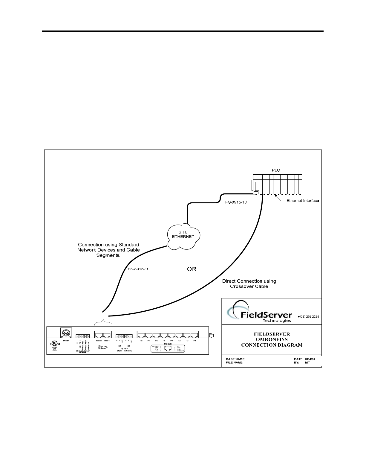
3. Hardware Connections
The FieldServer is connected to the PLC as shown in connection drawing.
Configure the PLC according to manufacturer’s instructions to work with other FINS
supported device.
1.03 Hardware Connection Tips / Hints
If communication doesn’t start check the following.
1. Are the FieldServer and PLC on the same network?
2. Are all intended Nodes configured to communicate on FINS?
3. Are all FINS Nodes configured to use the same Port Number?
FieldServer Technologies 1991 Tarob Court Milpitas, California 95035 USA Web:www.fieldserver.com
Tel: (408) 262-2299 Fax: (408) 262-9042 Toll_Free: 888-509-1970 email: support@fieldserver.com
Page 7
FS-8704-16 Omron FINS Manual Page 4 of 37
4. Is the Network healthy?
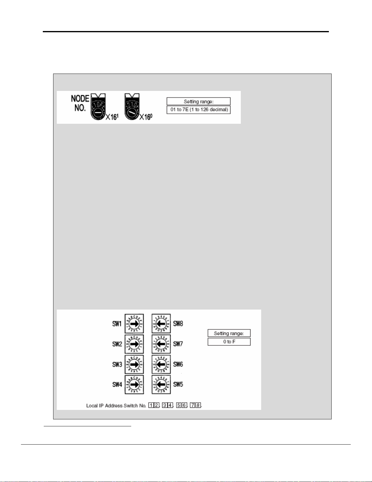
1.04 Example of Omron PLC Configuration using Omron ETN11 Module.1
Setting the Node Number
With the FINS communications service, when there are multiple Ethernet Units connected to the
Ethernet network, the Ethernet Units are identified by node numbers. Use the node number switches
to set the node number between 01 and 7E hexadecimal (1 to 126 decimal). Do not set a number
that has already been set for another node on the same network.
The left switch sets the sixteens digit (most significant digit) and the right switch sets the ones digit
(least significant digit). The node number is factory set to 01. When using the automatic generation
method for address conversion, set the node number to the same value as that of the local IP
address switches. If this is not possible, then either the IP address table method or the combined
method must be used for address conversion. For details, refer to 4-2 CPU
Bus Unit System Setup. If the FINS communications service is not being used over the Ethernet
network, then there is no problem if the node number duplicates that of another Ethernet Unit. The
node number must still be set from 01 to 7E, however, or the ERC indicator will light.
Note Turn OFF the power supply before setting the node number.
Setting the Local IP Address
The nodes on an Ethernet network are identified by IP addresses. Each IP address is set with 32 bits
of binary data. These 32 bits are divided into four 8- bit fields called octets, and each octet is
expressed as four decimal numbers. At CS-series Ethernet Units, four bits are expressed as a
hexadecimal digit, and the eight hexadecimal rotary switches (the local IP address switches) on the
back of the Unit are used to set the local IP address. Set the eight switches in hexadecimal as shown
below, combining SW1 and SW2, SW3 and SW4, SW5 and SW6, and SW7 and SW8. Each switch
can be set from 0 to F.
1
The following notes are extracted from the Omron Manual “W343-E1-05 9/03”
FieldServer Technologies 1991 Tarob Court Milpitas, California 95035 USA Web:www.fieldserver.com
Tel: (408) 262-2299 Fax: (408) 262-9042 Toll_Free: 888-509-1970 email: support@fieldserver.com
Page 8

FS-8704-16 Omron FINS Manual Page 5 of 37
The switches are all factory-set to 0 (00.00.00.00). The Ethernet Unit cannot be used with this
setting; a proper IP address must be set.
The following settings cannot be made for the IP address, or the ERC indicator will flash.
All bits in the network number field set to 0 or 1.
All bits in the host number field set to 0 or 1.
All bits in the subnet number field set to 1.
The beginning of the IP address set to 127 (7F Hex) Example: 127.35.21.16
Note 1. When using the automatic generation method for address conversion, set switches 7 and 8
to the same values as the node number setting, and set the rest of the host number to zeroes. For
details regarding the host number, refer to 1-7 IP Addresses. The value for the host number field in
the IP address must match the value for the node number or the ERC indicator will flash.
2. If a subnet mask is to be set, use the CX-Programmer to set it in the CPU Bus Unit System Setup.
For details, refer to 4-2 CPU Bus Unit System Setup.
FieldServer Technologies 1991 Tarob Court Milpitas, California 95035 USA Web:www.fieldserver.com
Tel: (408) 262-2299 Fax: (408) 262-9042 Toll_Free: 888-509-1970 email: support@fieldserver.com
Page 9

FS-8704-16 Omron FINS Manual Page 6 of 37
4. Configuring the FieldServer as a FINS Client
For a detailed discussion on FieldServer configuration, please refer to the FieldServer
Configuration Manual. The information that follows describes how to expand upon the
factory defaults provided in the configuration files included with the FieldServer (See
“.csv” sample files provided with the FieldServer).
This section documents and describes the parameters necessary for configuring the
FieldServer to communicate with a FINS Server. As a Client this driver reads and writes
data to Server Nodes. Server nodes should be FINS capable and be configured to
communicate over FINS
1.05 Data Arrays/Descriptors
The configuration file tells the FieldServer about its interfaces, and the routing of
data required. In order to enable the FieldServer for FINS communications, the
driver independent FieldServer buffers need to be declared in the “Data Arrays”
section, the destination device addresses need to be declared in the “Client Side
Nodes” section, and the data required from the servers needs to be mapped in the
“Client Side Map Descriptors” section. Details on how to do this can be found below.
Note that in the tables, * indicates an optional parameter, with the bold legal value
being the default.
Section Title
Data_Arrays
Column Title Function Legal Values
Data_Array_Name Provide name for Data Array
Provide data format. Each Data
Data_Array_Format
Array can only take on one
format.
Up to 15 alphanumeric
characters
Float, Bit, UInt16,
SInt16, Packed_Bit,
Byte, Packed_Byte,
Swapped_Byte
Number of Data Objects. Must
be larger than the data storage
Data_Array_Length
area required by the Map
1-32767
Descriptors for the data being
placed in this array.
FieldServer Technologies 1991 Tarob Court Milpitas, California 95035 USA Web:www.fieldserver.com
Tel: (408) 262-2299 Fax: (408) 262-9042 Toll_Free: 888-509-1970 email: support@fieldserver.com
Page 10

FS-8704-16 Omron FINS Manual Page 7 of 37
Example
// Data Arrays
Data_Arrays
Data_Array_Name, Data_Format, Data_Array_Length,
DA_CIO, UInt16, 5143
DA_WR, UInt16, 511
DA_HR, Uint16, 511
DA_DM, Uint16, 32767
1.06 Driver Specific FieldServer Parameters
Section Title
FieldServer
Column Title Function Legal Values
Title Name for FieldServer Text
Specify physical node Id on
network.
This is the last byte of the
IP Address of the
System_Node_Id
FieldServer. eg. If
1-126
FieldServer’s IP Address is
192.168.1.81 then this
parameter should be set to
81
Example
// FieldServer Driver specific parameters
FieldServer
Title, System_Node_Id
Fins Client, 81
1.07 Client Side Connection Descriptors
Section Title
Adapter
Column Title Function Legal Values
Adapter Adapter Name N1, N22
Protocol Specify protocol used Fins, omn_fins or fins_udp
Udp_port_number Specify UDP port number 0, 9600 etc
2
Not all ports shown are necessarily supported by the hardware. Consult the appropriate Instruction manual for
details of the ports available on specific hardware.
FieldServer Technologies 1991 Tarob Court Milpitas, California 95035 USA Web:www.fieldserver.com
Tel: (408) 262-2299 Fax: (408) 262-9042 Toll_Free: 888-509-1970 email: support@fieldserver.com
Page 11

FS-8704-16 Omron FINS Manual Page 8 of 37
Example
// Client Side
Connections
Adapters
Adapter, Protocol, Udp_port_number
N1, Fins, 9600
1.08 Client Side Node Descriptors
Section Title
Nodes
Column Title Function Legal Values
Node_Name Provide name for node
Up to 32 alphanumeric
characters
IP_Address Provide IP Address of PLC Eg. 192.168.1.105
Node number set at PLC
The node number should
Node_ID
correspond to the last byte of
1-126
the IP address. Eg. 105
corresponds to the example IP
address above.
Protocol Specify protocol used Fins, omn_fins or fins_udp
Adapter
*Net_Number
Specify which port the device is
connected to the FieldServer
Provide the network number of
PLC
N1, N23
1-255
Example
// Client Side Nodes
Nodes
Node_Name, IP_Address, Node_ID, Protocol, Adapter, Net_Number
PLC 1, 192.168.1.5, 1, Fins, N1, 1
3
Not all ports shown are necessarily supported by the hardware. Consult the appropriate Instruction manual for
details of the ports available on specific hardware.
FieldServer Technologies 1991 Tarob Court Milpitas, California 95035 USA Web:www.fieldserver.com
Tel: (408) 262-2299 Fax: (408) 262-9042 Toll_Free: 888-509-1970 email: support@fieldserver.com
Page 12

FS-8704-16 Omron FINS Manual Page 9 of 37
1.09 Client Side Map Descriptors
4.1.1. FieldServer Related Map Descriptor Parameters
Column Title Function Legal Values
Map_Descriptor_Na
me
Data_Array_Name
Data_Array_Offset
Function
Name of this Map
Descriptor
Name of Data Array
where data is to be
stored in the
FieldServer
Starting location in
Data Array
Function of Client Map
Descriptor
Up to 32 alphanumeric
characters
One of the Data Array names
from “Data Array” section
above
0 to maximum specified in
“Data Array” section above
RDBC, WRBC, WRBX
4.1.2. Driver Related Map Descriptor Parameters
Column Title Function Legal Values
One of the node names
specified in “Client Node
Descriptor” above
CIO-WORD, WR-WORD, HRWORD, AR-WORD, EMWORD
Node_Name
*Data_Type
(see Note 1
Appendix A.1)
Name of Node to fetch
data from
Data type
Length
Address
*Memory_Code
(see Note 1
Appendix A.1)
Command_Name
(see Note 2 section
6.1)
*MRC
(see Note 2
Appendix A.1)
*SRC
(see Note 2
Appendix A.1)
Length of Map
Descriptor
Starting address of
read block
Memory code for PLC
memory type
1- 729
0, 1,…100, etc
see Appendix A.1 for details
B0, B1, B2, B3, 82, 98 and
A0 ---- AC
MEMORY AREA READ
MEMORY AREA WRITE
RUN-STOP
Name of the command
CLOCK READ
CLOCK WRITE
CYCLE TIME READ
CPU UNIT STATUS READ
Main Request Code 1,4,6,7
Sub Request Code 1,2,20
FieldServer Technologies 1991 Tarob Court Milpitas, California 95035 USA Web:www.fieldserver.com
Tel: (408) 262-2299 Fax: (408) 262-9042 Toll_Free: 888-509-1970 email: support@fieldserver.com
Page 13

FS-8704-16 Omron FINS Manual Page 10 of 37
*Unit_Number
Unit number of CPU at
PLC
0,1,2 etc
4.1.3. Timing Parameters
Column Title Function Legal Values
Scan_Interval Rate at which data is polled ≥0.001s
FieldServer Technologies 1991 Tarob Court Milpitas, California 95035 USA Web:www.fieldserver.com
Tel: (408) 262-2299 Fax: (408) 262-9042 Toll_Free: 888-509-1970 email: support@fieldserver.com
Page 14

FS-8704-16 Omron FINS Manual Page 11 of 37
4.1.4. Map Descriptor Example 1 – IO Read
This example provides all the required information to read and write to the IO memory area of the PLC. The following Map
Descriptor creates a task for the driver to read the first 20 Words from the CIO memory area and store them in the Data
Array DA_CIO. The first word from the PLC will be stored as the first element in the Data Array. Whenever an upstream
device writes any element in the Data Array, the Driver will write the same value to the PLC at the corresponding address.
This scheme is known as Write-thru. In this example the Driver can write only one value at a time.
Map_Descriptor_Name, Data_Array_Name, Data_Array_Offset, Function, Node_Name Address, Length, Data_Type, Command_Name, Unit_number
CMD_CIO, DA_CIO, 0, RDBC, PLC1, 0, 20, CIO-WORD, MEMORY AREA READ, 0
One of the Data
Arrays declared in
the Data_Array
section
The Data for CIO
memory area from
the Node (PLC1)
will be stored in this
Data Array.
Forcing the Driver to issue a
read request for each
Scan_Interval .
In particular case Driver
will read this portion of CIO
memory area for each
second if Scan_Interval is set
1s.
Starting Address
of the memory
area to read.
Specifies the type of target
memory at PLC.
Also this parameter can be
replaced with
Memory_Code parameter.
See chapter 6 to for memory
codes read CIO Word area.
Unit number at PLC
Offset within the Data
Array at which Driver will
the store the data for initial
Address defined under
“Address” parameter.
In particular this case data
for Address 0 will be
stored at offset 0, for
Address 1 offset 1 and so
on.
Specify the number of
elements (number of Words
in this case) to read from
This is the logical name
of the target device
having the parameters
defined in section
“Client Node
Descriptors”.
FieldServer Technologies 1991 Tarob Court Milpitas, California 95035 USA Web:www.fieldserver.com
Tel: (408) 262-2299 Fax: (408) 262-9042 Toll_Free: 888-509-1970 email: support@fieldserver.com
PLC.
Command Name specifies the Main and
Sub request codes to make a request to
read this memory from PLC.
Assigning Direct MRC and SRC
parameters can replace this parameter.
See chapter 6 to know valid MRC –SRC
values to read this CIO memory area.
Page 15

FS-8704-16 Omron FINS Manual Page 12 of 37
4.1.5. Map Descriptor Example 2 – IO Write
This example is used to write a value(s) to the PLC. The write is done when the contents of the Data Array are updated
(written to by a remote device.). In the previous example, it was shown how a ‘read’ Map Descriptor can also be used to
write by using FIeldServer’s Write-Through technology.
Map_Descriptor_Name, Data_Array_Name, Data_Array_Offset, Function, Node_name Address, Length, Data_type, Command_Name, Unit_Number
CMD_CIOw, DA_CIOw, 0, WRBX, PLC1, 0, 20, CIO-WORD, MEMORY AREA WRITE, 0
One of the Data
Arrays declared in
the Data_Array
section (See section
1.05)
The Data in this
Data Array will be
written to the PLC1.
Driver will
fetch
consecutive 20
(Length)
elements
starting from
this offset to be
written at Node
PLC1
Forcing the Driver to issue a
write request upon updating
this dedicated portion of Data
Array. In this case first 20
elements comes under
dedicated portion for this map
descriptor.
Note : If WRBC , It will Force
the Driver to issue a write
request for each Scan_Interval
In this particular case Driver
will write this portion of CIO
memory area for each second.
Specify the
number of
elements
(number of
Words in this
case) to read
from PLC.
Specifies the type
of target memor y
at PLC.
Also this
parameter can be
replaced with
Memory_Code
parameter.
See Appendix A
to for memory
codes read CIO
Word area.
Command Name
specifies the
Main and Sub
request codes to
make a request to
write this
memory from
PLC.
Assigning Direct
MRC and SRC
parameters can
replace this
parameter.
See Appendix A
to know valid
MRC –SRC
values to read
this CIO memory
area.
Unit
number at
PLC
(Keep
mostly
zero, or
undefined
keep it
zero)
FieldServer Technologies 1991 Tarob Court Milpitas, California 95035 USA Web:www.fieldserver.com
Tel: (408) 262-2299 Fax: (408) 262-9042 Toll_Free: 888-509-1970 email: support@fieldserver.com
Page 16

FS-8704-16 Omron FINS Manual Page 13 of 37
4.1.6. Map Descriptor Example 3: Clock Read:
This Map Descriptor reads the PLC clock and stores the information in a Data Array DA_CLK. For detail on how the
Driver stores clock information see Appendix B.1.
Map_Descriptor_Name, Data_Array_Name, Data_Array_Offset, Function, Node_Name, Length, Command_Name, Unit_Number
CMD_CLKr, DA_CLKr, 0, RDBC, PLC1, 7, CLOCK READ, 0
4.1.7. Map Descriptor Example 4: Clock Write:
Write-thru is not possible for Clock write. A dedicated Map Descriptor is required to overwrite the PLC clock. This
Map Descriptor overwrites the clock whenever an upstream device updates the DA_CLKw Data Array. See Appendix
B.1 for details.
Map_Descriptor_Name, Data_Array_Name, Data_Array_Offset, Function, Node_Name, Length, Command_Name, Unit_Number
CMD_CLKw, DA_CLKw, 0, WRBX, PLC1, 7, CLOCK WRITE, 0
Note: All elements must be updated in DA_CLKw to set the clock as expected. Whenever any element updates, the
Driver will write all seven values to the PLC along with the one updated value. If all elements are updated by the
upstream device in a single operation then the Driver will also set the all elements at the PLC in a single operation.
4.1.8. Map Descriptor Example 5: Read CPU Cycle Times:
This Map Descriptor reads the CPU cycle time at the PLC and stores the data in a Data Array DA_CYCT. Average,
maximum and minimum cycle times will be stored in three consecutive locations starting with the location indicated by
the Data_Array_Offset parameter. See Appendix B.1
Map_Descriptor_Name, Data_Array_Name, Data_Array_Offset, Function, Node_Name, Length, Command_Name, Unit_Number
CMD_CYCT, DA_CYCT, 0, RDBC, PLC1, 3, CLOCK READ, 0s
The Driver stores these values as it gets them from the PLC. Scaling can provided to determine the unit in which the
value is stored. Default is 10 times milliseconds.
FieldServer Technologies 1991 Tarob Court Milpitas, California 95035 USA Web:www.fieldserver.com
Tel: (408) 262-2299 Fax: (408) 262-9042 Toll_Free: 888-509-1970 email: support@fieldserver.com
Page 17

FS-8704-16 Omron FINS Manual Page 14 of 37
4.1.9. Map Descriptor Example 6: Run-Stop PLC:
Defining this Map Descriptor Driver can change the PLC mode to STOP (Program), MONITOR or RUN mode. The
Driver issues a change mode command to the PLC whenever the value at the declared offset is updated.
Map_Descriptor_Name, Data_Array_Name, Data_Array_Offset, Function, Node_name Length Command_Name Unit_Number
CMD_RUN_ST, DA_RUN_ST, 0, WRBX, PLC1, 1, RUN-STOP 0s
The Driver will change PLC modes depending upon the value poked by the upstream device at offset (0 in this case).
See section Appendix B.1 for values corresponding to PLC modes.
4.1.10. Map Descriptor Example 7: Read CPU Status:
Defining this Map Descriptor Driver reads the CPU status and stores it in the Data Array DA_STATUS.
Map_Descriptor_Name, Data_Array_Name, Data_Array_Offset, Function, Node_name Length Command_Name Unit_Number
CMD_STATUS, DA_STATUS, 0, REBC, PLC1, 67, CPU UNIT STATUS READ 0s
The Driver stores the status information in the named Data Array at consecutive locations starting with
Data_Array_Offset.
See Appendix B.1 for further information.
FieldServer Technologies 1991 Tarob Court Milpitas, California 95035 USA Web:www.fieldserver.com
Tel: (408) 262-2299 Fax: (408) 262-9042 Toll_Free: 888-509-1970 email: support@fieldserver.com
Page 18

FS-8704-16 Omron FINS Manual Page 15 of 37
5. Configuring the FieldServer as a FINS Server
For a detailed discussion on FieldServer configuration, please refer to the FieldServer
Configuration Manual. The information that follows describes how to expand upon the
factory defaults provided in the configuration files included with the FieldServer (See
“.csv” files on the driver CD).
This section documents and describes the parameters necessary for configuring the
FieldServer to communicate with a FINS Client.
As a Server, the Driver responses to read requests and updates the FieldServer Data
Arrays with write requests from the Client.
The configuration file tells the FieldServer about its interfaces, and the routing of data
required. In order to enable the FieldServer for FINS communications, the driver
independent FieldServer buffers need to be declared in the “Data Arrays” section, the
FieldServer virtual node(s) needs to be declared in the “Server Side Nodes” section,
and the data to be provided to the clients needs to be mapped in the “Server Side Map
Descriptors” section. Details on how to do this can be found below.
Note that in the tables, * indicates an optional parameter, with the bold legal value being
the default.
1.010 Server Side Connection Descriptors
Section Title
Adapter
Column Title Function Legal Values
Adapter Adapter Name N1, N24
Protocol Specify protocol used Fins, omn_fins or fins_udp
Udp_port_number Specify UDP port number 0,9600 etc
Example
// Server Side
Connections
Adapters
Adapter, Protocol, Udp_port_number
N1, Fins, 9600
4
Not all ports shown are necessarily supported by the hardware. Consult the appropriate Instruction manual for
details of the ports available on specific hardware.
FieldServer Technologies 1991 Tarob Court Milpitas, California 95035 USA Web:www.fieldserver.com
Tel: (408) 262-2299 Fax: (408) 262-9042 Toll_Free: 888-509-1970 email: support@fieldserver.com
Page 19

FS-8704-16 Omron FINS Manual Page 16 of 37
1.011 Server Side Node Descriptors
Section Title
Nodes
Column Title Function Legal Values
Node_Name Provide name for node
Node_ID
Virtual Node number of FINS
server.
Protocol Specify protocol used
Up to 32 alphanumeric
characters
1-126
Fins, omn_fins or
fins_udp
Specifies time FieldServer
will reserve server side
Server_Hold_Timeout*
connection while waiting for
>1.0s
the Client side to update data
in Data_Array (if necessary)
Net_Number
Provide the network number
of FINS Server network
1-255
Example
// Server Side Nodes
Nodes
Node_Name, Node_ID, Protocol, Net_Numer
PLC 1, 1, Modbus_RTU, 1
FieldServer Technologies 1991 Tarob Court Milpitas, California 95035 USA Web:www.fieldserver.com
Tel: (408) 262-2299 Fax: (408) 262-9042 Toll_Free: 888-509-1970 email: support@fieldserver.com
Page 20

FS-8704-16 Omron FINS Manual Page 17 of 37
1.012 Server Side Map Descriptors
5.1.1. FieldServer Specific Map Descriptor Parameters
Column Title Function Legal Values
Map_Descriptor_Name
Data_Array_Name
Data_Array_Offset
Function
Name of this Map
Descriptor
Name of Data Array
where data is to be
stored in the FieldServer
Starting location in Data
Array
Function of Server Map
Descriptor
Up to 32 alphanumeric
characters
One of the Data Array names
from “Data Array” section
above
0 to maximum specified in
“Data Array” section above
Server
5.1.2. Driver Specific Map Descriptor Parameters
Column Title Function Legal Values
One of the node names
specified in “Server Node
Descriptor” above
CIO-WORD, WR-WORD,
HR-WORD, AR-WORD,
EM-WORD
Node_Name
*Data_Type
(see Note1 Appendix A.1)
Name of Node to fetch
data from
Data type
Length Length of Map Descriptor
*Address
*Memory_Code
(see Note1 Appendix A.1)
*Command_Name
(see Note2 Appendix A.1)
*MRC
(see Note2 Appendix A.1)
*SRC
(see Note2 Appendix A.1)
*Unit_Number
Starting address of read
block
Memory code for PLC
memory type
Name of the command
Main Request Code 1,4,6,7
Sub Request Code 1,2,20
Unit number of CPU at
PLC
1 to maximum specified in
Data Array section above
0,100, 32767 etc
see section 6.1 for detail
B0, B1, B2, B3, 82, 98 and
A0 ---- AC
MEMORY AREA READ
MEMORY AREA WRITE
RUN-STOP
CLOCK READ
CLOCK WRITE
CYCLE TIME READ
CPU UNIT STATUS READ
0,1,2 etc
FieldServer Technologies 1991 Tarob Court Milpitas, California 95035 USA Web:www.fieldserver.com
Tel: (408) 262-2299 Fax: (408) 262-9042 Toll_Free: 888-509-1970 email: support@fieldserver.com
Page 21
FS-8704-16 Omron FINS Manual Page 18 of 37
y
5.1.3. Map Descriptor Example 1: IO Read
The following Map Descriptor enables the Driver to serve the clients for CIO memory operations. The Command_Name
“MEMORY AREA READ” makes this memory readable.
Map_Descriptor_Name, Data_Array_Name, Data_Array_Offset, Function, Node_Name Address Length Data_Type Command_Name Unit_Number
SRV_CIOr, DA_CIO, 0, SERVER, PLC1, 0, 6143, CIO-WORD MEMORY AREA READ 0
One of the Data
Arrays declared in
the Data_Array
section.
Driver will serve
client for CIO
operations using this
Data Array.
Starting
location for data
within Data
Array
Specify the
Driver to Serve
Clients.
This is the
logical name of
the server device
having the
parameters
defined in section
“Server Node
Descriptors”.
Starting Address
of the memory
area to serve.
Specify the
number of
elements
(number of
Words in this
case) that this
Map
Descriptor
can serve.
Specifies the type
of memor y to
serve.
Also this
parameter can be
replaced with
Memory_Code
parameter.
See chapter 6 to
for memory
codes
Command Name
specifies the
Main and Sub
request codes to
make a request to
read this
memory.
Assigning Direct
MRC and SRC
parameters can
replace this
parameter.
See chapter 6 to
for MRC –SRC
values to enable
to read this CIO
memor
area.
FieldServer Technologies 1991 Tarob Court Milpitas, California 95035 USA Web:www.fieldserver.com
Tel: (408) 262-2299 Fax: (408) 262-9042 Toll_Free: 888-509-1970 email: support@fieldserver.com
Page 22

FS-8704-16 Omron FINS Manual Page 19 of 37
5.1.4. Map Descriptor Example 2: IO Write
This Map Descriptor makes the memory area writable which was made readable by the previous Map Descriptor.
Thus memory area can be made read only, write only or read and write enabled.
Map_Descriptor_Name, Data_Array_Name, Data_Array_Offset, Function, Node_Name Address Length Data_Type Command_Name Unit_number
SRV_CIOw, DA_CIO, 0, SERVER, PLC1, 0, 6143, CIO-WORD MEMORY AREA WRITE 0
5.1.5. Map Descriptor Example 3: Clock Read:
This Map Descriptor enables the Driver to serve the client with a Clock read request. See Appendix B.1for further
information
Map_Descriptor_Name, Data_Array_Name, Data_Array_Offset, Function, Node_Name Length Command_Name Unit_Number
SRV_CLKr, DA_CLKr, 0, SERVER, PLC1, 7, CLOCK READ 0s
5.1.6. Map Descriptor Example 4: Clock Write:
This Map Descriptor enables the Driver to update Clock information when the Client makes a Clock Write request. See
section Appendix B.1 for further information.
Map_Descriptor_Name, Data_Array_Name, Data_Array_Offset, Function, Node_name Length Command_Name Unit_Number
SRV_CLKr, DA_CLKr, 0, SERVER, PLC1, 7, CLOCK WRITE 0
5.1.7. Map Descriptor Example 5: CPU Cycle Times:
This Map Descriptor enables the Driver to serve Clients with CPU cycle time information upon request. See Appendix
B.1 for further information.
Map_Descriptor_Name, Data_Array_Name, Data_Array_Offset, Function, Node_Name Length Command_Name Unit_Number
SRV_CYCT, DA_CYCT, 0, SERVER, PLC1, 7, CLOCK READ 0
FieldServer Technologies 1991 Tarob Court Milpitas, California 95035 USA Web:www.fieldserver.com
Tel: (408) 262-2299 Fax: (408) 262-9042 Toll_Free: 888-509-1970 email: support@fieldserver.com
Page 23

FS-8704-16 Omron FINS Manual Page 20 of 37
5.1.8. Map Descriptor Example 6: Run-Stop PLC:
This Map Descriptor enables the Driver to give access to the Client to change the Server’s Operating Mode. See
Appendix B.1 for stored values corresponding to PLC modes.
Map_Descriptor_Name, Data_Array_Name, Data_Array_Offset, Function, Node_Name Length Command_Name Unit_Number
SRV_RUN_ST, DA_RUN_ST, 0, SERVER, PLC1, 1, RUN-STOP 0
5.1.9. Map Descriptor Example 7: CPU Status:
This Map Descriptor enables the Driver to respond to clients requesting CPU status. See Appendix B.1for further
information.
Map_Descriptor_Name, Data_Array_Name, Data_Array_Offset, Function, Node_Name Length Command_Name Unit_Number
SRV_STATUS, DA_STATUS, 0, SERVER, PLC1, 67, CPU UNIT STATUS READ 0
FieldServer Technologies 1991 Tarob Court Milpitas, California 95035 USA Web:www.fieldserver.com
Tel: (408) 262-2299 Fax: (408) 262-9042 Toll_Free: 888-509-1970 email: support@fieldserver.com
Page 24

FS-8704-16 Omron FINS Manual Page 21 of 37
Appendix A. Advanced Topics
Appendix A.1. Driver Map Descriptor Parameter’s Bounds
Most Map Descriptors need to know the following
The Data Type to
be read or written:
Specify Either
a) Data Type or
b) Memory Code.
This is how the driver determines which memory area of the
PLC must be processed. (For EM Banks you can only specify
the Memory_Code.)
The Command to
be executed
Specify either
a) The command name or
b) The MRC/SRC Pair.
Memory
Type
I/O
Memory
Data_Type Memory_Code Command_Name MRC SRC Address
CIO-WORD B0
WR-WORD B1
HR-WORD B2
AR-WORD B3
DM-WORD 82
98
EM-WORD
Not Available
(Use only
memory_code)
Present Current
EM Bank
A0-AC
(Any other EM
Bank)
MEMORY AREA
READ
MEMORY AREA
WRITE
MEMORY AREA
READ
MEMORY AREA
WRITE
MEMORY AREA
READ
MEMORY AREA
WRITE
MEMORY AREA
READ
MEMORY AREA
WRITE
MEMORY AREA
READ
MEMORY AREA
WRITE
MEMORY AREA
READ
MEMORY AREA
WRITE
MEMORY AREA
READ
MEMORY AREA
WRITE
1 1 0-6143
1 2 0-6143
1 1 0-511
1 2 0-511
1 1 0-511
1 2 0-511
1 1 0-959
1 2 448-959
1 1 0-32767
1 2 0-32767
1 1 0-32767
1 2 0-32767
1 1 0-32767
1 2 0-32767
FieldServer Technologies 1991 Tarob Court Milpitas, California 95035 USA Web:www.fieldserver.com
Tel: (408) 262-2299 Fax: (408) 262-9042 Toll_Free: 888-509-1970 email: support@fieldserver.com
Page 25
FS-8704-16 Omron FINS Manual Page 22 of 37
Appendix A.2. PLC status to execute commands
PLC Type
CS1/CJ1
Series
Memory
Type
I/O Memory
Mode
Changes
Access
Status
Reading
Command name
MEMORY AREA
READ
MEMORY AREA
WRITE
RUN OK OK OK Disabled OK OK Operating
STOP OK OK OK Disabled OK OK
CLOCK READ OK OK OK OK OK OK Time Data
CLOCK WRITE OK OK OK Disabled OK OK
CPU UNIT
STATUS READ
CYCLE TIME
READ
Run
Mode
OK OK OK OK OK OK
OK OK OK OK OK OK
OK OK OK OK OK OK
OK OK Disabled OK OK OK
Monitor
Mode
Program
Mode
Access
right 5
UM Read
Protection6
DIP UM
Protection7
5
Access Right at Other Device: The Access right at other device column tells whether the CPU Unit can or cannot receive a command when another device has
the access right to the CPU Unit.
6
UM Read Protection: The UM read protection column tells whether the CPU Unit can or cannot receive the command when UM (user memory) is protected
from a Peripheral Device.
7
DIP Switch UM Protection: The DIP switch UM protection column tells whether the CPU Unit can or cannot receive a command when UM is write-protected
by turning ON pin 1 of the DIP switch on the CPU Unit’s front panel.
FieldServer Technologies 1991 Tarob Court Milpitas, California 95035 USA Web:www.fieldserver.com
Tel: (408) 262-2299 Fax: (408) 262-9042 Toll_Free: 888-509-1970 email: support@fieldserver.com
Page 26

FS-8704-16 Omron FINS Manual Page 23 of 37
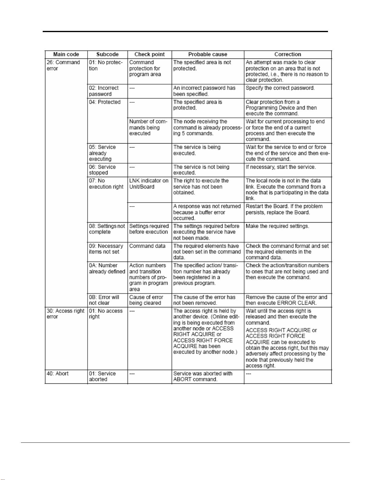
8
Appendix A.3. End Codes
The following table lists the main codes and the sub-codes, which combine to form
the end code (response code) returned for a FINS command. The probable cause
and corrections for each error code are also given. Depending on the command, the
destination code will sometimes make a request of another node on a network. The
other node is referred to as the third Node.
8
This section is a reproduction of Section 5-1-3 End Codes from Omron Communication Commands Reference
Manual (M11W342e160603.pdf)
FieldServer Technologies 1991 Tarob Court Milpitas, California 95035 USA Web:www.fieldserver.com
Tel: (408) 262-2299 Fax: (408) 262-9042 Toll_Free: 888-509-1970 email: support@fieldserver.com
Page 27

FS-8704-16 Omron FINS Manual Page 24 of 37
FieldServer Technologies 1991 Tarob Court Milpitas, California 95035 USA Web:www.fieldserver.com
Tel: (408) 262-2299 Fax: (408) 262-9042 Toll_Free: 888-509-1970 email: support@fieldserver.com
Page 28

FS-8704-16 Omron FINS Manual Page 25 of 37
FieldServer Technologies 1991 Tarob Court Milpitas, California 95035 USA Web:www.fieldserver.com
Tel: (408) 262-2299 Fax: (408) 262-9042 Toll_Free: 888-509-1970 email: support@fieldserver.com
Page 29

FS-8704-16 Omron FINS Manual Page 26 of 37
FieldServer Technologies 1991 Tarob Court Milpitas, California 95035 USA Web:www.fieldserver.com
Tel: (408) 262-2299 Fax: (408) 262-9042 Toll_Free: 888-509-1970 email: support@fieldserver.com
Page 30

FS-8704-16 Omron FINS Manual Page 27 of 37
FieldServer Technologies 1991 Tarob Court Milpitas, California 95035 USA Web:www.fieldserver.com
Tel: (408) 262-2299 Fax: (408) 262-9042 Toll_Free: 888-509-1970 email: support@fieldserver.com
Page 31

FS-8704-16 Omron FINS Manual Page 28 of 37
FieldServer Technologies 1991 Tarob Court Milpitas, California 95035 USA Web:www.fieldserver.com
Tel: (408) 262-2299 Fax: (408) 262-9042 Toll_Free: 888-509-1970 email: support@fieldserver.com
Page 32
FS-8704-16 Omron FINS Manual Page 29 of 37
FieldServer Technologies 1991 Tarob Court Milpitas, California 95035 USA Web:www.fieldserver.com
Tel: (408) 262-2299 Fax: (408) 262-9042 Toll_Free: 888-509-1970 email: support@fieldserver.com
Page 33
FS-8704-16 Omron FINS Manual Page 30 of 37
Appendix B. Driver Notes
Appendix B.1. Data Storage
Clock Information
Element Contents
1 Year (4 for 2004, 12 for 2012)
2 Month
3 Day of Month
4 Hours
5 Minutes
6 Seconds
7 Day of the week (Sunday = 0, Saturday=6)
CPU Cycle Time
Element Contents
1 Average Cycle Time
2 Maximum Cycle Time
3 Minimum Cycle Time
PLC Mode
Stored Value PLC Mode
1 STOP
2 MONITOR
3 RUN
CPU Status
FieldServer Technologies 1991 Tarob Court Milpitas, California 95035 USA Web:www.fieldserver.com
Tel: (408) 262-2299 Fax: (408) 262-9042 Toll_Free: 888-509-1970 email: support@fieldserver.com
Page 34

FS-8704-16 Omron FINS Manual Page 31 of 37
ELEMENT
NUMBER
CONTENTS DESCRIPTION
CPU Status9
1
1
2
3
1= Stop
2= Standby (waiting for signal from another
Device)
3= Run
CPU Mode
1= PROGRAM
2= MONITOR
3= RUN
2
1
2
3
3 1/0 1: Memory Error
4 1/0 1: I/O Bus Error
5 1/0 1:Duplication Error
6 1/0 1:Fatal Inner Board Error
7 1/0 1:I/O Point overflow
8 1/0 1:I/O Setting Error
9 1/0 1:Program Error
10 1/0 1:Cycle Time Over
11 0 12 1/0 1:FALS Error
13-18 0 19 1/0 1:FAL Error
20 Unknown Reserved for System
21 1/0 1:Interrupt Task Error
22 1/0 1:Basic I/O Unit Error
23 Unknown Reserved for System
24 1/0 1:PLC Setup Error
25 1/0 1:I/O Verification Error
26 1/0 1:Inner Board Error
27 1/0 1:CPU Bus Unit Error
28 1/0 1:Special I/O Unit Error
29 1/0 1:Sysmac Bus Error
30 1/0 1:Battery Error
31 1/0 1:CPU Bus Unit Setting Error
32 1/0 1:Special I/O Unit-Setting Error
33-34 Unknown Reserved for System
35-42 0 -
9
PLC Value Driver Value Meaning
0x00 1 Stop
0x80 2 Standby
0x01 3 Run
Note: During testing it has been found that the PLC Value corresponds with this book value. Hence the Driver
stores or sends any other value as it is. User has to do some experiment on it.
FieldServer Technologies 1991 Tarob Court Milpitas, California 95035 USA Web:www.fieldserver.com
Tel: (408) 262-2299 Fax: (408) 262-9042 Toll_Free: 888-509-1970 email: support@fieldserver.com
Page 35

FS-8704-16 Omron FINS Manual Page 32 of 37
ELEMENT
NUMBER
CONTENTS DESCRIPTION
43 1/0 1:Message # 7 Present
44 1/0 1:Message # 6 Present
45 1/0 1:Message # 5 Present
46 1/0 1:Message # 4 Present
47 1/0 1:Message # 3 Present
48 1/0 1:Message # 2 Present
49 1/0 1:Message # 1 Present
50 1/0 1:Message # 0 Present
51 0-65535 Error Code
52-67 A-Z 16 Character Text
Appendix B.2. Driver stats
In addition to the standard FieldServer operating statistics the driver exposes certain
key stats in a Data Array if required. An upstream device can then monitor these
stats.
Add the following to your configuration file to activate these stats.
// Expose Driver Operating Stats.
Data_Arrays
Data_Array_Name, Data_Format, Data_Array_Length
fins-stats, UINT32, 200
Stat
Number
0 FINS_BAD_START
1 FINS_NET
2 FINS_STATION
3 FINS_UNIT
4 FINS_MRC
5 FINS_SRC
6 FINS_SID
Stats Description
Number of Messages received with bad start
byte.
Number of Messages received with bad or
unsupported Network Number.
Number of Messages received with bad or
unsupported Node Number.
Number of Messages received with bad or
unsupported Unit Number.
Number of Messages received with bad or
unsupported Main Request Code
Number of Messages received with bad or
unsupported Sub Request Code
Number of Messages received with wrong or
Sequence Id.
FieldServer Technologies 1991 Tarob Court Milpitas, California 95035 USA Web:www.fieldserver.com
Tel: (408) 262-2299 Fax: (408) 262-9042 Toll_Free: 888-509-1970 email: support@fieldserver.com
Page 36

FS-8704-16 Omron FINS Manual Page 33 of 37
7 FINS_ECODE
Total number of Messages ignored by PLC due to
error.
8 FINS_EMC Latest Main Error code returned by PLC.
9 FINS_ESC Latest Sub Error code returned by PLC.
10 FINS_EMRC
11 FINS_ESRC
12 FINS_STOR_SP
13 FINS_NO_WR_THU
Main and Sub Request codes for which PLC
returned Error Code.
Number of times Driver ignored messages
because of insufficient storage space.
Number of blocked attempts to write data via
write-thru operation.
Appendix B.3. Driver Error Messag es
Some configuration errors might produce an error every time a poll is generated.
This will fill the error buffer quickly and not add any clarity. For this reason the driver
suppresses subsequent similar messages on the System Error Screen. Thus it is
possible for the same error produced by multiple Map Descriptors to produce only
one error message on the System Error screen. The driver displays subsequent
error messages on the Driver Messages screen.
Note : In the actual message you will see that %d has been replaced by an integer,
%s by text indicating a data array name or map descriptor name and %x by two hex
characters.
Error Message Description and Action Required
FINS_UDP#1: Err. Not Enough
Space for <%d> items.
When offset <%d> DA <%s> MD
Data array length needs to be increased.10
<%s>
MRC <%2X> SRC<%2X>
FINS_UDP#2: Err. MD <%s>.
Error Returned by PLC.
MRC <%2X> SRC<%2X>
Main End Code <%2X> Sub End
Code <%2X>
This message shows a request that produced
this error at the PLC. Check Appendix A.1 to
see the detail for error and action.
See Driver Manual for End Codes
detail...
FINS_UDP#3: FYI. MRC<%2X>
SRC<%2X> Not Supported
FINS_UDP#11: Err. Station
Reqd/Ext <%d/%d>
This command is not supported by the Driver.
Response from PLC is not addressed to this
Client.
10
Some error messages require that the user correct a problem in the configuration. This is done by editing the
configuration CSV file, downloading the modified file and resetting the FieldServer to have the changes take effect.
FieldServer Technologies 1991 Tarob Court Milpitas, California 95035 USA Web:www.fieldserver.com
Tel: (408) 262-2299 Fax: (408) 262-9042 Toll_Free: 888-509-1970 email: support@fieldserver.com
Page 37

FS-8704-16 Omron FINS Manual Page 34 of 37
Error Message Description and Action Required
FINS_UDP#12: Err. Mrc-Src
Reqd/Ext <%2X-%2X/%2X-%2X>
Response from PLC not for current request.
FINS_UDP#21: Err. Message from
PLC is Not a Response>
MRC <%2X> SRC <%2x> MD
Message from PLC for shown request is not a
response.
<%s>
FINS_UDP#22: Err. Unknown
Device with Parameters...
Reqd/Ext dna <%d/%d> node
Response from PLC ignored because
mismatching for any shown parameters.
<%d/%d> unit <%d/%d>
FINS_UDP#23: Err. Message
Sequence Not Matched.Reqd/Ext
<%d/%d>
MRC <%2X> SRC <%2X> MD
Response from PLC ignored because of
mismatching request-response sequence Id.
<%s>
FINS_UDP#24: FYI. Bad
Start<%2X>
FINS_UDP#31 : FYI Net_Number
set to 1 Node <%s>
FINS_UDP#32 : FYI Udp Port is
<%d>
FINS_UDP#41: FYI. Write-thru not
Possible On MD <%s>
The message was ignored because the first
byte was bad.
The Net_Number parameter is 0 or not
specified. The Driver will automatically
change it to the default of 1
Information about UDP Port number in use.
Upstream device tried Write-thru operation on
other than IO memory area.
FINS_UDP:#51 FYI. You could
have used an Array called <%s>
to expose diagnostic info. Read
Define an array to expose stats if required.
See Appendix B.1
Manual.
FieldServer Technologies 1991 Tarob Court Milpitas, California 95035 USA Web:www.fieldserver.com
Tel: (408) 262-2299 Fax: (408) 262-9042 Toll_Free: 888-509-1970 email: support@fieldserver.com
Page 38

FS-8704-16 Omron FINS Manual Page 35 of 37
Appendix C. Troubleshooting tips
Appendix C.1. Connection Tips & Hints
1. Each transaction must be completed in one UDP message fragment. The
maximum length of a UDP fragment is 1500 bytes. Thus, if you wanted to read
730 words of PLC memory you will need to configure two MD’s. The one should
have a length of 729 and the other a length of 1. The reason is that when the
length is set to 729, then 729 words (or 1500 bytes including FINS and UDP
header) of data are read and this is the maximum for one message fragment.
Similarly as a Server, the Driver can handle transactions composed of a
maximum 1500 bytes (or 729 Words).
2. Ensure that the IP Address of the PLC provided under IP_Address parameter in
configuration is correct
3. Ensure the Node number of the FieldServer on the network is mentioned under
System_Node_Id parameter in configuration file
4. Ensure that the “Udp_port_number” parameter has the correct value in the
configuration file
5. Omron PLC's respond to remote FINS polls by sending UDP response messages
on the ethernet network. The PLC does not use the IP address of the incoming
poll to determine the IP address it must respond to. The PLC builds the IP
address it will send the response to using
1) Its own IP address and the Node ID of the polling device or
2) A routing table built using Omron software. To find out more information
consult the Omron Manaul W343-E1-3, Chapter 3 provides more information.
When the PLC uses its own IP address to build the IP address it will send the
response to, then special consideration should be taken if the PLC IP address is
Class A or B.
On a Class B network, the PLC uses the 1st two bytes of its own IP address, sets
the 3rd byte to zero and sets the 4th byte equal to the polling station's Node_Id.
Example: - Class B Addressing
A FieldServer with IP address=192.168.1.81 and system_node_id=34 polls for
data from a PLC with IP address =192.168.2.33 and Subnet mask = 255.255.0.0
The PLC responds to 192.168.2.33
255.255.0.0
192.168.x.y
Where x is always set to zero and
y is equal to 34 (The PLC obtains the node ID of 34 by
inspecting the contents of the poll message.)
FieldServer Technologies 1991 Tarob Court Milpitas, California 95035 USA Web:www.fieldserver.com
Tel: (408) 262-2299 Fax: (408) 262-9042 Toll_Free: 888-509-1970 email: support@fieldserver.com
Page 39

FS-8704-16 Omron FINS Manual Page 36 of 37
Therefore the PLC responds to 192.168.0.34 which is clearly the wrong address
and the FieldServer will not see the response.
Example: - Class A Addressing
A FieldServer with IP address=192.168.1.81 and system_node_id=34 polls for
data from a PLC with IP address =192.168.2.33 and Subnet mask = 255.255.0.0
The PLC responds to 192.168.2.33
255.0.0.0
192.x.x.y
Where x is always set to zero and
y is equal to 34 (The PLC obtains the node ID of 34 by
inspecting the contents of the poll message.)
Therefore the PLC responds to 192.0.0.34 which is clearly the wrong address
and the FieldServer will not see the response.
Thus, if the PLC is using Class A/B IP addressing then the 3rd (Class B) or the
2nd and 3rd (Class A) bytes of the address must be zero as must the
FieldServer's if communications are to work.
There are ways around this problem, we believe. The solution requires usage of
the Omron PLC routing table. For more help consult with Omron's Tech Support.
FieldServer Technologies 1991 Tarob Court Milpitas, California 95035 USA Web:www.fieldserver.com
Tel: (408) 262-2299 Fax: (408) 262-9042 Toll_Free: 888-509-1970 email: support@fieldserver.com
Page 40

FS-8704-16 Omron FINS Manual Page 37 of 37
Appendix D. Revision History
Date Resp Format
Driver
Ver.
Doc.
Rev.
Comment
4/17/04 SSS 0.00 0 Issued for PMC review.
Reviewed and made some reference
4/20/04 PMC 0.00 1
changes, some type changes, changed
some wording and included Omron manual
excerpts for IP address setting.
Changed section 7.1.4, Value from PLC
does not agree with book value. Updated
4/20/04 SSS 0.00 2
section 8.1 Maximum words are 729 Not
750. This is the limit for one UDP message
fragment because of FINS and UDP
header.
4/20/04 SSS 0.00 2 Issued for Release.
Reformatted document. Changed
5/20/04 Meg Meg 0.00 3
language and grammar. Improved
readability of document. Updated
according to DUR0356
6/14/04 JD 0.00 4 Releasing
Updated according to DUR0372. Changed
8/26/04 Meg Meg 0.00 5
Appendix numbers to letters and updated
cross referencing.
12/29/04 JD 0.00 6 Releasing
FieldServer Technologies 1991 Tarob Court Milpitas, California 95035 USA Web:www.fieldserver.com
Tel: (408) 262-2299 Fax: (408) 262-9042 Toll_Free: 888-509-1970 email: support@fieldserver.com
 Loading...