

Page 1
APPLICABILITY & EFFECTIVITY
Effective for all systems manufactured after January 2009
Driver Manual
(Supplement to the FieldServer Instruction Manual)
FS-8704-14 EtherNet/IP
Driver Version:
1.03
Document Revision:
3
A Sierra Monitor Company
Page 2

FS-8704-14 EtherNet/IP Manual Table of Contents
TABLE OF CONTENTS
1 EtherNet/IP Description ................................................................................................................................. 4
1.1 ODVA Status. .................................................................................................................................................. 4
2 Driver Scope of Supply ................................................................................................................................... 4
2.1 Supplied by FieldServer Technologies for this driver ..................................................................................... 4
3 Hardware Connections ................................................................................................................................... 5
4 Configuring the FieldServer as an EtherNet/IP Client ..................................................................................... 6
4.1 Data Arrays/Descriptors ................................................................................................................................ 6
4.2 Client Side Connection Descriptions .............................................................................................................. 7
4.3 Client Side Node Descriptors ......................................................................................................................... 7
4.4 Client Side Map Descriptors........................................................................................................................... 8
4.4.1 FieldServer Related Map Descriptor Parameters ................................................................................... 8
4.4.2 Driver Related Map Descriptor Parameters – Unconnected Messages ................................................. 8
4.4.3 Driver Related Map Descriptor Parameters – Data Table Read/Write. ................................................. 9
4.4.4 Driver Related Map Descriptor Parameters – PCCC ............................................................................. 10
4.4.5 Timing Parameters ............................................................................................................................... 10
4.4.6 Map Descriptor Example 1: Unconnected Messages ........................................................................... 11
4.4.7 Map Descriptor Example 2: Data Table Messages .............................................................................. 11
4.4.8 Map Descriptor Example 3: PCCC Messages ........................................................................................ 11
5 Configuring the FieldServer as an EtherNet/IP Server .................................................................................. 12
5.1 Server Side Connection Descriptors ............................................................................................................ 12
5.2 Server Side Node Descriptors3 ..................................................................................................................... 13
5.3 Server Side Map Descriptors........................................................................................................................ 13
5.3.1 FieldServer Specific Map Descriptor Parameters ................................................................................. 13
5.3.2 Server Specific Map Descriptor Parameters – Unconnected Messages ............................................... 14
5.3.3 Server Specific Map Descriptor Parameters – Data Table Read/Write. ............................................... 14
5.3.4 Driver Related Map Descriptor Parameters – PCCC ............................................................................. 15
5.3.5 Map Descriptor Example 1: Unconnected Messages ........................................................................... 16
5.3.6 Map Descriptor Example 2: Data Table Messages .............................................................................. 16
5.3.7 Map Descriptor Example 3: PCCC Messages ........................................................................................ 16
Appendix A. Advanced Topics .............................................................................................................................. 17
Appendix A.1. General Notes .................................................................................................................................. 17
Appendix A.2. FieldServer as an Adapter and Scanner. ........................................................................................... 17
Appendix A.3. Common Paths ................................................................................................................................. 17
Appendix A.4. Setting the Data Type for stored data. ............................................................................................. 17
Appendix A.5. Configuring a PLC to read and write data to and from FieldServer.................................................. 17
Appendix A.5.1. FieldServer Configuration File ................................................................................................ 18
Appendix A.5.2. The PLC Program .................................................................................................................... 19
Appendix A.6. Configuring a FieldServer to read and write Data to and from a PLC. ............................................. 21
Appendix A.6.1. FieldServer Configuration File ................................................................................................ 22
Appendix A.6.2. The PLC Program .................................................................................................................... 23
Appendix A.7. Read/write structures and value of EIP_Structure_Handle : ........................................................... 23
Appendix A.8. Classes and Attributes Supported .................................................................................................... 25
Appendix A.9. Error Codes ....................................................................................................................................... 27
FieldServer Technologies 1991 Tarob Court Milpitas, California 95035 USA Web: www.fieldserver.com
Tel: (408) 262 2299 Fax: (408) 262 2269 Toll Free: (888) 509 1970 email: support@fieldserver.com
Page 3

FS-8704-14 EtherNet/IP Manual Table of Contents
Appendix B. Troubleshooting Tips ....................................................................................................................... 29
Appendix B.1. Firmware Update Downloading ....................................................................................................... 29
Appendix B.2. Connection information – Allen Bradley Message Blocks ................................................................ 29
Appendix B.3. FieldServer not recognised by RSlinx................................................................................................ 29
Appendix C. Error Messages ................................................................................................................................ 30
FieldServer Technologies 1991 Tarob Court Milpitas, California 95035 USA Web: www.fieldserver.com
Tel: (408) 262 2299 Fax: (408) 262 2269 Toll Free: (888) 509 1970 email: support@fieldserver.com
Page 4
FS-8704-14 EtherNet/IP Manual Page 4 of 30
Vendor Code
875
Product Type Code
12 or “Communications Adapter”
FieldServer Technologies PART #
Description
FS-8915-10
UTP cable (7 foot) for Ethernet connection
FS-8704-14
Driver Manual
1 ETHERNET/IP DESCRIPTION
The Ethernet IP driver allows the FieldServer to transfer data to and from devices over Ethernet using the
EtherNet/IP protocol. The FieldServer can emulate either a Server or Client.
EtherNet/IP uses CIP (Control and Information Protocol), the common network, transport and application layers
also shared by ControlNet and DeviceNet. EtherNet/IP then makes use of standard Ethernet and TCP/IP
technology to transport CIP communications packets. The result is a common, open application layer on top of
open and highly popular Ethernet and TCP/IP protocols.
The Driver is able to read/write using the Data Table structure employed by all Logix Series PLC’s.
PCCC support is also provided for legacy devices that do not fully support CIP encapsulation. EIP PCCC
Encapsulation was tested at FST factory using PLC5 I785 ENET card. The following data types were tested:
N
F
S
The information that follows describes how to expand upon the factory defaults provided in the configuration files
included with the FieldServer.
1.1 ODVA Status.
ODVA is an international association comprised of members from the world's leading automation companies.
Collectively, ODVA and its members support network technologies based on the Common Industrial Protocol
(CIP™). These currently include DeviceNet™, EtherNet/IP™, CIP Safety™ and CIP Sync™. ODVA manages the
development of these open technologies, and assists manufacturers and users of CIP-based networks through
tools, training and marketing activities.
FieldServer Technologies is an ODVA member and our device is ODVA tested to be Ethernet/IP Compliant.
2 DRIVER SCOPE OF SUPP LY
2.1 Supplied by FieldServer Technologies for this driver
FieldServer Technologies 1991 Tarob Court Milpitas, California 95035 USA Web: www.fieldserver.com
Tel: (408) 262 2299 Fax: (408) 262 2269 Toll Free: (888) 509 1970 email: support@fieldserver.com
Page 5
FS-8704-14 EtherNet/IP Manual Page 5 of 30
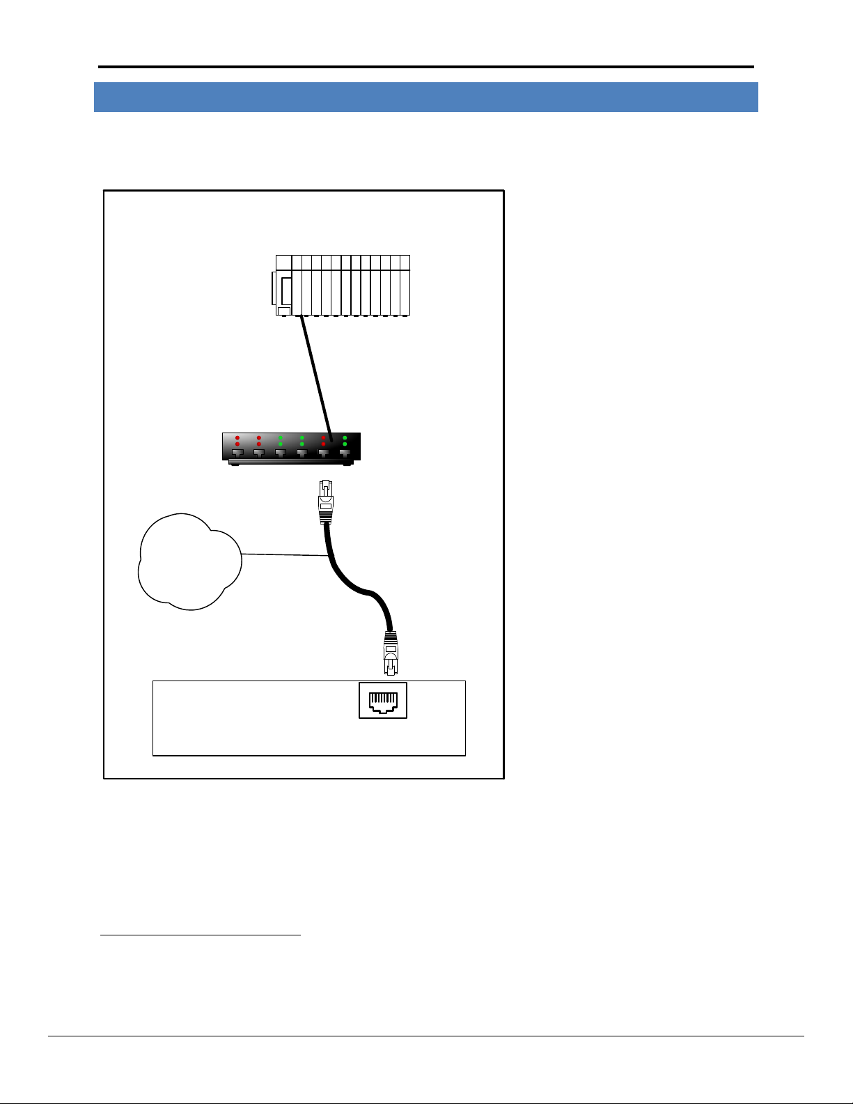
FieldServer
FieldServer Part #
8915-10
UTP cable
Connect to an Ethernet Port
on the FieldServer
N1
18
Hub/Router
Remote Ethernet/IP
Device
3 HARDWARE CONNECTIONS
It is possible to connect an EtherNet/IP device to either port N1 or N21 on the FieldServer. These ports must just
be configured to use EtherNet/IP in the configuration file.
1
Not all ports shown are necessarily supported by the hardware. Consult the appropriate Instruction manual for details of the ports available
on specific hardware.
FieldServer Technologies 1991 Tarob Court Milpitas, California 95035 USA Web: www.fieldserver.com
Tel: (408) 262 2299 Fax: (408) 262 2269 Toll Free: (888) 509 1970 email: support@fieldserver.com
Page 6

FS-8704-14 EtherNet/IP Manual Page 6 of 30
Section Title
Data_Arrays
Column Title
Function
Legal Values
Data_Array_Name
Provide name for Data Array
Up to 15 alphanumeric
characters
Data_Array_Format
Provide data format. Each Data Array
can only take on one format.
Float, Bit, UInt16, SInt16,
Packed_Bit, Byte,
Packed_Byte, Swapped_Byte
Data_Array_Length
Number of Data Objects. Must be larger
than the data storage area required by
the Map Descriptors for the data being
placed in this array.
1-10,000
// Data Arrays
Data_Arrays
Data_Array_Name
,Data_Format
,Data_Array_Length
DA_AI_01
,UInt16
,200
DA_AO_01
,UInt16
,200
DA_DI_01
,Bit
,200
DA_DO_01
,Bit
,200
4 CONFIGURING THE FIELDSERVER AS AN ETHERNET/IP CLIENT
For a detailed discussion on FieldServer configuration, please refer to the FieldServer Configuration Manual. The
information that follows describes how to expand upon the factory defaults provided in the configuration files
included with the FieldServer.
This section documents and describes the parameters necessary for configuring the FieldServer to communicate
with an EtherNet/IP Server.
4.1 Data Arrays/D escriptors
The configuration file tells the FieldServer about its interfaces, and the routing of data required. In order to enable
the FieldServer for EtherNet/IP communications, the driver independent FieldServer buffers need to be declared in
the “Data Arrays” section, the destination device addresses need to be declared in the “Client Side Nodes” section,
and the data required from the servers needs to be mapped in the “Client Side Map Descriptors” section. Details
on how to do this can be found below.
Note that in the tables, * indicates an optional parameter, with the bold legal value being the default.
Example
FieldServer Technologies 1991 Tarob Court Milpitas, California 95035 USA Web: www.fieldserver.com
Tel: (408) 262 2299 Fax: (408) 262 2269 Toll Free: (888) 509 1970 email: support@fieldserver.com
Page 7
FS-8704-14 EtherNet/IP Manual Page 7 of 30
Section Title
Adapter
Column Title
Function
Legal Values
Adapter
Adapter Name
N1, N2
2
Protocol
Specify protocol used
EtherNet/IP
// Client Side Connections
Adapters
Adapter
,Protocol
N1
,EtherNet/IP
Section Title
Nodes
Column Title
Function
Legal Values
Node_Name
Provide name for node
Up to 32 alphanumeric characters
IP_Address
Address of Server
Any valid address on subnet
Protocol
Specify protocol used
EtherNet/IP
Adapter
Specify port Adapter used
N1, N22
// Client Side Nodes
Nodes
Node_Name
,IP_Address
,Adapter
,Protocol
PLC 1
,192.168.1.174
,N1
,EtherNet/IP
4.2 Client Side Conne ction Des criptions
Example
4.3 Client Side Node Descriptors
Example
3
2
Not all ports shown are necessarily supported by the hardware. Consult the appropriate Instruction manual for details of the ports available
on specific hardware.
3
Only one explicit connection is created per node. All explicit Map Descriptors attached to that node will use the same explicit connection.
FieldServer Technologies 1991 Tarob Court Milpitas, California 95035 USA Web: www.fieldserver.com
Tel: (408) 262 2299 Fax: (408) 262 2269 Toll Free: (888) 509 1970 email: support@fieldserver.com
Page 8

FS-8704-14 EtherNet/IP Manual Page 8 of 30
Column Title
Function
Legal Values
Map_Descriptor_Name
Name of this Map Descriptor
Up to 32 alphanumeric characters
Data_Array_Name
Name of Data Array where data is to be
stored in the FieldServer
One of the Data Array names from “Data
Array” section above
Data_Array_Offset
Starting location in Data Array
0 to maximum specified in “Data Array”
section above
Function
Function of Client Map Descriptor
Rdbc, Wrbc, Wrbx
Column Title
Function
Legal Values
EIP_Service
The action to be performed.
Get_Attrib, Set_Attrib
EIP_Class
Class to be polled.
One of the classes supported by
the driver. Refer to Appendix A.4
EIP_Attribute
Attribute associated with the class given.
See particular attributes of each
class. Refer to Appendix A.4
EIP_Con_Typ
The type of data transfer required. Also referred to as the
“Transport Method”
Unconnected
Explicit
EIP_Path*
Used to stipulate the path to the CPU in certain PLC’s. Paths
vary and are dependent on the structure of the network.
Any space delimited numerical
value. Refer to vendor’s device
documentation. Also see
Appendix A.3, 0 0
Length
Number of data elements to be mapped. If the number of
data elements exceeds the Map Descriptor length, the list of
data elements will be truncated and an error message will be
printed once per Map Descriptor. Refer to Appendix C for
further information.
For any given Map Descriptor
there can be 200 Floats, 400
Integers or 800 Bytes
Address
Instance of the class to be polled.
Depends on the supported
instances for each class.
4.4 Client Side Map Descriptor s
4.4.1 FieldServer Related Map D escriptor Pa rameters
4.4.2 Driver Related Map Descriptor Parameters – Unconnecte d Messages
FieldServer Technologies 1991 Tarob Court Milpitas, California 95035 USA Web: www.fieldserver.com
Tel: (408) 262 2299 Fax: (408) 262 2269 Toll Free: (888) 509 1970 email: support@fieldserver.com
Page 9

FS-8704-14 EtherNet/IP Manual Page 9 of 30
Column Title
Function
Legal Values
EIP_Service
The action to be performed.
Data_Table_Read,
Data_Table_Write
EIP_Con_Typ
The type of data transfer required.
Explicit
EIP_Path*
Used to stipulate the path to the CPU in certain PLC’s.
Paths vary and are dependent on the structure of the
network.
Any space delimited
numerical value. Refer to
vendor’s device
documentation. Also see
Appendix A.3, 0 0
EIP_Tag_Name
Tag name expressed in PLC program. The data type of
this parameter is used to set the data format of the Data
Array if the EIP_DATA_TYPE parameter is not specified.
Maximum length 48
characters.
EIP_Data_Type*
If the parameter is specified, the data will be stored in
the specified format which may be different to the
format of the tag being polled. If the parameter is not
set, the Data Type of the Data Array will be used. This
parameter is only applicable to Data Table Write when
FieldServer is the Client. The Data Type of the Data
Array will be used for Data Table Reads when the
FieldServer is the Client. Refer to Appendix A.4 for more
information.
Float, Uint16, Uint32, Bit,
Byte, Boolean, -
Length
Number of data elements to be mapped. If the number
of data elements exceeds the Map Descriptor length, the
list of data elements will be truncated and an error
message will be printed once per Map Descriptor. See
Appendix C for further information.
For any given Map
Descriptor there can be 200
Floats, 400 Integers or 800
Bytes
EIP_Structure_Handle*
This parameter is required to read/write structures. The
driver supports read/write structures having members of
same type, i.e. all members are of type Byte, UINT16,
UINT32 or Float etc
When this parameter is defined, the number of structure
members must be specified as the length of the Map
Descriptor. Refer to Appendix A.7 for more information.
Any 16bit Integer number
(e.g. 59592), 0
4.4.3 Driver Related Map Descriptor Parameters – Data Table Read/Write.
FieldServer Technologies 1991 Tarob Court Milpitas, California 95035 USA Web: www.fieldserver.com
Tel: (408) 262 2299 Fax: (408) 262 2269 Toll Free: (888) 509 1970 email: support@fieldserver.com
Page 10

FS-8704-14 EtherNet/IP Manual Page 10 of 30
Column Title
Function
Legal Values
EIP_Service
Action to be performed
Exec_PCCC (Encapsulation using
Allen Bradley PCCC)
EIP_Con_Typ
The type of data transfer required
Explicit
EIP_Path*
Used to stipulate the path to the CPU in certain PLC’s. Paths
vary and are dependent on the structure of the network.
Any space delimited numerical
value. Refer to vendor’s device
documentation. Also see
Appendix A.3, 0 0
File_Type
Allen Bradley file type
N Integer
F Float
O Output
B Boolean
I Input
S Status
File_Number
Allen Bradley file number
Any valid numerical value
Length
Number of data elements to be mapped. If the number of
data elements exceeds the Map Descriptor length, the list of
data elements will be truncated and an error message will be
printed once per Map Descriptor. Refer to Appendix C for
further information.
For any given Map Descriptor
there can be 200 Floats, 400
Integers or 800 Bytes
Address
Address in the file
Any valid numerical value
between 0 to 255
Column Title
Function
Legal Values
Scan_Interval
Rate at which data is polled
≥0.001s
4.4.4 Driver Related Map Descriptor Param eter s – PCCC
4.4.5 Timing Parameters
FieldServer Technologies 1991 Tarob Court Milpitas, California 95035 USA Web: www.fieldserver.com
Tel: (408) 262 2299 Fax: (408) 262 2269 Toll Free: (888) 509 1970 email: support@fieldserver.com
Page 11

FS-8704-14 EtherNet/IP Manual Page 11 of 30
// Client Side Map Descriptors
Map_Descriptors
Map_Descriptor_Name
,Scan_Interval
,Data_Array_Name
,Data_Array_Offset
,Function
,EIP_Con_Typ
,Node_Name
,EIP_Class
,Address
,EIP_Attribute
,EIP_Service
,Length
CMD_PRO_03
,0s
,DA_AI_01
,0
,Rdbc
,Unconnected
,EIP_01
,10
,1
,3
,Get_Attrib
,1
CMD_PRO_02
,0s
,DA_AI_01
,1
,Rdbc
,Unconnected
,EIP_01
,10 ,
,2
,3
,Get_Attrib
,1
// Client Side Map Descriptors
Map_Descriptors
Map_Descriptor_Name
,Scan_Interval
,Data_Array_Name
,Data_Array_Offset
,EIP_Con_Typ
,Node_Name
,Function
,EIP_Service
,EIP_Path
,EIP_Tag_Name
,Length
Cmd_Pro_09
,0s
,DA_AI_05
,0
,Explicit
,EIP_01
,Rdbc
,Data_Table_Read
,1 1
,analog_in_3
,2
Cmd_Pro_10
,0s
,DA_AI_06
,0
,Explicit
,EIP_01
,Rdbc
,Data_Table_Read
,1 1
,analog_in_4
,2
// Client Side Map Descriptors
Map_Descriptors
Map_Descriptor_Name
,Data_Array_Name
,Data_Array_Offset,
,Function
,EIP_Con_Typ
,Node_Name
,EIP_Service
,EIP_Path
,File_Type
File_Number
,Address
,Length
CMD_01
,DA_F_01
,0,
,Rdbc
,Explicit
,EIP_01
,Exec_PCCC
,1 0
,F
8,
,30
,10
4.4.6 Map Descriptor Example 1: Unconnected Messages
4.4.7 Map Descriptor Example 2: Data Table M essages
4.4.8 Map Descriptor Example 3: PCCC Messages
FieldServer Technologies 1991 Tarob Court Milpitas, California 95035 USA Web: www.fieldserver.com
Tel: (408) 262 2299 Fax: (408) 262 2269 Toll Free: (888) 509 1970 email: support@fieldserver.com
Page 12

FS-8704-14 EtherNet/IP Manual Page 12 of 30
Section Title
Connections
Column Title
Function
Legal Values
Adapter
Adapter Name
N1, N24
Protocol
Specify protocol used
EtherNet/IP
// Server Side Connections
Adapters
Adapter
,Protocol
N1
,EtherNet/IP
5 CONFIGURING THE FIELDSERVER AS AN ETHERNET/IP SERVER
For a detailed discussion on FieldServer configuration, please refer to the FieldServer Configuration Manual. The
information that follows describes how to expand upon the factory defaults provided in the configuration files
included with the FieldServer.
This section documents and describes the parameters necessary for configuring the FieldServer to communicate
with an EtherNet/IP Client.
The configuration file tells the FieldServer about its interfaces, and the routing of data required. In order to enable
the FieldServer for EtherNet/IP communications, the driver independent FieldServer buffers need to be declared in
the “Data Arrays” section, the FieldServer virtual node(s) needs to be declared in the “Server Side Nodes” section,
and the data to be provided to the Clients needs to be mapped in the “Server Side Map Descriptors” section.
Details on how to do this can be found below.
Note that in the tables, * indicates an optional parameter, with the bold legal value being the default.
5.1 Server Side Con nection Desc riptors
Example
4
Not all ports shown are necessarily supported by the hardware. Consult the appropriate Instruction manual for details of the ports available
on specific hardware.
FieldServer Technologies 1991 Tarob Court Milpitas, California 95035 USA Web: www.fieldserver.com
Tel: (408) 262 2299 Fax: (408) 262 2269 Toll Free: (888) 509 1970 email: support@fieldserver.com
Page 13

FS-8704-14 EtherNet/IP Manual Page 13 of 30
Section Title
Nodes
Column Title
Function
Legal Values
Node_Name
Provide name for Node
Up to 32 alphanumeric
characters
Protocol
Specify protocol used
EtherNet/IP
Server_Hold_Timeout*
Specifies time FieldServer will reserve server side connection
while waiting for the Client side to update data.
>1.0s
// Server Side Nodes
Nodes
Node_Name
,Protocol
EIP_01
,EtherNet/IP
Column Title
Function
Legal Values
Map_Descriptor_Name
Name of this Map Descriptor
Up to 32 alphanumeric
characters
Data_Array_Name
Name of Data Array where data is to be stored in the
FieldServer
One of the Data Array
names from “Data Array”
section above
Data_Array_Offset
Starting location in Data Array
0 to maximum specified in
“Data Array” section above
Function
Function of Server Map Descriptor
Server
Server_Hold_Timeout*
Specifies the length of time that the FieldServer will
reserve the Server side connection while waiting for the
Client side to update data in Data Array (if necessary)
>1.0s
5.2 Server Side No de Descriptors
Example
3
5.3 Server Side Map Descriptor s
5.3.1 FieldServer Spe cific Map Descriptor Parameters
FieldServer Technologies 1991 Tarob Court Milpitas, California 95035 USA Web: www.fieldserver.com
Tel: (408) 262 2299 Fax: (408) 262 2269 Toll Free: (888) 509 1970 email: support@fieldserver.com
Page 14

FS-8704-14 EtherNet/IP Manual Page 14 of 30
Column Title
Function
Legal Values
EIP_Service
The action to be performed.
Get_Attrib, Set_Attrib
EIP_Class
Class to be served.
One of the classes
supported by the driver. .
Refer to Appendix A.4
EIP_Attribute
Attribute associated with the class served.
See particular attributes
of each class. Refer to
Appendix A.4
Length
Number of data elements to be mapped. If the number of data
elements exceeds the Map Descriptor length, the list of data
elements will be truncated and an error message will be printed
once per Map Descriptor. Refer to Appendix C for further
information.
For any given Map
Descriptor there can be
200 Floats, 400 Integers or
800 Bytes
Address
Instance of the class to be served.
Depends on the
supported instances for
each class.
Column Title
Function
Legal Values
EIP_Service
The action to be performed.
Data_Table_Read,
Data_Table_Write
EIP_Tag_Name
Tag name expressed in PLC program. The data type of this
parameter is used to set the data format of the Data Array
if the EIP_Data_Type parameter is not specified.
Maximum length 48
characters.
EIP_Data_Type*
If set, the data will be stored in the specified format which
may be different to the format of the tag being polled. If
the parameter is not set, the data type of the Data Array
will be used. This is only applicable to Data Table Read
when FieldServer is the Server. Refer to Appendix A.4 for
further information.
Float, Uint16, Uint32, Bit,
Byte, Boolean, -
Length
Number of data elements to be mapped. If the number of
data elements exceeds the Map Descriptor length, the list
of data elements will be truncated and an error message
will be printed once per Map Descriptor. Refer to
Appendix C for further information.
For any given Map
Descriptor there can be
200 Floats, 400 Integers
or 800 Bytes
EIP_Structure_Handle*
This parameter is required only for read structures i.e.
where EIP_Service is Data_Table_Read. The driver
supports read structures having members of same type,
i.e. all members are of type Byte, Uint16, Uint32 or Float
etc. When this parameter is defined, the number of
structure members must be specified as the length of the
Map Descriptor.
Any 16bit Integer number
e.g. 59592, 0
5.3.2 Server Specific Map Descripto r Paramete rs – Unconnect ed Messages
5.3.3 Server Specific Map Descripto r Paramete rs – Data T able Read/Write.
FieldServer Technologies 1991 Tarob Court Milpitas, California 95035 USA Web: www.fieldserver.com
Tel: (408) 262 2299 Fax: (408) 262 2269 Toll Free: (888) 509 1970 email: support@fieldserver.com
Page 15

FS-8704-14 EtherNet/IP Manual Page 15 of 30
Column Title
Function
Legal Values
EIP_Con_Typ
The type of data transfer required
Explicit
EIP_Service
Action to be performed
EXEC_PCCC (Encapsulation
using Allen Bradley PCCC)
File_Type
Allen Bradley file type
N Integer
F Float
O Output
B Boolean
I Input
S Status
File_Number
Allen Bradley file number
Any valid numerical value
Length
Number of data elements to be mapped. If the number of data
elements exceeds the Map Descriptor length, the list of data
elements will be truncated and an error message will be printed
once per Map Descriptor. Refer to Appendix C for further
information.
For any given Map
Descriptor there can be 61
Floats, 122 Integers or 244
Bytes. .
Address
Address in the file
Any valid numerical value
between 0 to 255
5.3.4 Driver Related Map Descriptor Param eter s – PCCC
FieldServer Technologies 1991 Tarob Court Milpitas, California 95035 USA Web: www.fieldserver.com
Tel: (408) 262 2299 Fax: (408) 262 2269 Toll Free: (888) 509 1970 email: support@fieldserver.com
Page 16

FS-8704-14 EtherNet/IP Manual Page 16 of 30
// Server Side Map Descriptors
Map_Descriptors
Map_Descriptor_Name
,Data_Array_Name
,Data_Array_Offset
,Function
,Node_Name
,EIP_Class
,Address
,EIP_Attribute
,EIP_Service
,Length
SMD_PRO_01
,DA_AI_01
,0
,Server
,EIP_01
,10
,1
,3
,Get_Attrib
,1
SMD_PRO_02
,DA_AI_01
,1
,Server
,EIP_01
,10
,2
,3
,Get_Attrib
,1
// Server Side Map Descriptors
Map_Descriptors
Map_Descriptor_Name
,Data_Array_Name
,Data_Array_Offset
,Node_Name
,Function
,EIP_Service
EIP_Tag_Name
,Length
SMD_PRO_09
,DA_AI_05
,0
,EIP_01
,Server
,Data_Table_Read
,Analog_in_3
,2
SMD_PRO_10
,DA_AI_06
,0
,EIP_01
,Server
,Data_Table_Read
,Analog_in_4
,2
// Server Side Map Descriptors
Map_Descriptors
Map_Descriptor_Name
,Data_Array_Name
,Data_Array_Offset
,Function
,EIP_Con_Typ
,Node_Name
,EIP_Service
,File_Type
,File_Number
,Address
,Length
SRV_AI_01
,DA_F_01
,0
,Server
,Explicit
,EIP_01
,Exec_PCCC
,F
,8
,30
,20
5.3.5 Map Descriptor Example 1: Unconnected Mess ages
5.3.6 Map Descriptor Example 2: Data Table M essages
5.3.7 Map Descriptor Example 3: PCCC Messages
FieldServer Technologies 1991 Tarob Court Milpitas, California 95035 USA Web: www.fieldserver.com
Tel: (408) 262 2299 Fax: (408) 262 2269 Toll Free: (888) 509 1970 email: support@fieldserver.com
Page 17

FS-8704-14 EtherNet/IP Manual Page 17 of 30
Device
Typical Path
Direct AB
1 0
AB ENI module
3 1
AB ControlLogix 1756-L55 (With network card 1756-ENBT/A)
1 1 or 1 0
CompactLogix ENI (1769-L31 using the 1761-NET-ENI)
3 1
CompactLogix Direct Connection (P/N 1769-L35E)
1 1 or 1 0
Appendix A. Advanced Topics
Appendix A.1. General Notes
The connection type does not need to be specified in the Server side Map Descriptor, but must be
stipulated on the Client side of the driver.
Data_Table_Read as a service can only be used when creating an explicit connection.
Appendix A.2. FieldServer as an Adapter and Scanner.
It is possible for the FieldServer to act as a scanner and an adapter at the same time so long as the scanner and
adapter are configured on different ports. Consequently this functionality is not possible on an FS-X20 platform.
Appendix A.3. Common Paths
Appendix A.4. Setting the Data Type for stored data.
The default Data Type of stored data is determined by the Data Type of the Data Array. It is possible to configure
the driver to store the data as a different type. This can be achieved by specifying the data type under the
parameter EIP_Data_Type.
Note that the EIP_DATA_TYPE parameter has meaning only for DATA_TABLE_WRITE where the FieldServer is the
Client and for DATA_TABLE_READ where the FieldServer is the Server.
Appendix A.5. Configuring a PLC to read and write data to and from FieldServer
This example makes use of the Data Table Read/Write method for passing data between the FieldServer and an
Allen Bradley PLC. The example shows configuration of a ControlLogix PLC, but all Rockwell PLC’s that support
Ethernet IP communications and Data Table Read/Write operations in Message blocks should be able to
communicate this way. The Map Descriptors create an explicit connection to the Server and then transfer data in
the data table format. The EIP_Tag_Name field contains the tag name polled from the client. DATA_TABLE_READ
and DATA_TABLE_WRITE are the only legal values for EIP_SERVICE.
Note that this is by far the preferred method for communicating with Allen Bradley PLC’s due to its ease of
configuration, quantity of data that can be transferred and speed of transfer.
FieldServer Technologies 1991 Tarob Court Milpitas, California 95035 USA Web: www.fieldserver.com
Tel: (408) 262 2299 Fax: (408) 262 2269 Toll Free: (888) 509 1970 email: support@fieldserver.com
Page 18

FS-8704-14 EtherNet/IP Manual Page 18 of 30
// Data Arrays
//
Data_Arrays
Data_Array_Name
,Data_Format
,Data_Array_Length
DA_Read
,Float
,100
DA_Write
,Float
,100
// Server Side Connections
//
Connections
Adapter
,Protocol
,Turnaround_delay
N1
,Ethernet/IP
,0.01s
// Server Side Nodes
//
Nodes
Node_Name
,Protocol
EIP_01
,Ethernet/IP
// Server Side Map Descriptors
// Map_Descriptors
Map_Descriptor_Name
,Data_Array_Name
,Data_Array_Offset
,Node_Name
,Function
,EIP_SERVICE
,EIP_TAG_NAME
,Length
FS_TO_PLC_DATA
,DA_Read
,0
,EIP_01
,Server
,DATA_TABLE_READ
,Read_Data
,20
PLC_TO_FS_DATA
,DA_Write
,0
,EIP_01
,Server
,DATA_TABLE_WRITE
,Write_Data
,20
Number of data points made available
for reading or writing within the Tag.
“FieldServer “Tag names that will be called in the PLC Message Block. The
names must match what is written in the Message block in the PLC exactly.
Note: The corresponding PLC Tag Name can be different and probably will
be. See Message Block Below.
Appendix A.5.1. FieldServer Configuration File
The configuration file used for this example is configured with the following Connection, Node and Map Descriptor Parameters:
FieldServer Technologies 1991 Tarob Court Milpitas, California 95035 USA Web: www.fieldserver.com
Tel: (408) 262 2299 Fax: (408) 262 2269 Toll Free: (888) 509 1970 email: support@fieldserver.com
Page 19
FS-8704-14 EtherNet/IP Manual Page 19 of 30
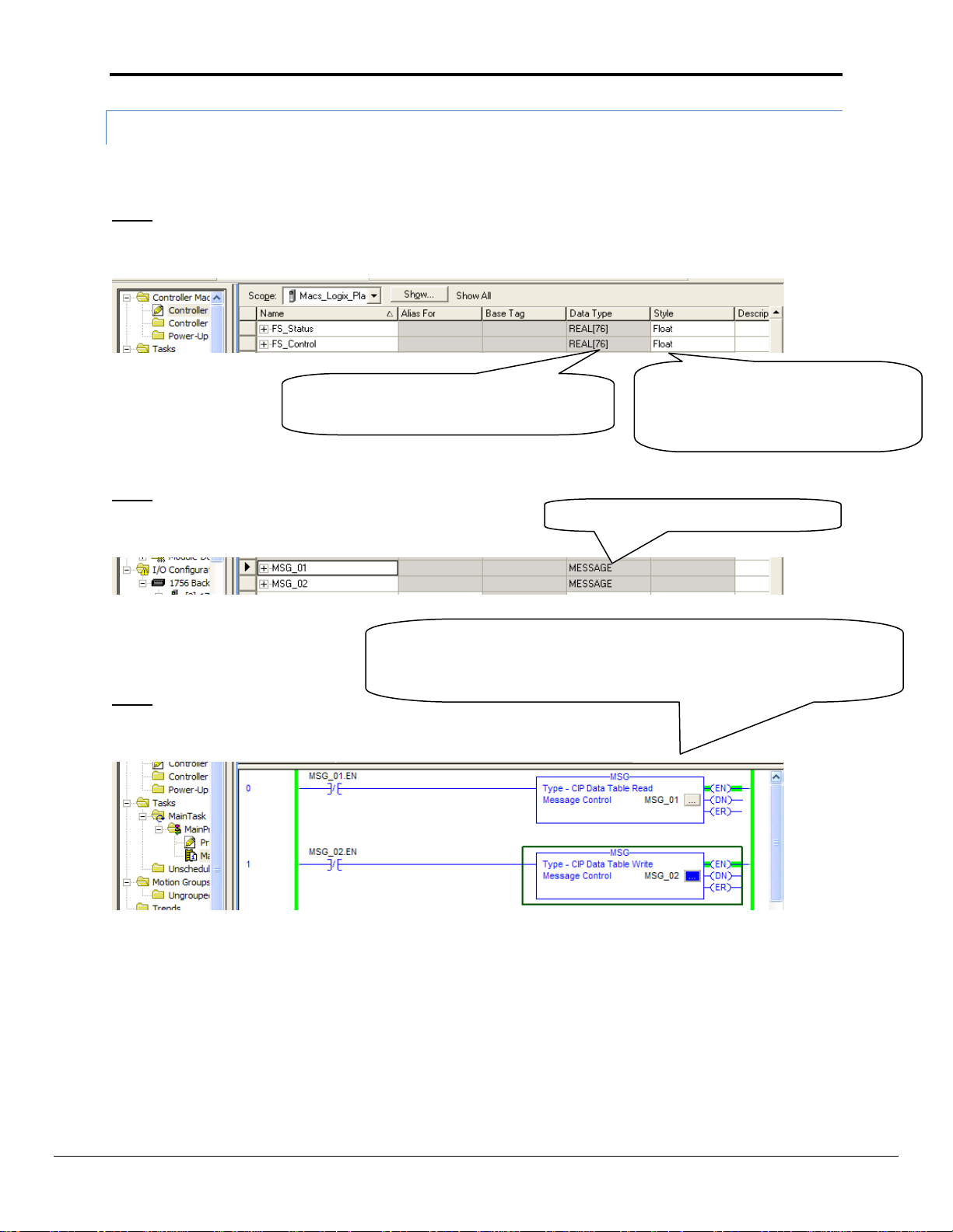
Tag Length Must be equal to or greater than
the number of points being written/read
MESSAGE Data Type must be used.
Avoid Using UDT Types. The Data will
be read but the exact placement of
the data in the Tags and Arrays will be
hard to determine
Note that this logic shown will cause the PLC to poll the FieldServer at a
very high speed. This may overload network traffic - logic that schedules
the communication at a slower rate is generally more advisable.
Appendix A.5.2. The PLC Program
The PLC program example below shows the minimum steps necessary to program communications with the
FieldServer. Depending on the real intended application, additional steps may be necessary for completeness.
Step 1
Configure Tags in the PLC for storing FieldServer read and write data:
Step 2
Configure Message Tags for storage of Message Block data:
Step 3
Write Ladder Logic to exercise a Read and Write Message Block
FieldServer Technologies 1991 Tarob Court Milpitas, California 95035 USA Web: www.fieldserver.com
Tel: (408) 262 2299 Fax: (408) 262 2269 Toll Free: (888) 509 1970 email: support@fieldserver.com
Page 20

FS-8704-14 EtherNet/IP Manual Page 20 of 30
Remote FieldServer Tag Configured in the FieldServer (see example above)
Local PLC Tag configured in the PLC Tag List (see example above)
Local PLC Tag configured in the PLC Tag List (see example above)
Remote FieldServer Tag configured in the FieldServer (see example above)
Number of points transferred from FieldServer
to PLC regardless of Tag and Array Sizes
Number of points transferred from PLC to FieldServer
regardless of Tag and Array Sizes
EIP_Card is the name of the Ethernet ENBT Card in the
ControlLogix Rack.
“2” refers to the port number on the ENBT Card.
192.168.1.75 is the IP Address of the FieldServer.
The Tag Tab requires no configuration.
Step 4
Configure the Properties for the two Message Blocks by clicking on the “…” button:
Read Message Block:
Write Message Block:
Communication Tab for both Message Blocks:
Step 5
Download the program and set the PLC to Run Mode.
FieldServer Technologies 1991 Tarob Court Milpitas, California 95035 USA Web: www.fieldserver.com
Tel: (408) 262 2299 Fax: (408) 262 2269 Toll Free: (888) 509 1970 email: support@fieldserver.com
Page 21

FS-8704-14 EtherNet/IP Manual Page 21 of 30
Appendix A.6. Configuring a FieldServer to read and write Data to and from a PLC.
This example makes use of the Data Table Read/Write method for passing data between the FieldServer and an
Allen Bradley PLC. The example shows configuration of a ControlLogix PLC, but all RockWell PLC’s that support
Ethernet IP communications and Data Table Read/Write operations in Message blocks should be able to
communicate this way. . These map descriptors will create an explicit connection to the server and will then
transfer data in the data table format. The EIP_Tag_Name field contains the tag name referenced in the server
and the EIP_Path field represents the path (through different ports) to the server. Each port jump is separated by a
space. This field generally holds a backplane / cpu slot combination. DATA_TABLE_READ and DATA_TABLE_WRITE
are the only legal values for EIP_SERVICE.
Note that this is by far the preferred method for communicating with Allen Bradley PLC’s due to it’s ease of
configuration, quantity of data that can be transferred and speed of transfer.
When the FieldServer is the active component as shown below (i.e: the FieldServer Polls the PLC and not the other
way around), then very little programming is needed in the PLC, other than the Tag Creation and setting the PLC IP
Address.
FieldServer Technologies 1991 Tarob Court Milpitas, California 95035 USA Web: www.fieldserver.com
Tel: (408) 262 2299 Fax: (408) 262 2269 Toll Free: (888) 509 1970 email: support@fieldserver.com
Page 22

FS-8704-14 EtherNet/IP Manual Page 22 of 30
// Data Arrays
//
Data_Arrays
Data_Array_Name
,Data_Format
,Data_Array_Length
DA_Read
,Float
,50
DA_Write
,Float
,50
// Client Side Connections
// Connections
Adapter
,Protocol
N1
,Ethernet/IP
// Client Side Nodes
// Nodes
Node_Name
,IP_Address
,Protocol
,Adapter
EIP_01
,192.168.1.9
,Ethernet/IP
,N1
// Client Side Map Descriptors
//
Map_Descriptors
Map_Descriptor_Name
,Scan_Interval
,Data_Array_Name
,Data_Array_Offset
,EIP_CON_TYP
,Node_Name
,Function
,EIP_SERVICE
,EIP_PATH
,EIP_TAG_NAME
,Length
PLC_TO_FIELDSERVER
,0.1
,DA_Read
,0
,EXPLICIT
,EIP_01
,Rdbc
,DATA_TABLE_READ
,1 0
,FS_Status
,20
FIELDSERVER_TO_PLC
,0.1
,DA_Write
,0
,EXPLICIT
,EIP_01
,Wrbc
,DATA_TABLE_WRITE
,1 0
,FS_Control
,20
These are the PLC Tag names that will be accessed in the PLC.
The names must match the PLC tag name exactly.
Appendix A.3 lists the paths for
specific devices
Appendix A.6.1. FieldServer Configuration File
FieldServer Technologies 1991 Tarob Court Milpitas, California 95035 USA Web: www.fieldserver.com
Tel: (408) 262 2299 Fax: (408) 262 2269 Toll Free: (888) 509 1970 email: support@fieldserver.com
Page 23
FS-8704-14 EtherNet/IP Manual Page 23 of 30
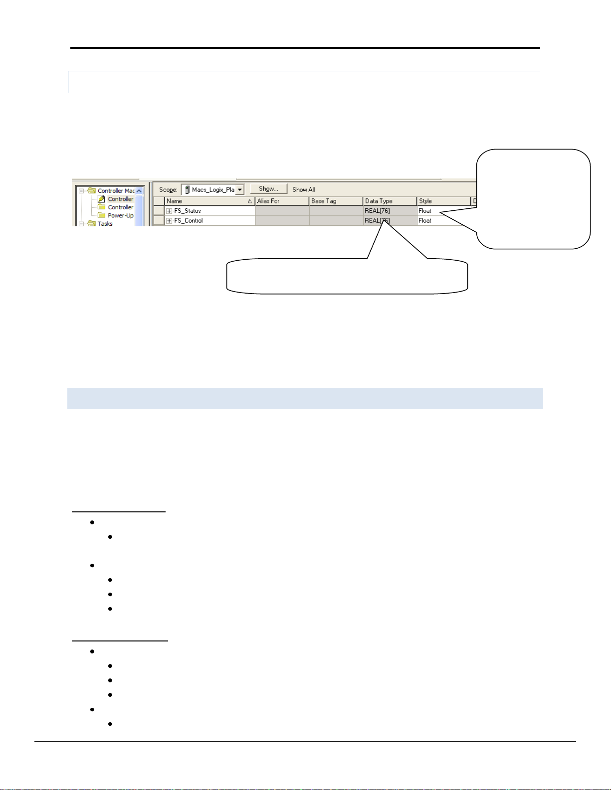
Avoid Using UDT
Types. The Data will
be read but the exact
placement of the data
in the Tags and Arrays
will be hard to
determine
Tag Length must be equal to or greater than the
number of points being written/read
Appendix A.6.2. The PLC Program
The PLC program example below shows the minimum steps necessary to program communications with the
FieldServer. Depending on the real intended application, additional steps may be necessary for completeness.
When the FieldServer is polling the PLC, all that is needed is to configure the tags being accessed:
Step 2
Note that providing dedicated (long), flat structured (not UDT) tags for communicatons interface to the FieldServer
is preferable to polling single length tags in the PLC as it allows for much more efficient communications and
reduces complexity when mapping data in the FieldServer. It is better to think of these tags as a “I/O Buffer”
Interface that the real tags in the PLC get mapped to.
Appendix A.7. Read/write structures and value of EIP_Structure_Handle :
Some devices require that a specific value be used for the EIP_Structure _Handle field while writing the structure
to them. This value may be specified in the vendor documentation. If any non-zero integer is used in a Read Map
Descriptor for EIP_Structure_Handle, the value will be updated internally. The Map Descriptor can then be
browsed to obtain this value. Other devices do not validate this field when the structure is written by the thirdparty device. A summary of the procedures to obtain this value is presented below:
FieldServer as a Client:
Read:
Use a value of 1, the driver will automatically update the field when a response is received from the
device. The Map Descriptor can then be browsed to obtain the value if required.
Write:
Use the value supplied by the vendor OR
Use the value obtained in the Read Map Descriptor above OR
Use any non-zero value if the other device doesn’t validate it.
FieldServer as a Server:
Read:
Use the value supplied by the vendor OR
Use the value obtained in the Read Map Descriptor above OR
Use any value if the other device doesn’t validate it.
Write:
Not required – use any non-zero value if the parameter is specified.
FieldServer Technologies 1991 Tarob Court Milpitas, California 95035 USA Web: www.fieldserver.com
Tel: (408) 262 2299 Fax: (408) 262 2269 Toll Free: (888) 509 1970 email: support@fieldserver.com
Page 24

FS-8704-14 EtherNet/IP Manual Page 24 of 30
// Read/write structures
Map_Descriptors
Map_Descriptor_Name
,Data_Array_Name
,Data_Array_Offset
,Function
,EIP_CON_TYP
,Node_Name
,EIP_SERVICE
,EIP_Path
,EIP_TAG_NAME
,EIP_Structure_Handle
,Length
,Scan_Interval
CMD_Struct_SINT3
,DA_STRUCT_R
,0
,Rdbc
,EXPLICIT
,EIP_01
,DATA_TABLE_READ
,1 0
,TAG_3ROOM_TEMPS
,59592
,3
,1.0s
Example: Consider a situation where a customer defines a a type in RSlogix SSS_SINT3 with 3 members of each type SINT.
SSS_SINT3
SINT room1_temp
SINT room2_temp
SINT room3_temp
Now he has his own type SSS_SINT3 and he can define tags: TAG_3ROOM_TEMPS of type SSS_SINT3
FieldServer Technologies 1991 Tarob Court Milpitas, California 95035 USA Web: www.fieldserver.com
Tel: (408) 262 2299 Fax: (408) 262 2269 Toll Free: (888) 509 1970 email: support@fieldserver.com
Page 25

FS-8704-14 EtherNet/IP Manual Page 25 of 30
FieldServer Data Type
Description (or Device Data Type)
Identity – Class Code 0x01
Attributes Supported:
One instance supported (0x01)
Attributes List:
Vendor ID
Device Type
Product Code
Device Revision
Status
Serial Number
Device Description (text)
Services Supported:
Get_Attribute_All;
Get_Attribute_Single
Message Router – Class Code
0x02
Attributes Supported:
One instance supported (0x01)
Attribute List:
Max Connections
Services Supported:
Get_Attribute_Single
Assembly – Class Code 0x04
Attributes Supported:
Class Instance Support (0x00)
Class Attributes: 0x02 (Max Instance)
Two instances supported (0x0100 and 0x0101)
Attribute List:
Member List
Not Supported
Data
Services Supported:
Get_Attribute_Single
Connection Manager – Class
Code 0x06
Forward Open Service
Forward Close Service
Register – Class Code 0x07
Attributes Supported:
Class Instance Support (0x00)
Class Attributes: 0x02 (Max Instance)
Two instances supported (0x01 and 0x02)
Attribute List:
Status Flag
Direction (read/write)
Size of Data (bits)
Services Supported:
Get_Attribute_Single
Discrete Input Point – Class Code
0x08
No visible interface currently
Discrete Output Point – Class
Code 0x09
No visible interface currently
Appendix A.8. Classes and Attributes Supported
EtherNet/IP is an object orientated protocol. The Object Oriented structure therefore allows for classes, instances,
attributes and services. The ‘data types’ listed below are to be considered as the objects supported in the
protocol. Each of these has attributes that have been supported to differing degrees.
FieldServer Technologies 1991 Tarob Court Milpitas, California 95035 USA Web: www.fieldserver.com
Tel: (408) 262 2299 Fax: (408) 262 2269 Toll Free: (888) 509 1970 email: support@fieldserver.com
Page 26

FS-8704-14 EtherNet/IP Manual Page 26 of 30
FieldServer Data Type
Description (or Device Data Type)
Analog Input Point – Class Code
0x0A
Attributes Supported:
Class Instance Support (0x00)
Class Attributes: 0x02 (Max Instance)
Two instances supported (0x01 and 0x02)
Attribute List:
Number of Attributes
Not Supported
Analog value (UINT16)
not supported
Vendor ID
Services Supported:
Get_Attribute_Single
Analog Output Point – Class Code
0x0B
Attributes Supported:
Class Instance Support (0x00)
Class Attributes: 0x02 (Max Instance)
Two instances supported (0x01 and 0x02)
Attribute List:
Number of Attributes
not supported
Analog value (UINT16)
not supported
Vendor ID
Services Supported:
Set_Attribute_Single;
Get_Attribute_Single
TCP/IP Interface Object – Class
Code 0xF5
Attributes Supported:
One instance supported (0x01)
Attribute List:
Status
Configuration Capability
Configuration Control
Physical Link Object
Interface Configuration
Host Name
Services Supported:
Get_Attribute_Single
EtherNet Link Object – Class
Code 0xF6
Attributes Supported:
One instance supported (0x01)
Attribute List:
Interface Speed
Interface Flags
Physical Address
Interface Counters
Media Counters
Services Supported:
Get_Attribute_Single
Data Table Object – Private
Object
Attributes Supported:
This object does not support instances or attributes
but uses the data table structure, and associated
tags, in Logix5000 PLC’s.
Services Supported:
CIP Read Data
FieldServer Technologies 1991 Tarob Court Milpitas, California 95035 USA Web: www.fieldserver.com
Tel: (408) 262 2299 Fax: (408) 262 2269 Toll Free: (888) 509 1970 email: support@fieldserver.com
Page 27

FS-8704-14 EtherNet/IP Manual Page 27 of 30
Err Code
Extd Err Code
Description
Action
0001
Connection Failure
0100
Connection in Use
0103
Transport not Supported
0106
Ownership conflict
0107
Connection not found
0108
Invalid connection type
0109
Invalid connection size
0110
Module not configured
0111
EPR not supported
0114
Wrong module
0115
Wrong device type
0116
Wrong revision
0118
Invalid configuration format
011A
Application out of connections
0203
Connection timeout
0204
Unconnected message timeout
0205
Unconnected send parameter error
0206
Message too large
0301
No buffer memory
0302
Bandwidth not available
0303
No screeners available
0305
Signature match
0311
Port not available
0312
Link address not available
0315
Invalid segment type
0317
Connection not scheduled
0002
Insufficient Resource
0003
Invalid value
0004
IOI syntax error
0000
Extended status out of memory
0001
Extended status out of instances
0005
0000
Extended status out of memory
0001
Extended status out of instances
0006
Insufficient packet space
0007
Connection lost
0008
Service unsupported
0009
Error in data segment or invalid attribute value
000A
Attribute list error
000B
State already exists
000C
Object model conflict
000D
Object already exists
000E
Attribute not settable
000F
Permission denied
0010
Device state conflict
Appendix A.9. Error Codes
FieldServer Technologies 1991 Tarob Court Milpitas, California 95035 USA Web: www.fieldserver.com
Tel: (408) 262 2299 Fax: (408) 262 2269 Toll Free: (888) 509 1970 email: support@fieldserver.com
Page 28

FS-8704-14 EtherNet/IP Manual Page 28 of 30
Err Code
Extd Err Code
Description
Action
0011
Reply will not fit
0012
Fragment primitive
0013
Insufficient command data
0014
Attribute not supported
0015
Too much data
001A
Bridge request too large
001B
Bridge response too large
001C
Attribute list shortage
001D
Invalid attribute list
001E
Embedded service error
001F
Connection related failure
0203
Connection timeout
0022
Invalid reply received
0025
Key segment error
0026
Invalid IOI error
0027
Inexpected attribute in list
0028
DeviceNet error - invalid member ID
0029
DeviceNet error - member not settable
00D1
Module not in run state
00FB
Message port not supported
00FC
Message unsupported data type
00FD
Message uninitialized
00FE
Message timeout
00FF
General error (see extended error codes)
2001
Excessive IOI
2002
Bad parameter value
2018
Semaphore reject
201B
Size too small
201C
Invalid size
2100
Privilege failure
2101
Invalid keyswitch position
2102
Password invalid
2103
No password issued
2104
Address out of range
2105
Address and how many out of range
2106
Data in use
2107
Type is invalid or not supported
2108
Controller in upload or download mode
2109
Attempt to change number of array dimensions
210A
Invalid symbol name
210B
Symbol does not exist
210E
Search failed
210F
Task cannot start
2110
Unable to write
2111
Unable to read
2112
Shared routine not editable
2113
Controller in faulted mode
2114
Run mode inhibited
FieldServer Technologies 1991 Tarob Court Milpitas, California 95035 USA Web: www.fieldserver.com
Tel: (408) 262 2299 Fax: (408) 262 2269 Toll Free: (888) 509 1970 email: support@fieldserver.com
Page 29

FS-8704-14 EtherNet/IP Manual Page 29 of 30
Appendix B. Troubleshooting Tips
Appendix B.1. Firmware Update Downloading
If you are trying to update firmware and continuously get failed messages it might be due to the traffic on the N 1
or N2 ports. EtherNet/IP is a high traffic protocol and once a connection is created continuous data transfer
occurs. In this situation the best way to download new firmware would be to manually disconnect the scanner or
adapter that the FieldServer is connected to.
Appendix B.2. Connection information – Allen Bradley Message Blocks
When configuring message blocks it is necessary to enter a path to the FieldServer in the communications tab. The
Path is usually made up of the installed Ethernet card, the port on the Ethernet card and the IP address of the
FieldServer
e.g. Eth_IP_Card1,2,192.168.2.41
Eth_IP_Card1 is the name given to the Ethernet Card
2 is the port on the card
The IP address is for the FieldServer
Appendix B.3. FieldServer not recognised by RSlinx
If RSlinx does not recognise the FieldServer (message “? Unrecognized Device”), load the Ethernet IP EDS file into
RSLinx. This file is available at: http://www.fieldserver.com/techsupport/utility/utility.php
Press Start|all programs|Rockwell Software|RSlinx tools|EDS Hardware Installation tool|add|register a
single file and browse to the location of the Ethernet IP EDS file.
Run RSlinx, press communication|RSwho and all EIP devices on the network should be visible.
FieldServer Technologies 1991 Tarob Court Milpitas, California 95035 USA Web: www.fieldserver.com
Tel: (408) 262 2299 Fax: (408) 262 2269 Toll Free: (888) 509 1970 email: support@fieldserver.com
Page 30

FS-8704-14 EtherNet/IP Manual Page 30 of 30
Message
Description
"EIP:#01 FYI. %d out of %d data
elements will be stored"
"MD=%s, data_type=0x%04X,
raw bytes=%d"
If the number of data elements exceeds the Map Descriptor length only the
number of data elements corresponding to the Map Descriptor will be stored.
This message will print once per Map Descriptor.
Appendix C. Error Messages
FieldServer Technologies 1991 Tarob Court Milpitas, California 95035 USA Web: www.fieldserver.com
Tel: (408) 262 2299 Fax: (408) 262 2269 Toll Free: (888) 509 1970 email: support@fieldserver.com
 Loading...