

Page 1

A Sierra Monitor Company
Driver Manual
(Supplement to the FieldServer Instruction Manual)
FS-8704-12 GE-EGD (Ethernet Global Data)
APPLICABILITY & EFFECTIVITY
Effective for all systems manufactured after May 1, 2001
Driver Version: 1.02
Document Revision: 1
Page 2

FS-8704-12_GE-EGD Manual Table of Contents
TABLE OF CONTENTS
1. GE-EGD (ETHERNET GLOBAL DATA) DESCRIPTION...................................................3
2. DRIVER SCOPE OF SUPPLY............................................................................................4
2.1. Supplied by FieldServer Technologies for this driver ...................................................4
2.2. Provided by the Supplier of 3rd Party Equipment..........................................................4
3. HARDWARE CONNECTIONS ...........................................................................................5
4. CONFIGURING THE FIELDSERVER AS A GE-EGD CLIENT..........................................6
4.1. Data Arrays...................................................................................................................6
4.2. Client Side Connection Descriptors..............................................................................7
4.3. Client Side Node Descriptors .......................................................................................7
4.4. Client Side Map Descriptors........................................................................................8
4.4.1. FieldServer Specific Map Descriptor Parameters .....................................................8
4.4.2. Driver Specific Map Descriptor Parameters..............................................................8
4.4.3. Map Descriptor Example. 1 - Map Descriptor Basics..............................................10
4.4.4. Map Descriptor Example. 2 - A Simple Consumer Map Descriptor ........................10
4.4.5. Map Descriptor Example. 3 - Multiple Consumer Map Descriptor ..........................11
5. CONFIGURING THE FIELDSERVER AS A GE-EGD SERVER......................................12
5.1. Server Side Connection Descriptors...........................................................................12
5.2. Server Side Node Descriptors....................................................................................12
5.3. Server Side Map Descriptors......................................................................................13
5.3.1. FieldServer Specific Map Descriptor Parameters ...................................................13
5.3.2. Driver Specific Map Descriptor Parameters............................................................13
5.3.3. Timing Parameters..................................................................................................14
5.3.4. Map Descriptor Example.........................................................................................15
APPENDIX A. ADVANCED TOPICS ......................................................................................16
Appendix A.1. Enable the FieldServer to read data from a 90-xx PLC.................................16
Appendix A.1.1. Use Versapro to configure/look at the EGD configuration. .....................16
5.3.5. Create a CSV file that will consume the produced data..........................................18
Appendix A.2. Data Types....................................................................................................21
APPENDIX B. ERROR MESSAGES.......................................................................................22
Appendix B.1. EGD-ii (EGD Internal Indications) .................................................................23
Appendix B.2. Driver Stats....................................................................................................24
APPENDIX C. TROUBLESHOOTING TIPS............................................................................25
Appendix C.1. ProducerID with FieldServer device as Producer .........................................25
Appendix C.2. Produced Time Stamp ..................................................................................25
Appendix C.3. Status Values................................................................................................25
FieldServer Technologies 1991 Tarob Court Milpitas, California 95035 USA Web:www.fieldserver.com
Tel: (408) 262-2299 Fax: (408) 262-9042 Toll_Free: 888-509-1970 email: support@fieldserver.com
Page 3

FS-8704-12_GE-EGD Manual Page 3 of 26
1. GE-EGD (Ethernet Global Data) Description
The GE-EGD (Ethernet Global Data) driver allows the FieldServer to transfer data to and from
devices over Ethernet using GE-EGD (Ethernet Global Data) protocol. There are two Ethernet
ports standard on the FieldServer. The FieldServer can emulate either a Server or Client.
GE Fanuc Automation and GE Drive Systems developed an Ethernet Global Data, or EGD,
exchange for PLC and computer data in 1998. EGD uses UDP or datagram messages for fast
transfer of up to 1400 bytes of data from a producer to one or more consumers. UDP
messages have much less overhead than the streaming TCP connection used for programming
or CommReq’s over SRTP Ethernet. Like Genius® broadcast input or directed control
messages, UDP messages are not acknowledged. They can be sent at short intervals.
Chances of one or more messages being dropped are small on a local area network.
As a client the FieldServer acts as an EGD consumer. As a master the FieldServer acts as an
EGD producer.
The IC697CMM742 Ethernet module supports both GE SRTP and GE EGD.
FieldServer Technologies 1991 Tarob Court Milpitas, California 95035 USA Web:www.fieldserver.com
Tel: (408) 262-2299 Fax: (408) 262-9042 Toll_Free: 888-509-1970 email: support@fieldserver.com
Page 4

FS-8704-12_GE-EGD Manual Page 4 of 26
2. Driver Scope of Supply
2.1. Supplied by FieldServer Technologies for this driver
FieldServer Technologies
PART #
FS-8915-10 UTP cable (7 foot) for Ethernet connection
FS-8704-12 Driver Manual.
Description
2.2. Provided by the Supplier of 3rd Party Equipment
EGD capable GE communication/processor module.
The IC697CMM742 modules configured with Control and IC693CPU364 and IC200CPUE05
configured with VersaPro can send and receive EGD.
FieldServer Technologies 1991 Tarob Court Milpitas, California 95035 USA Web:www.fieldserver.com
Tel: (408) 262-2299 Fax: (408) 262-9042 Toll_Free: 888-509-1970 email: support@fieldserver.com
Page 5
FS-8704-12_GE-EGD Manual Page 5 of 26
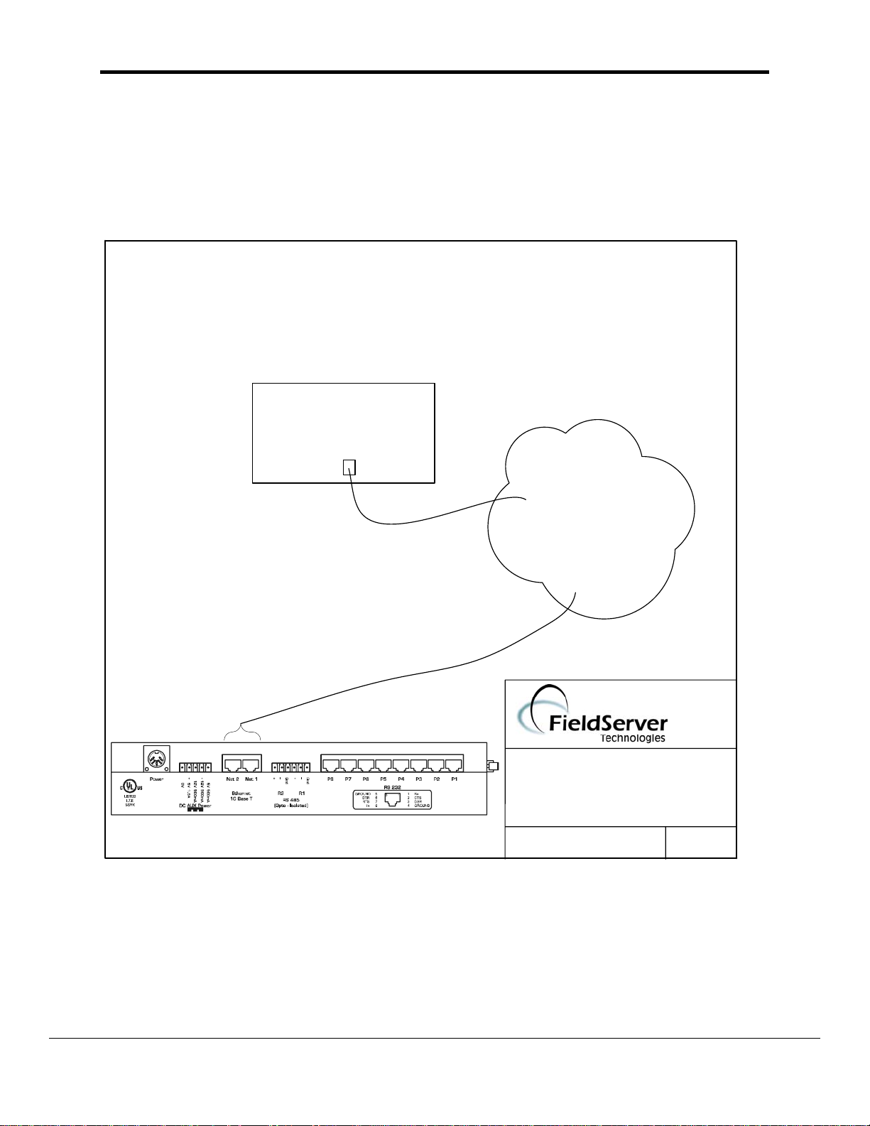
3. Hardware Connections
The FieldServer is connected to the Site Ethernet as shown below.
Configure and connect the "GE TCP/IP Ethernet Interface Type 2" according to manufacturer’s
instructions.
N7
Site Ethernet
FIELDSERVER
CONNECTION DIAGRAM
BASE NAME:
FILE NAME:
GE-EGD
(408)-262-2299
DATE: 2/4/04
BY: MF
FieldServer Technologies 1991 Tarob Court Milpitas, California 95035 USA Web:www.fieldserver.com
Tel: (408) 262-2299 Fax: (408) 262-9042 Toll_Free: 888-509-1970 email: support@fieldserver.com
Page 6
FS-8704-12_GE-EGD Manual Page 6 of 26
4. Configuring the FieldServer as a GE-EGD Client
Historically, one uses the client-server model to describe the operation of most protocols.
Recently producer-consumer model protocols have started to become more numerous. The
GE-EGD (Ethernet Global Data) is a producer-consumer model protocol. In equating the two
models it is important to regard the consumer as a passive (FieldServer) client. Other clients
typically are active and poll for new data. The consumer is a passive client in that waits to
digest new data generated by a producer.
For a detailed discussion on FieldServer configuration, please refer to the instruction manual for
the FieldServer. The information that follows describes how to expand upon the factory defaults
provided in the configuration files included with the FieldServer (See “.csv” files provided with
the FieldServer).
This section documents and describes the parameters necessary for configuring the FieldServer
to communicate with a GE-EGD Producer.
The configuration file tells the FieldServer about its interfaces, and the routing of data required.
In order to enable the FieldServer for GE-EGD communications, the driver independent
FieldServer buffers need to be declared in the “Data Arrays” section, the destination device
addresses need to be declared in the “Client Side Nodes” section, and the data required from
the servers needs to be mapped in the “Client Side Map Descriptors” section. Details on how to
do this can be found below.
Note that in the tables, * indicates an optional parameter, with the bold legal value being the
default.
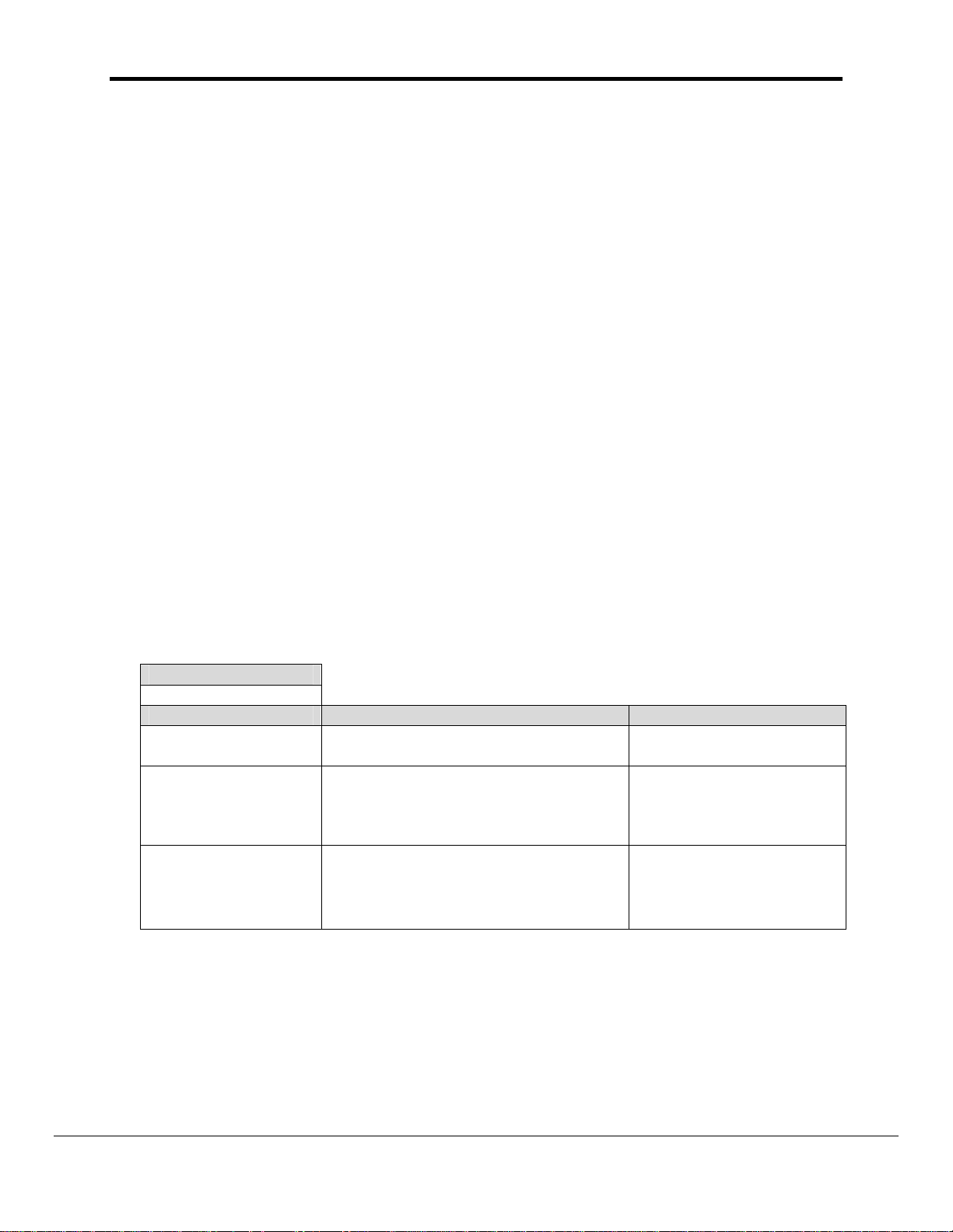
4.1. Data Arrays
Section Title
Data_Arrays
Column Title Function Legal Values
Data_Array_Name Provide name for Data Array
Data_Format
Data_Array_Length
Provide data format. Each Data Array
can only take on one format.
Number of Data Objects. Must be
larger than the data storage area
required for the data being placed in
this array.
Up to 15 alphanumeric
characters
FLOAT, BIT, UInt16,
SInt16, Packed_Bit, Byte,
Packed_Byte,
Swapped_Byte
1-10,000
FieldServer Technologies 1991 Tarob Court Milpitas, California 95035 USA Web:www.fieldserver.com
Tel: (408) 262-2299 Fax: (408) 262-9042 Toll_Free: 888-509-1970 email: support@fieldserver.com
Page 7
FS-8704-12_GE-EGD Manual Page 7 of 26
Example
// Data Arrays
Data_Arrays
Data_Array_Name, Data_Format, Data_Array_Length
DA_AI_01, UInt16, 200
DA_AO_01, UInt16, 200
DA_DI_01, Bit, 200
DA_DO_01, Bit, 200
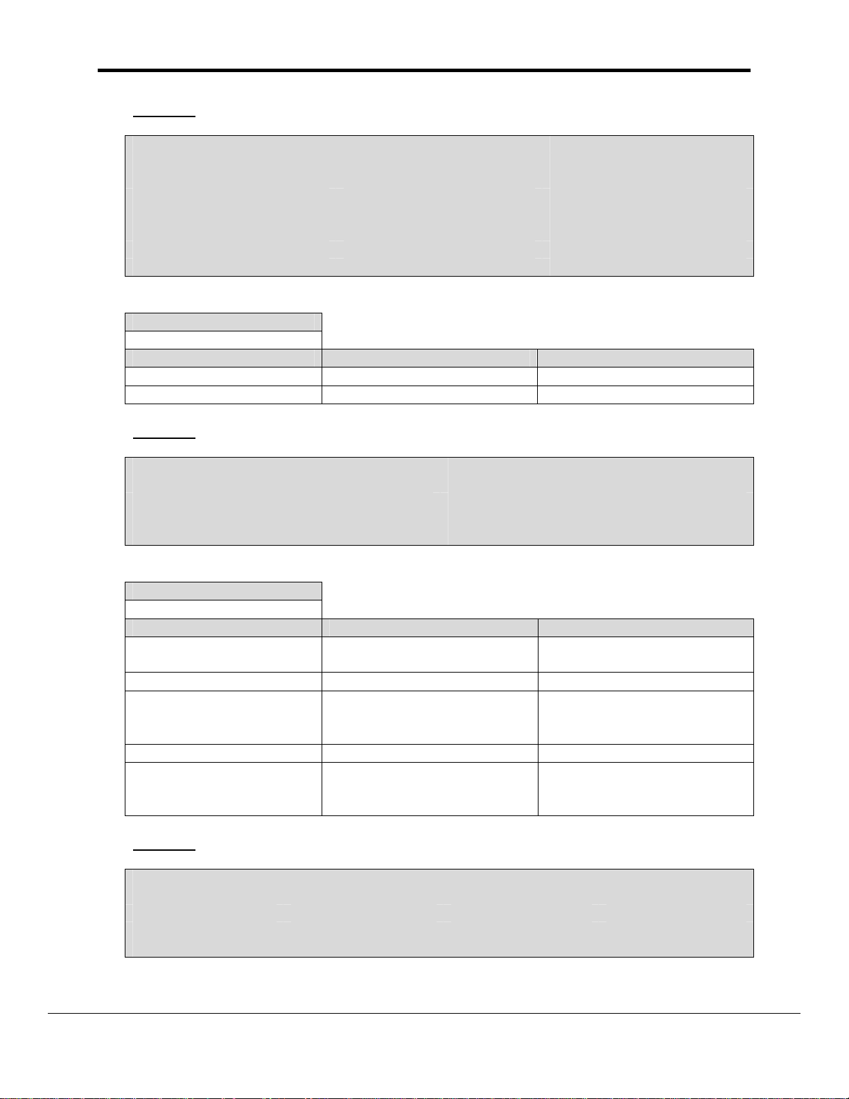
4.2. Client Side Connection Descriptors
Section Title
Adapter
Column Title Function Legal Values
Adapter Adapter Name N1,N2
Protocol Specify protocol used GE_EGD
Example
// Client Side Connections
Adapters
Adapter, Protocol
N1, GE_Egd
4.3. Client Side Node Descriptors
Section Title
Nodes
Column Title Function Legal Values
Node_Name Provide name for node
Node_ID This keyword is not required.
IP_Address
Protocol Specify protocol used GE_Egd
Adapter
Example
// Consumer (Passive Client) Side Nodes
Nodes
Node_name, IP_Address, Adapter, Protocol
node_A, 192.168.1.102, N1, ge_egd
The IP address in dot format
of the EGD-Device.
Specify which adapter
connects to the network the
EGD-device is connected to.
Up to 32 alphanumeric
characters
Nnn.nnn.nnn.nnn
Where nnn is in the range 0-
255.
N1, N2
FieldServer Technologies 1991 Tarob Court Milpitas, California 95035 USA Web:www.fieldserver.com
Tel: (408) 262-2299 Fax: (408) 262-9042 Toll_Free: 888-509-1970 email: support@fieldserver.com
Page 8

FS-8704-12_GE-EGD Manual Page 8 of 26
4.4. Client Side Map Descriptors
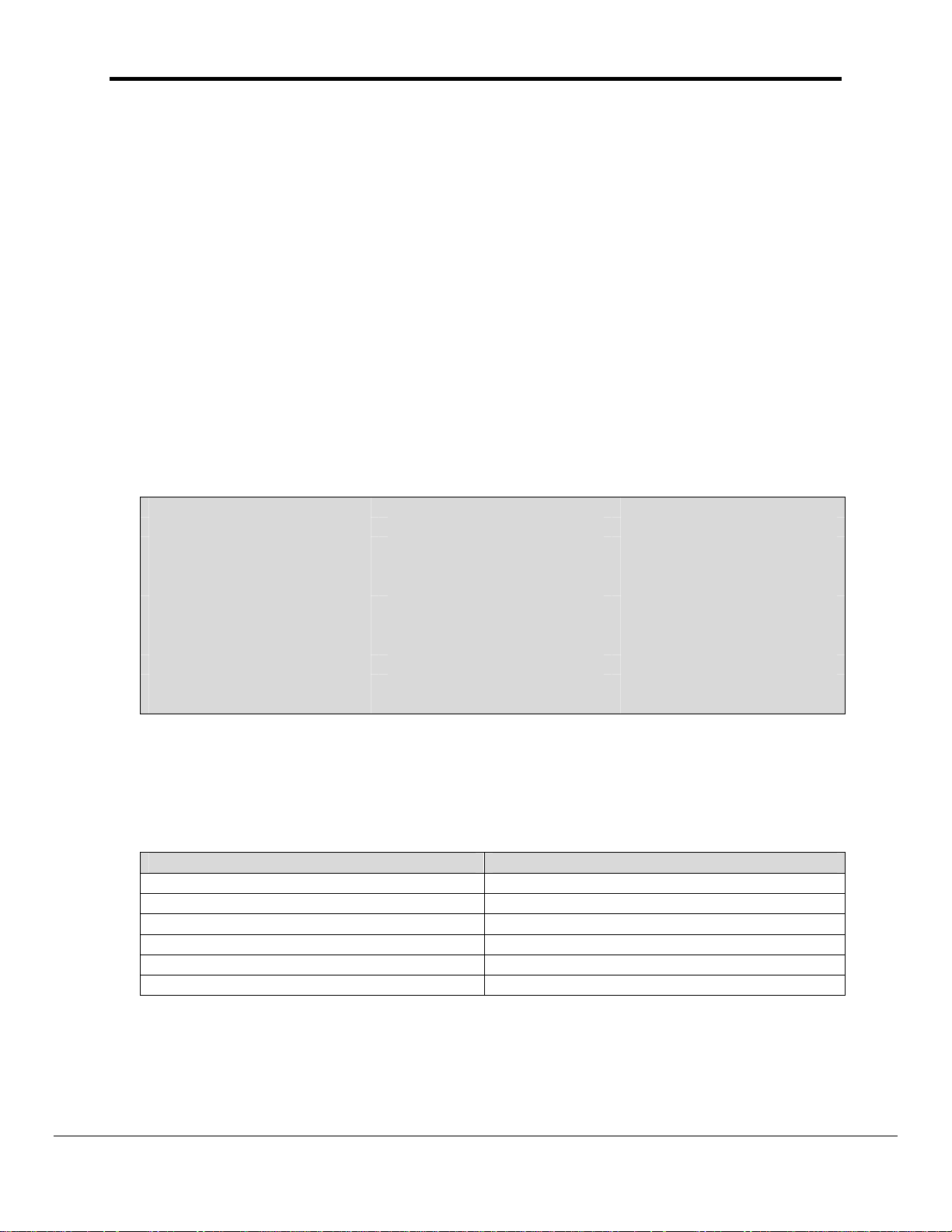
4.4.1. FieldServer Specific Map Descriptor Parameters
Column Title Function Legal Values
Up to 32 alphanumeric characters.
The Map Descriptor name can be any
name that has meaning to you and
Map_Descriptor_Name
Data_Array_Name
Data_Array_Location
Function
Name of this Map
Descriptor
Name of Data Array
where data is to be
stored in the
FieldServer
Starting location in
Data Array
Function of Client
Map Descriptor
need not be unique.
This driver recognizes a special Map
Descriptor name; "EGD-ii". It stands for
EGD Internal Indications. Its use is
more fully explained in Appendix B.1 of
this manual.
One of the Data Array names from
“Data Array” section above
0 to maximum specified in “Data Array”
section above
Passive
4.4.2. Driver Specific Map Descriptor Parameters
Column Title Function Legal Values
One of the node
Node_Name Name of Node to fetch data from
Number of points being consumed for Bit
Length
values this represents the number of bytes
(i.e. number of points divided by 8)
names specified in
“Client Node
Descriptor” above
1 - 1000
FieldServer Technologies 1991 Tarob Court Milpitas, California 95035 USA Web:www.fieldserver.com
Tel: (408) 262-2299 Fax: (408) 262-9042 Toll_Free: 888-509-1970 email: support@fieldserver.com
Page 9

FS-8704-12_GE-EGD Manual Page 9 of 26
Column Title Function Legal Values
The following keywords apply only to the GE-EGD protocol.
This identifies the GE device producing the
EGD data. Although in decimal dot format, it
is not an IP address and does not necessarily
correspond to the IP address of the GEEthernet port producing the message. It
corresponds to the producer ID configured for
ge_producerId
the CPU producing the data.
The default value is typically the same as the
IP address of the producer but the value can
be changed and it is possible for one device
Nnn.nnn.nnn.nnn
Where nnn are in the
range 0-255.
to have multiple Ethernet interfaces and
hence multiple IP addresses.
Any change to the producerID must be
matched by a similar change in the
consumer's configuration.
Used with the the producerID, to uniquely
identify a packet of EGD data. Thus, this
ge_exchangeId
driver uses these two parameters to match a
Integer values >= 1
produced data packet with one or more
passive Map Descriptors.
ge_data_type
Each produced data packet contains raw
packed data. Nothing in the message
identifies the structure or type of the incoming
data. The Driver therefore cannot
differentiate between byte, integer, real ...
numbers and requires the specification of this
keyword to unpack the data buffer.
Byte, Bit, Word,
Dword, Int , Long
Float (4 byte IEEE real
number) or Double (8
byte IEEE real
number).
If the producer has been configured to
produce data of multiple types in one data
packet then you will need multiple Map
ge_offset
Descriptors to decode them. The ge_offset is
used to point to the first byte in the data
packet to be processed by the Map
Zero, Any positive
integer
Descriptor. Typically the Map Descriptor for
the 2nd, 3rd ... Map Descriptors associated
with one data packet will be non-zero.
FieldServer Technologies 1991 Tarob Court Milpitas, California 95035 USA Web:www.fieldserver.com
Tel: (408) 262-2299 Fax: (408) 262-9042 Toll_Free: 888-509-1970 email: support@fieldserver.com
Page 10

FS-8704-12_GE-EGD Manual Page 10 of 26
y
4.4.3. Map Descriptor Example. 1 - Map Descriptor Basics
In this example the basics required for each consumer Map Descriptor are explained.
Map_Descriptor_Name, Data_Array_Name, Data_Array_Offset, Function, node_name, Length, ge_producerID, ge_exchangeID
A1, DA_AI3, 5, Passive, Node_A, 1, 0.0.0.1, 1
Data processed
by this Map
Descriptor will
be stored in this
array.
The first element
of data will be
stored in the
Data Array in
the 6th position
(Array elements
are indexed
from zero.).
When you
define Map
Descriptors to
consume EGD
data they must
be passive.
The node name
ties the Map
Descriptor to a
node which in
turn ties the Map
Descriptor to an
adapter a
nd a
protocol.
This is the number
of data elements
that will be
consumed from the
message be
processed using this
Map Descriptor.
These
parameters are
required but will
be explained in
the next
example.
4.4.4. Map Descriptor Example. 2 - A Simple Consumer Map Descriptor
Map_Descriptor_Name, Data_Array_Name, Data_Array_Offset, Function, node_name, Length, ge_producerID, ge_exchangeID, ge_Data_Type
A1, DA_AI3, 0, Passive, Node_A, 20, 0.0.0.1, 1, Int
This is the dot format ID of the
producer. It is not the IP address of the
producer's Ethernet node.
This value identifies the producing
processor.
This and the exchangeID uniquely
identif
a produced data packet.
This is a numeric value
assigned by the PLC
programmer to identify a
specific data exchange to be
received by the consuming
device (the FieldServer in this
case). It must match the ID
specified in the producer.
The data in the data packet will be treated as
16 bit (two byte) signed integers. As the
length=20 a total of 40 bytes will be processed.
The type of the Data Array should be capable
of storing signed integers in this example.
If you do not use this keyword then the driver
will process the data as bytes.
The data type is more completely explained in
section Appendix A.1
FieldServer Technologies 1991 Tarob Court Milpitas, California 95035 USA Web:www.fieldserver.com
Tel: (408) 262-2299 Fax: (408) 262-9042 Toll_Free: 888-509-1970 email: support@fieldserver.com
Page 11

FS-8704-12_GE-EGD Manual Page 11 of 26
4.4.5. Map Descriptor Example. 3 - Multiple Consumer Map Descriptor
In this example we assume that one produced data packet (produced by 0.0.0.1 and identified as exchange 1) contains different
types of data elements making up the single exchange. This is configured when configuring EGD for the producer. The
arrangement of data must correspond exactly with the configuration of the Map Descriptors used to consume the data. The following
two Map Descriptors imply that the exchange contains at least 180 bytes of data and that the first 40 bytes contain 20 word values
and that bytes 100 to 179 contain bit values. We cannot deduce what bytes 40-99 contain. Perhaps we have no interest in this
produced data.
Map_Descriptor_Name, Data_Array_Name, Data_Array_Offset, Function, node_name, Length, ge_producerID, ge_exchangeID, ge_Data_Type, ge_offset
A1, DA_AI3, 0, Passive, Node_A, 20 , 0.0.0.1 , 1, Int, 0
A2, DA_DI1, 0, Passive, Node_A, 80 , 0.0.0.1, 1, Bit, 100
The producerID and
exchangeID for
both these Map
Descriptors are
identical.
Therefore they will
both be applied to
the same
incoming data
packet.
The data types are different.
The one Map Descriptor will
be used to interpret
incoming data as integers
and the other will interpret
data as bits. These data
types must correspond to
the way the producer is
configured.
The 2nd Map
Descriptor will
process data
bytes starting at
byte 100. As the
first byte is
identified as byte
zero, byte 100 is
actually the 101st
byte in the data
part of the
message.
FieldServer Technologies 1991 Tarob Court Milpitas, California 95035 USA Web:www.fieldserver.com
Tel: (408) 262-2299 Fax: (408) 262-9042 Toll_Free: 888-509-1970 email: support@fieldserver.com
Page 12

FS-8704-12_GE-EGD Manual Page 12 of 26
5. Configuring the FieldServer as a GE-EGD Server
5.1. Server Side Connection Descriptors
Section Title
Connections
Column Title Function Legal Values
Adapter Adapter Name N1,N2
Protocol Specify protocol used GE_EGD
Example
Adapters
Adapter, Protocol
N1, GE_Egd
5.2. Server Side Node Descriptors
Section Title
Nodes
Column Title Function Legal Values
Node_Name Provide name for node
Node_ID This keyword is not required.
IP_Address
Protocol Specify protocol used GE_Egd
Adapter
Example
// Producer(Active Server) Side Nodes
Nodes
Node_name, IP_Address, Adapter, Protocol
node_A, 192.168.1.102, N1, ge_egd
The IP address in dot format
of the EGD-Device.
Specify which adapter
connects to the network the
EGD-device is connected to.
Up to 32 alphanumeric
characters
Nnn.nnn.nnn.nnn
Where nnn is in the range 0-
255.
N1, N2
FieldServer Technologies 1991 Tarob Court Milpitas, California 95035 USA Web:www.fieldserver.com
Tel: (408) 262-2299 Fax: (408) 262-9042 Toll_Free: 888-509-1970 email: support@fieldserver.com
Page 13

FS-8704-12_GE-EGD Manual Page 13 of 26
5.3. Server Side Map Descriptors
5.3.1. FieldServer Specific Map Descriptor Parameters
Column Title Function Legal Values
Up to 32 alphanumeric characters.
The Map Descriptor name can be any
name that has meaning to you and in
fact duplicate name will not produce an
Map_Descriptor_Name
Data_Array_Name
Data_Array_Location
Function
Name of this Map
Descriptor
Name of Data Array
where data is to be
stored in the
FieldServer
Starting location in
Data Array
Function of Client
Map Descriptor
error.
This driver recognizes a special Map
Descriptor name; "EGD-ii". It stands for
EGD Internal Indications. Its use is
more fully explained in section 6 of this
manual.
One of the Data Array names from
“Data Array” section above
0 to maximum specified in “Data Array”
section above
WRBC
5.3.2. Driver Specific Map Descriptor Parameters
Column Title Function Legal Values
One of the node
Node_Name Name of Node to fetch data from
Length Length of Map Descriptor 1 - 1000
Only one Map Descriptor may be
The following
keywords apply
only to the GEEGD protocol.
configured for each exchangeID. Each
produced exchange is thus limited to one
data type and to data from one Data
Array. This is different from the
configuration of consumer Map
Descriptors.
names specified in
“Producer Node
Descriptor” above
FieldServer Technologies 1991 Tarob Court Milpitas, California 95035 USA Web:www.fieldserver.com
Tel: (408) 262-2299 Fax: (408) 262-9042 Toll_Free: 888-509-1970 email: support@fieldserver.com
Page 14

FS-8704-12_GE-EGD Manual Page 14 of 26
Column Title Function Legal Values
This identifies the GE device producing
the EGD data. Although in decimal dot
format, it is not an IP address and does
not necessarily correspond to the IP
address of the GE-Ethernet port
producing the message. It corresponds
to the producer ID configured for the
ge_producerId
CPU producing the data.
The default value is typically the same as
the IP address of the producer but the
value can be changed and it is possible
Nnn.nnn.nnn.nnn
Where nnn are in the
range 0-255.
for one device to have multiple Ethernet
interfaces and hence multiple IP
addresses.
Any change to the producerID must be
matched by a similar change in the
consumer's configuration.
This and the producerID uniquely identify
a packet of EGD data. Thus, the
ge_exchangeId
consumer uses these two parameters to
update. Any change to the exchangeID
Integer values >= 1
must be matched by a similar change in
the consumer's configuration.
Each produced data packet contains raw
packed data.
Byte, Bit, Word,
Dword, Int , Long
Float (4 byte IEEE real
number) or Double (8
byte IEEE real
number).
See section Appendix
A.1 for a full list.
ge_data_type
This keyword is used to tell the driver
how to pack the data into the message.
Thus you can read from a BIT array in
the FieldServer but send the data as
words for storage in %R (register
memory) in the GE-PLC.
Any change to the data type must be
matched by a similar change in the
consumer's configuration.
ge_offset
Not required for producer Map
Descriptors.
5.3.3. Timing Parameters
Column Title Function
Scan_Interval
Rate at which data is produced. This is the equivalent of
the producer interval.
FieldServer Technologies 1991 Tarob Court Milpitas, California 95035 USA Web:www.fieldserver.com
Tel: (408) 262-2299 Fax: (408) 262-9042 Toll_Free: 888-509-1970 email: support@fieldserver.com
Legal
Values
>0.1s
Page 15

FS-8704-12_GE-EGD Manual Page 15 of 26
5.3.4. Map Descriptor Example.
Map_Descriptor_Name, Data_Array_Name, Data_Array_Offset, Function, node_name, Length, Scan_Interval, ge_producerID, ge_exchangeID, ge_data_type
A1, DA_AI3, 0, Wrbc, Node_A, 100 5.0s , 0.0.0.1, 1, %R
The consumer
Only a wrbc can be
used to produce data.
The other write
functions are not
periodic.
Consider this as
the producer
interval.
must be
configured to have
the same
producerID and
exchangeID.
These two fields
are the only way it
has of
differentiating one
set of produced
data from another.
Defines how data is
packed into the data part
of the message.
In this example data will
be packed words
(unsigned 16 bit integers)
suitable for storage in
register memory in the GE
PLC's.
Section Appendix A.1
contains a full list.
FieldServer Technologies 1991 Tarob Court Milpitas, California 95035 USA Web:www.fieldserver.com
Tel: (408) 262-2299 Fax: (408) 262-9042 Toll_Free: 888-509-1970 email: support@fieldserver.com
Page 16

FS-8704-12_GE-EGD Manual Page 16 of 26
Appendix A. Advanced Topics
Appendix A.1. Enable the FieldServer to read data from a 90-xx PLC.
Appendix A.1.1. Use Versapro to configure/look at the EGD
configuration.
Produced data must be produced for a specific consumer. Thus you must create a new
exchange in the PLC that will produce data for the FieldServer. (Specific consumer
means specific IP address).
Since the EGD data packet is not structured, the FieldServer cannot decode the data
ranges without the Map Descriptors. It is therefore important that the data ranges in the
produced exchange correspond to the Map Descriptors in the CSV file.
• Go online.
• View Menu, Hardware Configuration. (Launches HWC program).
• HWC. Edit. Rack Operations. EGD Configuration.
• Add an exchange. Set the CONS ADDRESS equal to the IP address of the
FieldServer.
FieldServer Technologies 1991 Tarob Court Milpitas, California 95035 USA Web:www.fieldserver.com
Tel: (408) 262-2299 Fax: (408) 262-9042 Toll_Free: 888-509-1970 email: support@fieldserver.com
Page 17

FS-8704-12_GE-EGD Manual Page 17 of 26
This is the producerID.
It may be the same as the IP address
of the adapter but this is not always
the case.
• Note the Local Producer address. Typically it will be the same as the IP of the
closest GE Ethernet port. You can override this.
• Add Ranges. Record the offset and reference for each data range in the exchange.
• Save your work.
• Close HWC.
• Stop the processor.
• Store the Hardware settings to the PLC
• Put the processor back in run mode (must be running to produce.)
A second screen image shows that this exchange actually has an additional range at
offset 8.
FieldServer Technologies 1991 Tarob Court Milpitas, California 95035 USA Web:www.fieldserver.com
Tel: (408) 262-2299 Fax: (408) 262-9042 Toll_Free: 888-509-1970 email: support@fieldserver.com
Page 18

FS-8704-12_GE-EGD Manual Page 18 of 26
You will need this
adapter’s IP
address. It will be
used as the node IP
address in the CSV
5.3.5. Create a CSV file that will consume the produced data.
An example is shown on the following page.
FieldServer Technologies 1991 Tarob Court Milpitas, California 95035 USA Web:www.fieldserver.com
Tel: (408) 262-2299 Fax: (408) 262-9042 Toll_Free: 888-509-1970 email: support@fieldserver.com
Page 19

FS-8704-12_GE-EGD Manual Page 19 of 26
Adapters
Adapter, protocol
N1, ge_egd
Nodes
Node_name, IP_Address, Adapter, Protocol
PLC90-30, 216.232.242.3, N1, ge_egd
Nodes
Node_name, Protocol
null_node, ge_egd
This is the IP address of the producing port. You can
obtain this by using the Versapro HWC program and
double clicking on the Module with the adapter shown in
the EGD configuration. (Fred, in this example) Now look
for the Ethernet port address.
Data_Arrays
Data_Array_Name, Data_Format, Data_Array_Length
DA_AO_01, Float, 200
DA_AI_00 , BYTE , 100
DA_AI_01 , BIT , 100
DA_AI_02 , UINT16 ,, 100
DA_AI_03 , UINT32, 100
DA_AI_04 , SINT16, 100
DA_AI_05 , SINT32, 100
DA_AI_06 , FLOAT, 100
DA_AI_07 , FLOAT, 100
EGD_DIAG , UINT32, 100
EGD_STATS, UINT32, 100
Map_Descriptors
Map_Descriptor_Name, Data_Array_Name, Node_name
egd-ii , EGD_DIAG , null_node
egd-stats , EGD_STATS , null_node
FieldServer Technologies 1991 Tarob Court Milpitas, California 95035 USA Web:www.fieldserver.com
Tel: (408) 262-2299 Fax: (408) 262-9042 Toll_Free: 888-509-1970 email: support@fieldserver.com
Page 20

FS-8704-12_GE-EGD Manual Page 20 of 26
Map_Descriptors
Map_Descriptor_Name, Data_Array_Name, Data_Array_Offset, Function, node_name, Length, ge_producerId, ge_exchangeId, ge_data_type, ge_offset
Q1, DATA_Q, 0 Passive, PLC90-30, 1, 1.2.3.4, 1, %q, 0
R1, DATA_R, 0 Passive, PLC90-30, 1, 1.2.3.4, 1, %r, 1
I1, DATA_R, 0 Passive, PLC90-30, 2, 1.2.3.4, 1, %u, 3
R2, DATA_R, 1 Passive, PLC90-30, 1, 1.2.3.4, 1, %r, 5
I2, DATA_R, 2 Passive, PLC90-30, 1, 1.2.3.4, 1, %i, 7
Q2, DATA_R, 1 Passive, PLC90-30, 1, 1.2.3.4, 1, %q, 8
Read the section on data types to
see how many items are being
transmitted. Note that the %Q, %I
references are actually byte
references and not bit references as
they are always produced in
multiples of 8 and are always byte
aligned.
Must correspond to
the ‘Local Producer’ in
the EGD configuration.
Is not necessarily the
IP address of the
producer port.
These offsets must
correspond to the offsets
in the EGD configuration.
These data types must
correspond to the
references in the EGD
range configuration.
FieldServer Technologies 1991 Tarob Court Milpitas, California 95035 USA Web:www.fieldserver.com
Tel: (408) 262-2299 Fax: (408) 262-9042 Toll_Free: 888-509-1970 email: support@fieldserver.com
Page 21

FS-8704-12_GE-EGD Manual Page 21 of 26
Appendix A.2. Data Types
Each produced data packet contains up to 1400 bytes of unstructured data. The
specification of the ge_data_type in the Map Descriptor tells the driver how to interpret these
raw data bytes.
The minimum data unit processed is a byte. This is the case even when the data type is
specified as bit. This is because EGD producers cannot produce a single bit. When bits are
produced the producer determines the closes byte boundary and sends a minimum of 8 bits.
The following data types are recognized by the driver
Byte
Bit (translated as 8bits aligned with a byte boundary)
Word (unsigned 16bit integer)
Dword (unsigned 32bit integer)
Int (signed 16bit integer)
Long (signed 32bit integer)
Float (translated as an IEEE 4 byte real number)
Double (translated as an IEEE 8 byte real number)
The following GE Specific data types are also recognized.
Type Description P-ProducerC-Consumer
%R Register memory in word mode P/C
%AI Analog input memory in word mode P/C
%AQ Analog output memory in word mode P/C
%I Discrete input memory in byte mode P/C
%Q Discrete output memory in byte mode P/C
%T Discrete temporary memory in byte mode P/C
%M Discrete momentary memory in byte mode P/C
%SA Discrete system memory group A in byte mode P/C
%SB Discrete system memory group B in byte mode P/C
%SC Discrete system me mory group C in byte mode P/C
%S Discrete system memory in byte mode P
%G Discrete global data table in byte mode P/C
If you use the RUI editor and view the Map Descriptors online it may appear that the driver
changed the data type but in fact all that it has done is changed the display to a synonym.
FieldServer Technologies 1991 Tarob Court Milpitas, California 95035 USA Web:www.fieldserver.com
Tel: (408) 262-2299 Fax: (408) 262-9042 Toll_Free: 888-509-1970 email: support@fieldserver.com
Page 22

FS-8704-12_GE-EGD Manual Page 22 of 26
Appendix B. Error Messages
Multiple protocol drivers may exist on a FieldServer. Each driver may produce its own error
messages and the FieldServer itself may produce error messages.
Message Action
EGD:#1 Error. Can’t init UDP.
EGD:#2 Error. Can’t get a
socket.
EGD:#3 Error. Protocol does
not support active polling.
Change function for
mapDesc=<%s>
EGD:#4 Error. Producer ID
required for mapDesc=<%s>
EGD:#5 Error. Exchange ID
required for mapDesc=<%s>
EGD:#6 FYI. No data type
specified. Defaulted to <Byte>
EGD:#7 FYI. Data type not
recognized. Defaulted to
<Byte> for mapDesc=<%s>
EGD:#8 Error. Don't know GE
Data Type(%d) for
mapDesc=<%s>
EGD:#9 Error. Incoming data
from ip=<%s>
producerID=<%s>
exchangeID=(%d) is being
abandoned.
EGD:#10 Error. Don't know GE
Data Type (%d) for
mapDesc=<%s>
EGD:#11 FYI. You could have
used a mapDesc called <egdii> to expose diagnostic info.
EGD:#12 Invalid IP. Too many
characters.
EGD:#13 Invalid IP <%s> Insufficient points in the IP address. 1
EGD:#14 Error. The mapDesc
called <egd-stats> is too short
EGD:#15 FYI. You could have
used a mapDesc called <egdstats> to expose diagnostic
info.
This is a fatal error. The FieldServer needs to be re-initialized
or you need technical support from FieldServer Technologies.
The rdbc/rdb/rdbx functions are not supported by this protocol.
The device you wish to poll must be configured to 'produce' its
data and this driver will 'consume' the data using passive Map
Descriptors.
Each Map Descriptor requires a producerID.
Each Map Descriptor requires an exchangeID.
This is a warning only. You can eliminate the warning by
editing the CSV file.
An illegal data type has been used.
1
1
1
1
1
An EGD producer has sent a data packet to the FieldServer
but the driver cannot find a passive Map Descriptor to use to
process and store the incoming data. It’s possible that the
producer has been incorrectly configured and that the packet
was not intended for the FieldServer. Alternatively, make a
new Map Descriptor which will handle this data.
1
An illegal data type has been used.
This message requires no action, but refer to Appendix B.1 of
this manual to see whether you will benefit from exposing
some driver internal diagnostic data.
1
IP address is more than 15 characters in length.
Increase the data length parameter for this Map Descriptor
Make sure the Data Array is long enough too.
Refer to Appendix B.10 \r \h |Appendix B.1} for more
information.
1
Edit the CSV file, download to the FieldServer and restart the FieldServer for the changes to take effect.
FieldServer Technologies 1991 Tarob Court Milpitas, California 95035 USA Web:www.fieldserver.com
Tel: (408) 262-2299 Fax: (408) 262-9042 Toll_Free: 888-509-1970 email: support@fieldserver.com
Page 23

FS-8704-12_GE-EGD Manual Page 23 of 26
Appendix B.1. EGD-ii (EGD Internal Indications)
This driver can expose data from the most recently consumed message and some
additional diagnostic information.
A special Map Descriptor is required. The driver recognizes the Map Descriptor by its name
which must be "EGD-ii" which stands for EGD Internal Indications.
The following example shows how this special Map Descriptor can be configured.
Nodes
Node_name, Protocol
null_node, ge_egd
Data_Arrays
Data_Array_Name, Data_Format, Data_Array_Length
EGD_DIAG, UINT32, 100
Map_Descriptors
Map_Descriptor_Name, Data_Array_Name, Node_name
egd-ii, EGD_DIAG, null_node
When the driver sees this Map Descriptor it uses the Data Array EGD_DIAG to store driver
specific data. Only one of these Map Descriptors may be specified per FieldServer.
The driver stores the following data.
Array
Element
0-31
32 PDUTypeVersion
33 RequestID
34 ProducerID2
35 ExchangeID
36 TimeStampSec
37 TimeStampNanoSec
38 Status3
39 ConfigSignature
40 Reserved
41 Source IP Address
Contents
The first 32 bytes of the most recently received UDP packet received on
port 0x4746 (The GE EGD port).
1
2
As a UINT32. Not in dot format
3
Read section 4.4 of GE-Fanuc document GFK-1541 for more information.
FieldServer Technologies 1991 Tarob Court Milpitas, California 95035 USA Web:www.fieldserver.com
Tel: (408) 262-2299 Fax: (408) 262-9042 Toll_Free: 888-509-1970 email: support@fieldserver.com
Page 24
FS-8704-12_GE-EGD Manual Page 24 of 26
Appendix B.2. Driver Stats
EGD producers produce data messages for slave devices to consume. The type and
frequency of the messages depends on the producer configuration.
The driver counts all incoming messages of interest as the PLC_READ_MSG_RECD
statistic. Other legal messages which do not contain the data this driver is interested in are
discarded and are counted as the MSG_IGNORED statistic.
The PLC_READ_MSG_RECD statistic is incremented once by each Map Descriptor which
extracts data from an incoming message. Thus, one incoming message and three
associated Map Descriptors would cause the statistic to increase by three (when viewed
from the connection's point of view.)
This driver can expose some driver statistics by writing data to a Data Array. A special Map
Descriptor is required. The driver recognizes the Map Descriptor by its name which must be
"EGD-stats”.
The following example shows how this special Map Descriptor can be configured.
Nodes
Node_name, Protocol
null_node, ge_egd
Data_Arrays
Data_Array_Name, Data_Format, Data_Array_Length
EGD_STATS, UINT32, 100
Map_Descriptors
Map_Descriptor_Name, Data_Array_Name, Node_name
egd-stats, EGD_STATS, null_node
When the driver sees this Map Descriptor it uses the Data Array EGD_STATS (in this
example) to store driver specific statistics. Only one of these Map Descriptors may be
specified per FieldServer.
The driver stores the following data.
Array Element Contents
0 Messages Produced
1 Bytes Produces
2 Messages Received
3 Bytes Received
4 Messages Consumed
5 Messages Ignored
FieldServer Technologies 1991 Tarob Court Milpitas, California 95035 USA Web:www.fieldserver.com
Tel: (408) 262-2299 Fax: (408) 262-9042 Toll_Free: 888-509-1970 email: support@fieldserver.com
Page 25

FS-8704-12_GE-EGD Manual Page 25 of 26
Appendix C. Troubleshooting Tips
Appendix C.1. ProducerID with FieldServer device as Producer
During testing it has been observed that a 90-30 PLC required that the ge_ProducerID
parameter was set to the same value as the IP Address of the FieldServer.
Appendix C.2. Produced Time Stamp
The GE-EGD (Ethernet Global Data) driver always set the timestamp of produced data to
the time of the Field Server Device. The nanoseconds portion of the time stamp is always
set to zero.
Appendix C.3. Status Values
The status of the EGD Exchange may be monitored in the GE PLC. The status value is well
documented in GFK-1541 Chapter 4.4. During testing, using the Field Server device as a
producer and the GE Device as a consumer the following status values were observed.
0 -> The exchange had never been consumed
1 -> Normal
4 -> Length of produced and consumed exchange not equal - Different messages with the
same exchange ID.
6. -> Timeout.
FieldServer Technologies 1991 Tarob Court Milpitas, California 95035 USA Web:www.fieldserver.com
Tel: (408) 262-2299 Fax: (408) 262-9042 Toll_Free: 888-509-1970 email: support@fieldserver.com
Page 26

FS-8704-12_GE-EGD Manual Page 26 of 26
THIS PAGE INTENTIONALLY LEFT BLANK
FieldServer Technologies 1991 Tarob Court Milpitas, California 95035 USA Web:www.fieldserver.com
Tel: (408) 262-2299 Fax: (408) 262-9042 Toll_Free: 888-509-1970 email: support@fieldserver.com
 Loading...