

Page 1

Driver Version:
1.05
Document Revision:
6
APPLICABILITY & EFFECTIVITY
Effective for all systems manufactured after November 2011
Driver Manual
(Supplement to the FieldServer Instruction Manual)
FS-8700-80 McQuay MicroTech® Open Protocol™
A Sierra Monitor Company
Page 2

McQuay Micro Tech Open Protocol Driver Manual Table of Contents
TABLE OF CONTENTS
1 McQuay Micro Tech Open Protocol Description ............................................................................................. 4
1.1 MicroTech Unit and System Controllers ........................................................................................................ 4
1.1.1 McQuay Equipment Types recognized by the driver. ............................................................................. 4
1.1.2 McQuay equipment not currently recongnized by the driver: ............................................................... 4
1.1.3 McQuay MicroTech network products used in conjunction with the driver: ......................................... 5
1.1.4 About MicroTech Network Architecture ................................................................................................ 6
1.2 Applying a FieldServer gateway to different MicroTech situations ............................................................... 6
1.2.1 Single standalone MicroTech 200 Series unit controller ........................................................................ 6
1.2.2 Multiple standalone MicroTech 200 Series unit controllers ................................................................... 7
1.2.3 Multiple standalone MicroTech “non-200 Series” unit controllers ........................................................ 7
1.2.4 Existing MicroTech network (Custom MicroTech Monitor software, NMP Panel, etc) .......................... 7
1.2.5 Existing MicroTech Open Protocol network ........................................................................................... 9
1.2.6 Replacing a BACdrop Gateway panel .................................................................................................... 9
1.3 MicroTech Communication Port Configuration ........................................................................................... 11
1.4 Reference Documents ................................................................................................................................. 12
2 Driver Features ............................................................................................................................................ 13
3 Driver Scope of Supply ................................................................................................................................. 13
3.1 Supplied by FieldServer Technologies for this driver ................................................................................... 13
3.2 Provided by Supplier of 3rd Party Equipment............................................................................................... 13
4 Hardware Connections ................................................................................................................................. 14
5 Data Array Parameters ................................................................................................................................. 15
6 Configuring the FieldServer as a McQuay Micro Tech Open Protocol Client ................................................. 16
6.1 Client Side Connection Parameters ............................................................................................................. 16
6.2 Client Side Node Parameters ....................................................................................................................... 17
6.3 Client Side Map Descriptors......................................................................................................................... 18
6.3.1 FieldServer Related Map Descriptor Parameters ................................................................................. 18
6.3.2 Driver Related Map Descriptor Parameters ......................................................................................... 18
6.3.3 Timing Parameters ............................................................................................................................... 18
6.3.4 Map Descriptor Example 1 – Read Everything. .................................................................................... 19
6.3.5 Map Descriptor Example 2 – Read a particular Data Field. ................................................................. 19
6.3.6 Map Descriptor Example 3 – Write. ..................................................................................................... 20
7 Configuring the FieldServer as a McQuay Micro Tech Open Protocol Server ................................................ 21
7.1 Server Side Connection Paramaters ............................................................................................................ 21
7.2 Server Side Node Parameters ...................................................................................................................... 22
7.3 Server Side Map Descriptors........................................................................................................................ 22
7.3.1 FieldServer Specific Map Descriptor Parameters ................................................................................. 22
7.3.2 Driver Specific Map Descriptor Parameters ......................................................................................... 23
7.3.3 Timing Parameters ............................................................................................................................... 23
7.3.4 Map Descriptor Example – Strategy 1. ................................................................................................ 24
7.3.5 Map Descriptor Example – Strategy 2. ................................................................................................ 24
Appendix A. Useful Features ................................................................................................................................ 25
Appendix A.1. Scaling .............................................................................................................................................. 25
Appendix A.1.1. User Scaling: ........................................................................................................................... 25
FieldServer Technologies 1991 Tarob Court Milpitas, California 95035 USA Web: www.fieldserver.com
Tel: (408) 262 2299 Fax: (408) 262 2269 Toll Free: (888) 509 1970 email: support@fieldserver.com
Page 3

McQuay Micro Tech Open Protocol Driver Manual Table of Contents
Appendix A.1.2. Device Scaling: ....................................................................................................................... 25
Appendix A.2. Direct Addressing ............................................................................................................................. 26
Appendix A.3. Direct Addressing Example 1– Reading direct address. ................................................................... 27
Appendix A.4. Direct Addressing Example 2 – Controlling Bytes per Field – Reading ............................................. 27
Appendix A.5. Advanced Map Descriptor Example 3 – Controlling Bytes per Field – Writing ................................ 28
Appendix B. Troubleshooting ............................................................................................................................... 29
Appendix B.1. Connection Problems ....................................................................................................................... 29
Appendix B.2. Negative Acknowledgement - NAK .................................................................................................. 29
Appendix B.3. Node ID problems............................................................................................................................. 29
Appendix B.4. Server Side Configuration – Consecutive Addresses ........................................................................ 30
Appendix B.5. Configuring the OPM to enable communication between the FieldServer and McQuay devices ... 30
Appendix B.5.1. Configuring multiple McQuay devices to communicate to a FieldServer without an OPM:... 30
Appendix C. Reference ......................................................................................................................................... 32
Appendix C.1. Error Messages ................................................................................................................................. 32
Appendix C.2. Statistics ........................................................................................................................................... 34
Appendix C.3. McQuay Equipment Types recognized by the driver. ...................................................................... 35
Appendix C.4. Device Scaling Method ..................................................................................................................... 35
Appendix C.5. Data Field Name Tables .................................................................................................................... 35
Appendix C.5.1. Equipment Type: 200CFC 200 Series Centrifugal Chiller ......................................................... 35
Appendix C.5.2. Equipment Type: 050RPC Reciprocating Chiller ..................................................................... 37
Appendix C.5.3. Equipment Type: 100CFC 100 Series Centrifugal Chiller ......................................................... 38
Appendix C.5.4. Equipment Type : 001ASC Air Cooled Screw Chiller ................................................................ 40
Appendix C.5.5. Equipment Type : Self-Contained Units (SCUs) ....................................................................... 41
FieldServer Technologies 1991 Tarob Court Milpitas, California 95035 USA Web: www.fieldserver.com
Tel: (408) 262 2299 Fax: (408) 262 2269 Toll Free: (888) 509 1970 email: support@fieldserver.com
Page 4
McQuay Micro Tech Open Protocol Driver Manual Page 4 of 43
Code
Description
200CFC
200 Series Centrifugal Chiller
100CFC
100 Series Centrifugal Chiller
001ASC
Air Cooled Screw Chiller – V2.2 Single Compressor Only
000SCU
Self Contained Unit
0050RPC
Reciprocating Chiller
Rooftop Unit
Water Cooled Screw Chiller
Code
Description
Global Scroll chiller
Unit Ventilator
Water Source Heat Pump (WSHP)
MicroTech 2000 WSHP (through MCG (MicroTech Communications Gateway panel)
1 MCQUAY MICRO TECH OPEN PROTOCOL DESCRIPTION
This document describes the FieldServer driver used to transfer data between a FieldServer and MicroTech® unit
and/or network of controllers manufactured by McQuay International. Transfers are done using the controller's
Data Terminal Communications Protocol. In this document the protocol is referred to as the McQuay MicroTech®
Open Protocol. MicroTech controls are legacy products that may require the use of a FieldServer device in order to
support existing applications in need of unit or network controller replacements and/or integration into a Building
Automation System (BAS).
1.1 MicroTech Unit and Syst em Controllers
McQuay International has provided BAS manufacturers licensed access to stand-alone MicroTech unit controllers.
The network access, which is called Open Protocol™, allows a BAS to monitor status and change limited control
parameters in McQuay International HVAC equipment. Monitoring and controlling MicroTech unit controllers may
have required the use of a MicroTech system panel, depending on the unit type, number of units and other
network requirements. There are multiple combinations of MicroTech unit controllers and/or system panels (i.e.
Open Protocol networks) that could use a FieldServer device. FieldServer-supported devices, McQuay Open
Protocol controller descriptions, and network architecture diagrams are all described in the following section.
The McQuay MicroTech® Open Protocol driver allows the FieldServer to transfer data to and from devices over
either RS-232 or RS-485 using McQuay MicroTech® Open Protocol. The FieldServer can emulate either a Server or
Client.
1.1.1 McQuay Equipm ent Types recogn ized by the driv er.
1.1.2 McQuay equipm ent not currently reco ngnized by the driver:
FieldServer Technologies 1991 Tarob Court Milpitas, California 95035 USA Web: www.fieldserver.com
Tel: (408) 262 2299 Fax: (408) 262 2269 Toll Free: (888) 509 1970 email: support@fieldserver.com
Page 5
McQuay Micro Tech Open Protocol Driver Manual Page 5 of 43
CB
PS
SBC
J1 connector
RJ-45
J22
L2
L1
GRD
“Etherne t” po rt
“Netwo rk” port
“PC” por t
Flash memory chip
Ethernet status LEDs
Speaker
5 Vdc power in
1.1.3 McQuay MicroTech network products us ed in conjunction wit h the driver:
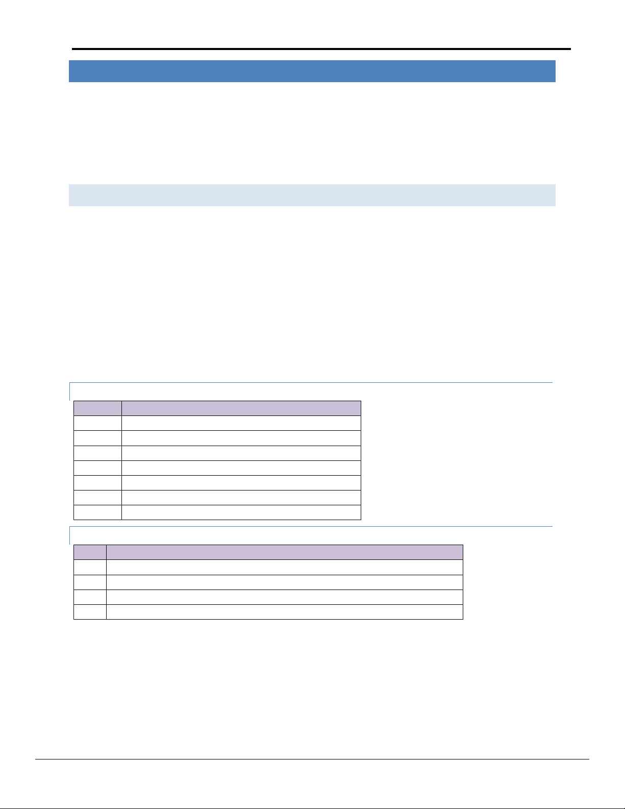
1.1.3.1 MicroTech BACdrop™ panel
The MicroTech BACdrop gateway integrates a MicroTech network into a BACnet™ building automation system
(BAS) facilitating monitoring and control of McQuay International equipment from the BAS. The gateway
translates between BACnet objects on an Ethernet® network and McQuay memory locations on a proprietary
MicroTech network.
The BACdrop gateway is a passive device. It receives, translates, and re-transmits messages including both data
and control signals from one network to the other network in either direction but does not perform any
supervisory control for the various MicroTech controllers connected to it. Figure 1 shows the important features
of the BACdrop panel.
Figure 1. BACdrop Panel
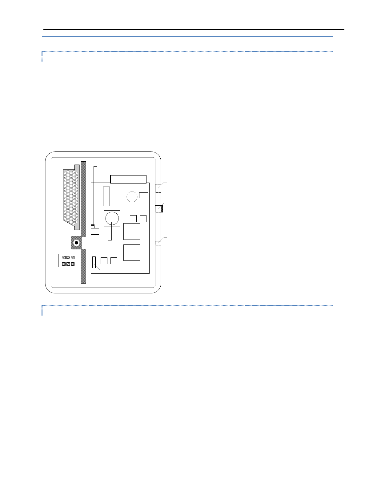
1.1.3.2 OPM – Open Protocol Master Panel
The OPM Panel is used when two or more MicroTech controllers need to be interfaced with a BAS by means of a
single-point connection. The OPM acts as a passive communications link between MicroTech controllers and the
BAS and does not perform any supervisory control for the various MicroTech controllers connected to it. When an
OPM is used, all supervisory control (scheduling, overrides, chiller sequencing) is handled by the BAS. The
maximum number of unit controllers per OPM depends on the BAS. For example, the OPM Panel could combine a
McQuay centrifugal chiller, a McQuay applied rooftop unit, and several unit ventilators into a network that a BAS
could connect to with a single cable. Figure 2 shows the important features of the OPM panel.
FieldServer Technologies 1991 Tarob Court Milpitas, California 95035 USA Web: www.fieldserver.com
Tel: (408) 262 2299 Fax: (408) 262 2269 Toll Free: (888) 509 1970 email: support@fieldserver.com
Page 6
McQuay Micro Tech Open Protocol Driver Manual Page 6 of 43
Port A
Port B
HI
LO
F1
L1
Port A Select
1 2 3
3
21
Hex
switches
Communication
ports
Red status
LED
Green
status LED
Figure 2. OPM Panel
1.1.3.3 Alternatives to the OPM Panel
The following MicroTech network controllers, which perform specific supervisory control tasks, can be used as
substitutes for the OPM Panel:
RMC (Remote Monitoring and Control panel – Applied Air product)
CSC (Chiller System Controller panel – chiller product)
RMS (Remote Monitoring and Sequencing panel – chiller product)
LWC (Loop Water Controller – WSHP product)
1.1.4 About M ic roTech Network Architecture
All controllers in a MicroTech network are assigned a level: level 1, level 2, or level 3. All networks must have one
level 1 controller to coordinate communications. Multiple level 2 controllers connect to the level 1 controller with
a communications trunk. A trunk is defined as an isolated section of the daisy-chained network wiring. The
network wiring between all controllers is a trunk. Multiple level 3 controllers can be connected to a level 2
controller with a separate trunk; however, this is typically not done in BACdrop applications. The maximum
allowable length of a communications trunk is 5000 ft (1524 m). See Figures 6 and 7 for examples of field wiring.
1.2 Apply ing a FieldServer gateway to diffe re nt MicroTech situation s
There are multiple scenarios where a FieldServer gateway device may be applied to one or more MicroTech
controllers. The most common are listed below, followed by a brief description of each one.
1.2.1 Single st andalone MicroTech 200 Series unit controller
When a FieldServer device is connected to a single MicroTech unit controller, the FieldServer connects to the “A”
port of the MicroTech controller. The unit controller is typically a level 2 device with a Comm Port Configuration of
“L2 TTY/Slave”. MicroTech Level 2 devices must have an address with a non-zero value to the left of the decimal
point and "00" to the right of the decimal point (for example, 01.00, 02.00, 03.00, etc). For a level 2 device, the left
side (the non-zero portion) of the address is set with the controller's rotary hex switches.
FieldServer Technologies 1991 Tarob Court Milpitas, California 95035 USA Web: www.fieldserver.com
Tel: (408) 262 2299 Fax: (408) 262 2269 Toll Free: (888) 509 1970 email: support@fieldserver.com
Page 7

McQuay Micro Tech Open Protocol Driver Manual Page 7 of 43
1.2.2 Multiple st andalone MicroTech 20 0 Series unit controllers
1.2.2.1 MicroTech Addressing and Network Archit ecture
When a FieldServer device is connected to two or more MicroTech controllers, a level 1 MicroTech controller is
required to coordinate communications. Typically the level 1 device in this situation is an Open Protocol Master
Panel (an "OPM"). However, the OPM Panel is no longer available from McQuay, so another MicroTech device
may function as the Level 1 device. A 200 Series MicroTech unit controller (for example, a Self-Contained Unit
(SCU) controller) can be re-configured as a level 1 device. Thus if a site has several SCUs, one of them can be reconfigured as level 1 and the FieldServer connects to the "A" port of that unit controller. A Level 2 daisy chain is
then connected from the “B” port of the level 1 SCU to the “B” port of the remaining Level 2 SCU's.
It is also possible to use a supervisory MicroTech network controller as the level 1 device which coordinates
communications between the FieldServer device and multiple level 2 MicroTech controllers. Examples of
supervisory controllers are the RMC, CSC, and RMS panels.
Another alternative is to use an NMP (Network Master Panel) controller. An NMP is the level 1 device used in a
MicroTech network (see Figure 3). The NMP coordinates communications of all level 2 and level 3 MicroTech
controllers in this type of network. The NMP also coordinates unit time scheduling, processes alarms, and does
other functions. If an NMP is used in this way, it is necessary to “corrupt” its checksums so that the NMP
application code no longer runs. The process of corrupting checksums can be performed with MicroTech Monitor®
software using the read/write screen. Please contact the McQuay Controls Customer Support group at 866-4627829 for more information about using Monitor software.
1.2.3 Multiple st andalone MicroTech “ no n-200 Se ries” unit controllers
If a FieldServer gateway device is applied to a site that has several “standalone” unit controllers that have never
been networked together, there are certain guidelines that must be followed. First, a level 1 device is required to
coordinate the communications between the FieldServer device and the MicroTech unit controllers. Typically an
OPM Panel is used for this purpose. However, the OPM is no longer available from McQuay. If the multiple unit
controllers are “non-200 Series” MicroTech controllers such as Unit Ventilators (UVs) or Water Source Heat Pumps
(WSHPs), a Level 1 MicroTech controller must be added to the network to coordinate communications of the Level
2 UVs or WSHPs.
In addition, network wiring would be required to be installed. The FieldServer would be wired to the “A” port of
the Level 1 device. A “level 2 daisy-chain” would be required from the “B” port of the level 1 device to the “B” port
of each level 2 device. See Figures 6 and 7 for network wiring details.
1.2.4 Existing MicroTech netwo rk (Custom M icroTech Monitor soft ware, NMP Panel, etc)
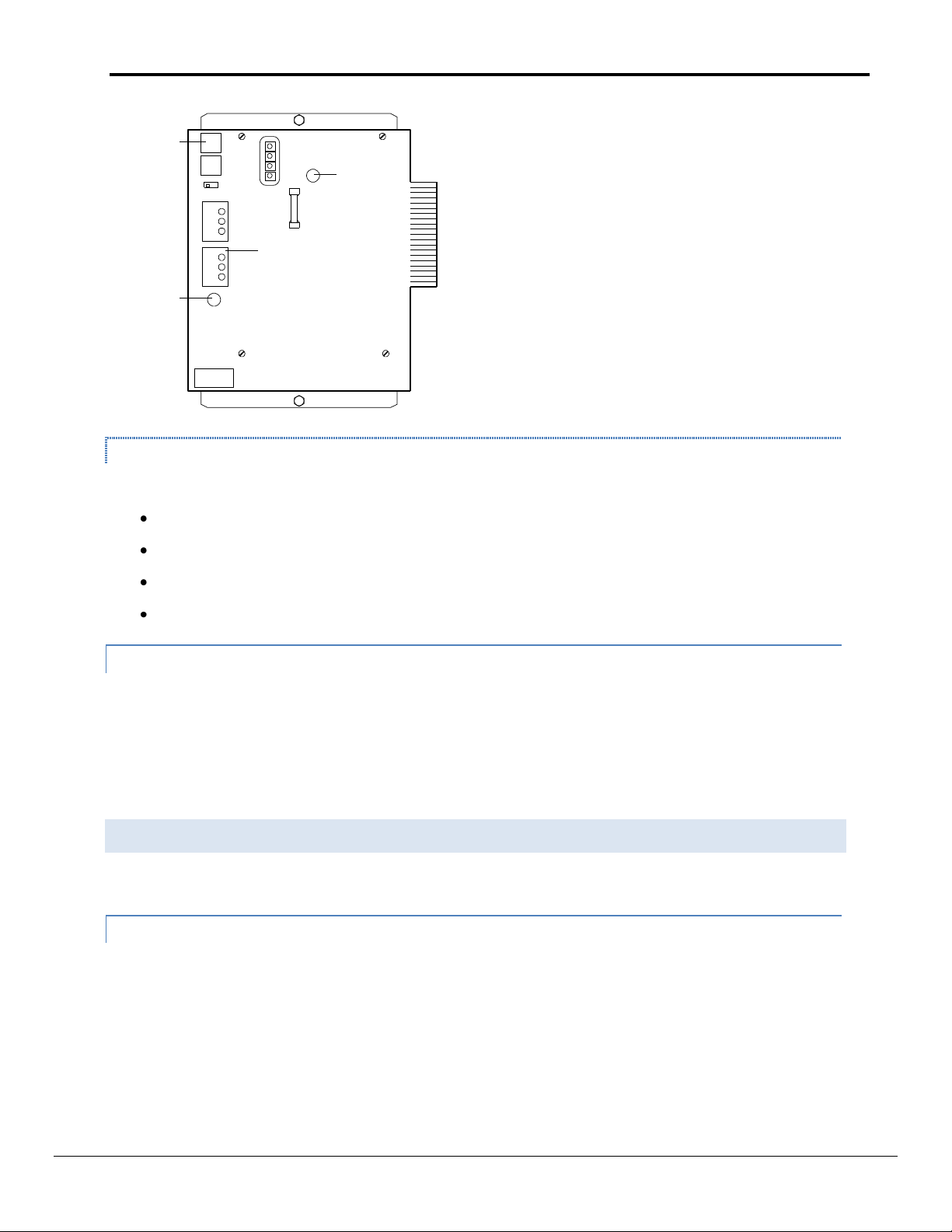
1.2.4.1 With level 3 devices (Unit Vents or WSHPs)
If a FieldServer gateway device is applied to a site that has an existing “MicroTech network” (meaning that it has
custom MicroTech Monitor software for that site and an NMP Panel) and Unit Vents or WSHPs, changes are
required as follows:
The checksums in the NMP’s application code must be corrupted so that the NMP no longer functions as a
Network Master Panel. The FieldServer device connects to the A port of the NMP.
Level 2 LMPs (Local Master Panel) must be removed from the network.
The RS-485 daisy chain connecting all of the Unit Vents or WSHPs must be connected directly to the “B”
port of the Level 1 NMP.
FieldServer Technologies 1991 Tarob Court Milpitas, California 95035 USA Web: www.fieldserver.com
Tel: (408) 262 2299 Fax: (408) 262 2269 Toll Free: (888) 509 1970 email: support@fieldserver.com
Page 8
McQuay Micro Tech Open Protocol Driver Manual Page 8 of 43
T
M
M
S
T
S
T
S
Level 1
Laptop PC
RS 232
RS 485
T
S
Port B
Port A
NMP
LMP
MCG RTU
LWC
Port B
Port A
Port B
Port B
Port B
Port A Port A
Port A
Level 2 Trunk
Level 2
Level 3
T
S
WSHP
Port B
Port A
T
S
WSHP
Port B
Port A
T
S
MT 2000
WSHP
Port B
Port A
T
S
Port B
Port A
MT 2000
WSHP
Different application code must be downloaded into all Unit Vents and WSHPs.
In the case of Unit Vents, the “Level 3 network code” for use in a MicroTech network must be
replaced with “Level 2 standalone” Unit Vent code.
In the case of WSHPs, the “Level 3” code for use in a MicroTech network must be replaced with
“Level 2 standalone” WSHP code.
See Figure 3 for details.
Figure 3. MicroTech Network Configurations with Level 1 NMP Supervisory Controller
Port Configuration
M=Master
S=Slave
T=TTY (for PC connection)
Notes:
A PC running MicroTechMonitor connects to an NMP through it’s a Port configured as “TTY”
The A Port of a Level 2 MCG is configured as “USER” to communicate with the MCG’s SLTA.
MicroTech WSHP’s on a MicroTech network require a LMP (Level 2 Local Master Panel) above them.
MicroTech 2000 WSHP’s with LonWorks code (vs LonMark code) are installed below an MCG.
FieldServer Technologies 1991 Tarob Court Milpitas, California 95035 USA Web: www.fieldserver.com
Tel: (408) 262 2299 Fax: (408) 262 2269 Toll Free: (888) 509 1970 email: support@fieldserver.com
Page 9

McQuay Micro Tech Open Protocol Driver Manual Page 9 of 43
1.2.4.2 With no level 3 devices
If a FieldServer gateway device is applied to a site that has an existing “MicroTech network” (meaning that it has
custom MicroTech Monitor software for that site and an NMP Panel) with only level 2 controllers and no level 3
devices (such as Unit Vents or WSHPs), changes are required as follows:
The checksums in the NMP’s application code must be corrupted so that the NMP no longer functions as a
Network master Panel. The FieldServer device connects to the “A” port of the NMP.
No network wiring changes are necessary
1.2.5 Existing MicroTech Open P ro tocol net work
If a FieldServer gateway device is applied to a site that has an existing “Open Protocol network”, the following
assumptions are made:
The site has either an OPM Panel or some other level 1 MicroTech controller that is functioning as an
OPM.
Any Unit Vents or WSHPs in the network are already running the proper “Level 2” application code
required for an “Open Protocol” network.
No network wiring changes are necessary.
See Figure 7 for details
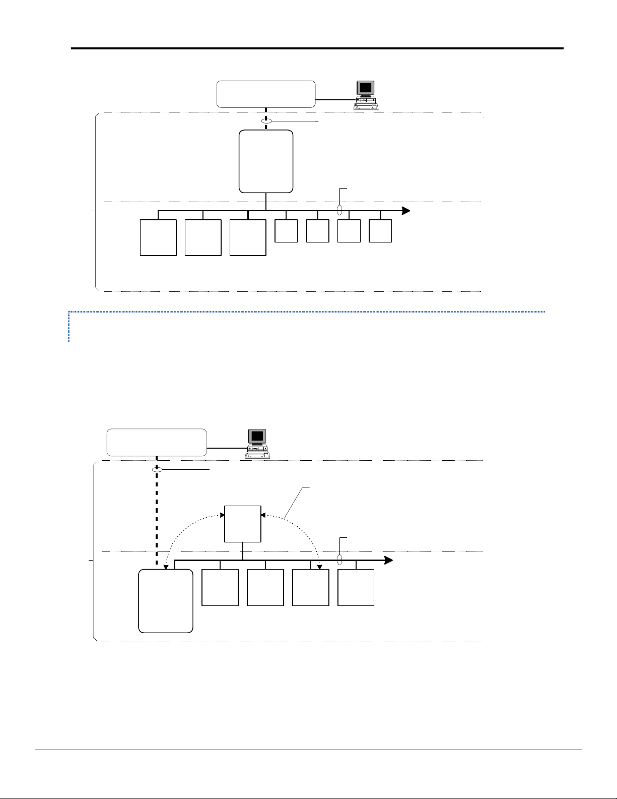
1.2.6 Replacin g a BACdrop Gat eway panel
1.2.6.1 Connected a Single Micro Tech unit controlle r
When a FieldServer device is used to replace a BACdrop panel that has been connected to one MicroTech unit
controller, some re-wiring is necessary. The RS-485 network terminals of the BACdrop panel are connected to the
“B” Port of the MicroTech controller, but the FieldServer connects to the “A” port of the MicroTech controller. The
unit controller will be a level 2 device with a Comm Port Configuration of “L2 TTY/Slave”. MicroTech Level 2
devices must have an address with a non-zero value to the left of the decimal point and "00" to the right of the
decimal point (for example, 01.00). For a level 2 device, the left side (the non-zero portion) of the address is set
with the controller's rotary hex switches.
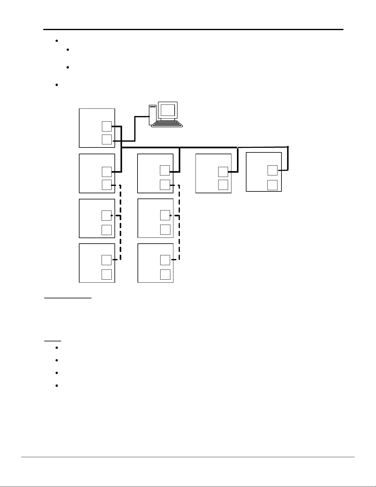
1.2.6.2 Connected to Multiple MicroTech unit control lers
When a FieldServer device is used to replace a BACdrop panel that has been connected to multiple MicroTech unit
controllers with no Level 1 supervisory panel such as an RMC, CSC, or RMS, a Level 1 device must be added. If the
unit controllers are 200 Series MicroTech, this can be accomplished by re-configuring one of the unit controllers to
be Level 1. The alternative to re-configuring one of the existing unit controllers to be a Level 1 device is to add a
level 1 device such as an OPM, RMC, CSC, or RMS, but this may be difficult because all of these control panels are
obsolete and no longer available. For a typical BACdrop network, the BACdrop panel is the level 1 controller and
the unit controllers are level 2 controllers. See Figures 4 and 6 for details.
FieldServer Technologies 1991 Tarob Court Milpitas, California 95035 USA Web: www.fieldserver.com
Tel: (408) 262 2299 Fax: (408) 262 2269 Toll Free: (888) 509 1970 email: support@fieldserver.com
Page 10
McQuay Micro Tech Open Protocol Driver Manual Page 10 of 43
RTU UV
Up to 63 MicroTech
controllers per BACdrop
BACnet on ISO 8802-3 (Ethernet), 10BaseT
MicroTech
BACdrop
(level 1)
Chiller UV UV UVSCU
Level 2
MicroTech
Level 1
BACnet BAS
by others
Main "front end"
PC for BAS
MicroTech network (RS-485)
Chiller
Level 2
MicroTech
Up to 63 MicroTech
controllers per BACdrop
BACnet BAS
by others
BACnet on ISO 8802-3 (Ethernet), 10BaseT
MicroTech
BACdrop
(level 2)
Level 1
ChillerChiller
Main "front end"
PC for BAS
CSC
Chiller
MicroTech network (RS-485)
All data requests from BACnet BAS to
MicroTech level-2 controllers are routed
through level-1 MicroTech controller
Figure 4. MicroTech Architecture
1.2.6.3 Connected to multiple MicroTech unit controllers and a supervisory panel su ch as an RMC,
CSC, or RMS panel
When a FieldServer device will be replacing a BACdrop Gateway panel that was connected to multiple MicroTech
unit controllers with a Level 1 supervisory panel such as an RMC, CSC, or RMS, some re-wiring may be necessary.
The FieldServer device must be wired to the A Port of the Level 1 device. The B Port of the Level 1 device is then
wired to the B Port of all Level 2 devices with a daisy chain. See Figure 5 for details.
Figure 5. Level 2 BACdrop Panel with Level 1 Supervisory Panel
FieldServer Technologies 1991 Tarob Court Milpitas, California 95035 USA Web: www.fieldserver.com
Tel: (408) 262 2299 Fax: (408) 262 2269 Toll Free: (888) 509 1970 email: support@fieldserver.com
Page 11
McQuay Micro Tech Open Protocol Driver Manual Page 11 of 43
TS2
BACdrop
Hot
Neutral
100 – 240 Vac
Power
L2
L1
GRD
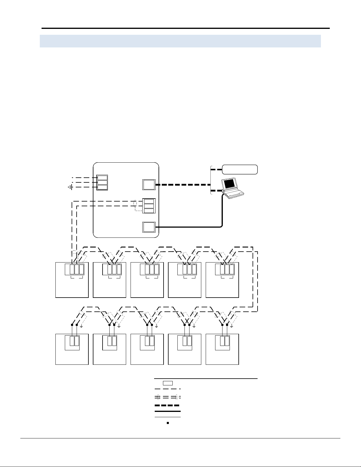
Notes:
1. Twisted, shielded pair cable must meet the following
minimum requirements: 300 V, 60°C, 20 AWG, polyethylene
insulated, with a PVC outer jacket and drain wire (Belden
8762 or equivalent). Some local codes may require the use
of plenum rated cable.
2. 10BaseT Ethernet cable. To directly connect a PC to the
Ethernet port, a hub or a special crossover cable must be
used.
3. Cable length must not exceed 5000 ft (1524 m).
4. Standard serial cable. A null modem is not required.
See notes 1 & 3
Self-contained AC
Port B
GND
TB7
Reciprocating
chiller
Port B
139
TB4
Screw chiller
Port B
55
BLK
WHT
B+
B–
138
137
54
53
Comm B
UVC (325)
1
2
PNK
GRY
Comm B
UVC (125)
4
5
PNK
GRY
RJ-45
3rd-party BAS
See note 2
TB1
Centrifugal chiller
(series 200)
Port B
858684
TB2
Applied rooftop
Port B
130
128
129
Legend
Field wiring terminal
Field wiring: discrete
Factory wiring
Field wiring: twisted, shielded pair cable
with drain wire (see note 1)
B+
Crimp or solder splice
BLK
WHT
BLK
WHT
BLK
WHT
BLK
WHT
BLK
WHT
BLK
WHT
BLK
WHT
BLK
WHT
BLK
WHT
Comm B
UVC (325)
1
2
PNK
GRY
Comm B
UVC (325)
1
2
PNK
GRY
Comm B
UVC (325)
1
2
PNK
GRY
Ethernet
DB9
PC
PC
+
–
GRD
Network
See note 4
Field wiring: 10BaseT Ethernet
Standard serial cable
1.3 MicroTech Comm unicat ion Port Configuration
In addition to the rules about MicroTech architecture and addressing, there is also a critical parameter called the
Comm Port Configuration. The Comm Port Configuration must also be set correctly for a unit controller to be able
to communicate. This comm port configuration for level 1 devices is different to level 2 devices. While it is
necessary to know this for proper unit controller setup and for troubleshooting communication problems, it is not
critical from the FieldServer side for programming or routing.
A level 1 device must have its communication port configuration set up as “Level 1 TTY/Slave”. To change this
configuration, connect to the unit controller with MicroTech Monitor software through the “A” port, proceed to
the “Read/Write” screen, read memory address “0A11”, and change the value to “C1” (Level 1 TTY/Slave). After
doing this, the controller must also have its rotary hex switches set to the Level 1 address of “00” to make the unit
controller’s network address 00.00. Please note that power must be cycled to the controller for this new hex
switch setting to take effect.
Figure 6. MicroTech Network with BACdrop Panel as Level 1 Device
FieldServer Technologies 1991 Tarob Court Milpitas, California 95035 USA Web: www.fieldserver.com
Tel: (408) 262 2299 Fax: (408) 262 2269 Toll Free: (888) 509 1970 email: support@fieldserver.com
Page 12
McQuay Micro Tech Open Protocol Driver Manual Page 12 of 43
Document
Description
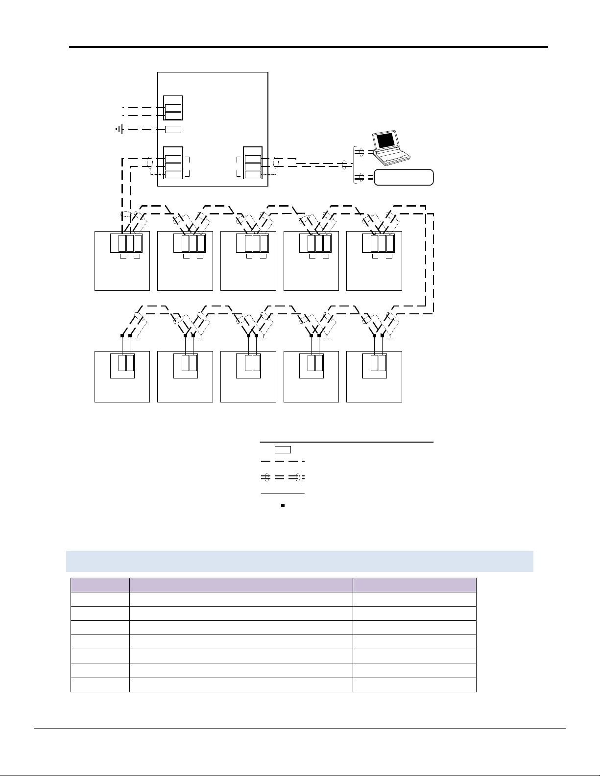
Location
IM 474
Open Protocol Master (OPM) Panel
www.mcquay.com
IM 689
BACdrop Gateway for MicroTech
www.mcquay.com
IM 658
Network Master Panel (NMP)
Contact McQuay
CD 573875Y
Microtech Open Protocol Wiring Diagrams
Contact McQuay
IM 444
Remote Monitoring and Control (RMC) Panel
Contact McQuay
IM 498
Remote Monitoring and Sequencing (RMS) Panel
Contact McQuay
IM 618
MicroTech Chiller System Controller (CSC) Panel
Contact McQuay
*Or other Level 1 Device (CSC, etc.)
Figure 7. MicroTech Network with OPM Panel as Level 1 Device
1.4 Reference Documents
FieldServer Technologies 1991 Tarob Court Milpitas, California 95035 USA Web: www.fieldserver.com
Tel: (408) 262 2299 Fax: (408) 262 2269 Toll Free: (888) 509 1970 email: support@fieldserver.com
Page 13
McQuay Micro Tech Open Protocol Driver Manual Page 13 of 43
FieldServer Technologies Part #
Description
FS-8917-16
RJ45 to terminal connector cable.
Part #
Description
McQuay Motor Mount Connector for Port A connection
2 DRIVER FEATURES
When emulating a Client, the driver enables the FieldServer to request ‘Everything’ from the McQuay, allow
specific fields to be read or written and apply device scaling to be applied.
When emulating a Server, the driver provides an emulation of the byte memory of a device and responds to read
and write requests.
The following important points and limitations should be noted.
Arising from a feature of the McQuay MicroTech® Open Protocol is the peculiarity that when a multi-byte
value is written to a McQuay device, the write is done one byte at a time (one byte of data can be
transferred per poll/response message pair) allowing for the possibility that the multi byte value is only
partially correct until all the messages have been completed.
The vendor equipment is limited to a maximum of 9600 baud. Given that each message packet can only
transfer one byte of data and that some data of interest is multi-byte, users of this protocol should expect
low data transfer rates.
Port expansion is not supported for this driver.
Each MicroTech® controller is shipped from the factory with a unique job site password. The passwords
are provided by the McQuay International representative at the time of startup.
The driver does not validate passwords when configured as a Server. This means that requests to read or
write data will succeed even if the password supplied with the request is incorrect.
3 DRIVER SCOPE OF SUPPLY
3.1 Sup plied by FieldServ er Technologies for this driver
3.2 Provided by Supplier of 3
rd
Party Equipment
FieldServer Technologies 1991 Tarob Court Milpitas, California 95035 USA Web: www.fieldserver.com
Tel: (408) 262 2299 Fax: (408) 262 2269 Toll Free: (888) 509 1970 email: support@fieldserver.com
Page 14

McQuay Micro Tech Open Protocol Driver Manual Page 14 of 43
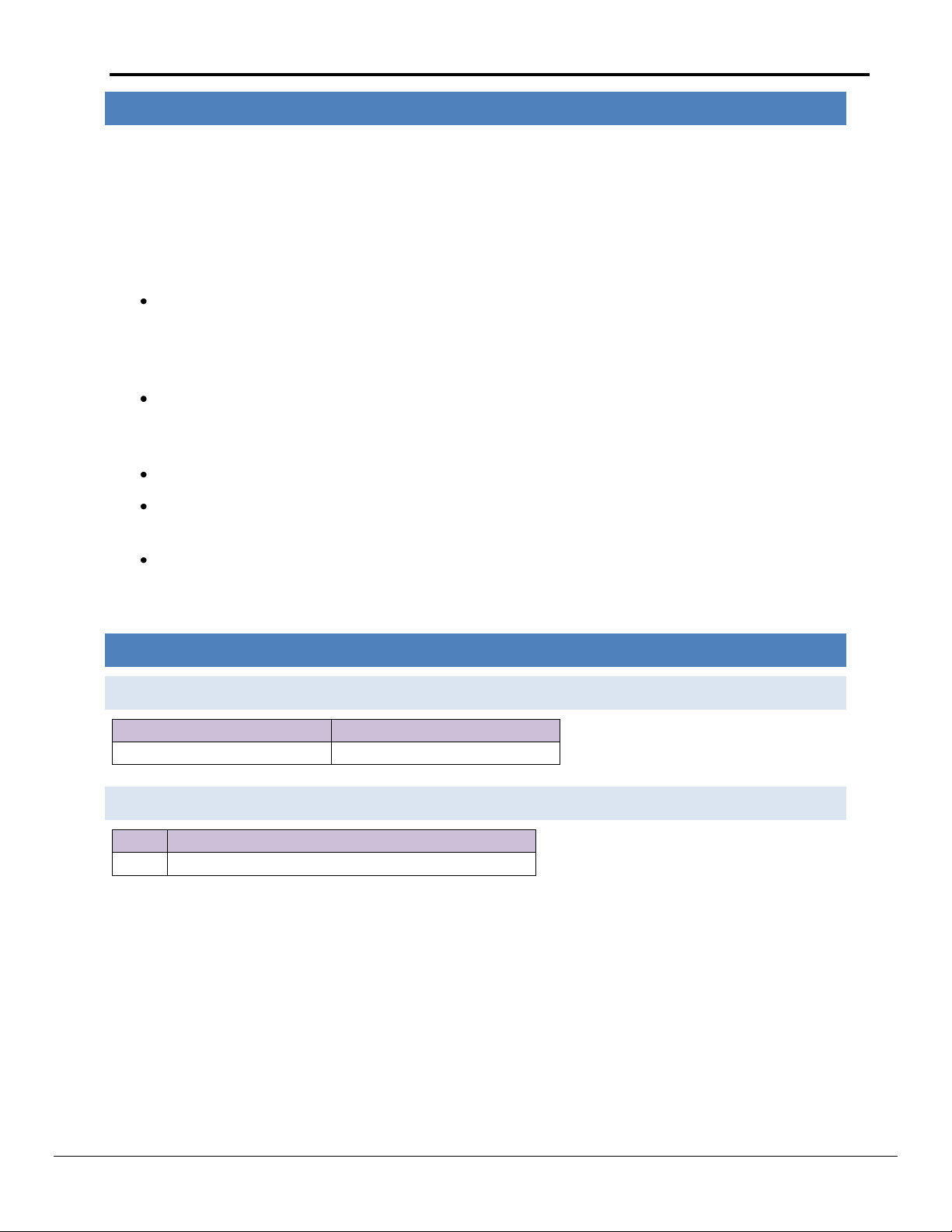
FS-8917-16
RJ45-04
BLUE/WHITE
RJ45-08
ORANGE/WHITE
SERIES 200 CONTROLLER
FS-COM
RJ45-01
BROWN
FS-Tx/+
FS-Rx/-
FieldServer
Connect to one of the RS-232
Ports on the FieldServer
P1
18
4 HARDWARE CONNECTIONS
The FieldServer is connected to the McQuay device as shown below.
Configure the McQuay device according to manufacturer’s instructions.
FieldServer Technologies 1991 Tarob Court Milpitas, California 95035 USA Web: www.fieldserver.com
Tel: (408) 262 2299 Fax: (408) 262 2269 Toll Free: (888) 509 1970 email: support@fieldserver.com
Page 15

McQuay Micro Tech Open Protocol Driver Manual Page 15 of 43
Section Title
Data_Arrays
Column Title
Function
Legal Values
Data_Array_Name
Provide name for Data Array
Up to 15 alphanumeric characters
Data_Array_Format
Provide data format. Each Data Array can only take
on one format.
FLOAT, BIT, UInt16, SInt16,
Packed_Bit, Byte, Packed_Byte,
Swapped_Byte
Data_Array_Length
Number of Data Objects. Must be larger than the
data storage area required by the Map Descriptors
for the data being placed in this array.
1-10, 000
// Data Arrays
Data_Arrays
Data_Array_Name
, Data_Array_Format
, Data_Array_Length
DA_AI_01
, UInt16,
, 200
DA_AO_01
, UInt16
, 200
DA_DI_01
, Bit
, 200
DA_DO_01
, Bit
, 200
5 DATA ARRAY PARAMETERS
Data Arrays are “protocol neutral” data buffers for storage of data to be passed between protocols. It is necessary
to declare the data format of each of the Data Arrays to facilitate correct storage of the relevant data.
Example
FieldServer Technologies 1991 Tarob Court Milpitas, California 95035 USA Web: www.fieldserver.com
Tel: (408) 262 2299 Fax: (408) 262 2269 Toll Free: (888) 509 1970 email: support@fieldserver.com
Page 16

McQuay Micro Tech Open Protocol Driver Manual Page 16 of 43
Section Title
Connections
Column Title
Function
Legal Values
Port
Specify which port the device is connected to
the FieldServer
P1-P8, R1-R21
Baud*
Specify baud rate
300, 1200, 2400, 4800, 9600 (Vendor
limitation).
Parity*
Specify parity
Even (Vendor limitation)
Data_Bits*
Specify data bits
7 (Vendor limitation)
Stop_Bits*
Specify stop bits
1
Protocol
Specify protocol used
MCQ, McQuay
Poll Delay*
Time between internal polls
0-32000 s, 1s
// Client Side Connections
Connections
Port
, Baud
, Parity
, Data_Bits
, Protocol
, Poll_Delay
P1
, 9600
, Even
, 7
, McQuay
, 0.100s
6 CONFIGURING THE FIELDSERVER AS A MCQUAY MICRO TECH OPEN PROTOCOL CLIENT
For a detailed discussion on FieldServer configuration, please refer to the FieldServer Configuration Manual. The
information that follows describes how to expand upon the factory defaults provided in the configuration files
included with the FieldServer. (See “.csv” sample files provided with the FieldServer).
This section documents and describes the parameters necessary for configuring the FieldServer to communicate
with a McQuay Micro Tech Open Protocol Server.
The configuration file tells the FieldServer about its interfaces, and the routing of data required. In order to enable
the FieldServer for McQuay Micro Tech Open Protocol communications, the driver independent FieldServer buffers
need to be declared in the “Data Arrays” section, the destination device addresses need to be declared in the
“Client Side Nodes” section, and the data required from the Servers needs to be mapped in the “Client Side Map
Descriptors” section. Details on how to do this can be found below.
Note that in the tables, * indicates an optional parameter, with the bold legal value being the default.
6.1 Client Side Connectio n Parameters
Example
1
Not all ports shown are necessarily supported by the hardware. Consult the appropriate Instruction manual for details of the ports available
on specific hardware.
FieldServer Technologies 1991 Tarob Court Milpitas, California 95035 USA Web: www.fieldserver.com
Tel: (408) 262 2299 Fax: (408) 262 2269 Toll Free: (888) 509 1970 email: support@fieldserver.com
Page 17

McQuay Micro Tech Open Protocol Driver Manual Page 17 of 43
Section Title
Nodes
Column Title
Function
Legal Values
Node_Name
Provide name for Node
Up to 32 alphanumeric
characters
Protocol
Specify protocol used
MCQ, McQuay
Port
Specify which port the device is connected to the FieldServer
P1-P8, R1-R22
PLC_Type
The name of the McQuay Equipment type being polled. The
equipment type must be known for the driver to operate
correctly.
200CFC, 100CFC, 050RPC,
001ASC, 000SCU, TypeUnknown
Password
Maximum of 8 characters.
Ascii characters only.
Node_Hi
Specify the rotary Hi address switch setting of the Mcquay
controller
0 to F
Node_Lo
Specify the rotary Lo address switch setting of the Mcquay
controller
0 to F
// Client Side Nodes
Nodes
Node_Name
, Node_Hi
, Node_Lo
, Protocol
, Port
, Password
, PLC_Type
Node_200CFC
, 3
, B
, McQuay
, P1
, 85760430
, 200CFC
6.2 Client Side Node Param eters
2
Not all ports shown are necessarily supported by the hardware. Consult the appropriate Instruction manual for details of the ports available
on specific hardware.
FieldServer Technologies 1991 Tarob Court Milpitas, California 95035 USA Web: www.fieldserver.com
Tel: (408) 262 2299 Fax: (408) 262 2269 Toll Free: (888) 509 1970 email: support@fieldserver.com
Page 18

McQuay Micro Tech Open Protocol Driver Manual Page 18 of 43
Column Title
Function
Legal Values
Map_Descriptor_Name
Name of this Map Descriptor
Up to 32 alphanumeric characters
Data_Array_Name
Name of Data Array where data is to be
stored in the FieldServer
One of the Data Array Names
specified in Section 5.
Data_Array_Offset
Starting location in Data Array
0 to maximum specified in Section 5.
Function
Function of Client Map Descriptor
Rdbc, Wrbc, Wrbx
Column Title
Function
Legal Values
Node_Name
Name of Node to fetch data from
One of the Node
Names specified
in Section 6.2.
Length*
This parameter normally refers to the length of Map Descriptor. Since
one data field can be read or written per poll/response sequence, the
driver assumes a length of 1. When Bytes_Per_Field is specified, must be
set to 1. When used to read addresses (Appendix A.3), this parameter is
used to specify the number of data elements to be read.
Any positive
integer, 1.
Field_Name*
The name of the data field of interest. Each address with meaningful
data in the McQuay device has a name. The field names are defined in a
specification for each device type. If the field name is unknown, the
Address can be defined. Refer to Appendix A.2 for further information.
A field name
from Appendix
C.3, Everything,
Device_Scaling*
If set to No then the driver stores the raw values, if set to Yes, the data is
scaled before storing. Refer to Appendix A.1.2 for information on the
device scaling applied. Note that ‘Device_Scaling’ has no meaning when
writing to a McQuay device. The Device_Scaling keyword needs to be
used in conjunction with Field_Name
Yes, No
Address*
The address in the McQuay device that contains the data of interest. .
Used with direct addressing – refer to Appendix A.2.
Any positive
integer, -
Bytes_Per_Field*
This parameter is used with direct addressing. When reading, up to 4
consecutive address locations in the McQuay device can be combined
and stored in a single Data Array element. When writing, one value from
the Data Array may be sent to up to 4 consecutive address locations in
the McQuay device. Refer to Appendix A.2 for more information. If this
parameter is specified, length must be set to 1.
1, 2, 3, 4
Column Title
Function
Legal Values
Scan_Interval
Rate at which data is polled
>0.1s
6.3 Client Side Map Descri ptors
6.3.1 Field Server Related Ma p Descriptor Parame ters
6.3.2 Drive r Related Map Descripto r Parameters
6.3.3 Timing P arameters
FieldServer Technologies 1991 Tarob Court Milpitas, California 95035 USA Web: www.fieldserver.com
Tel: (408) 262 2299 Fax: (408) 262 2269 Toll Free: (888) 509 1970 email: support@fieldserver.com
Page 19

McQuay Micro Tech Open Protocol Driver Manual Page 19 of 43
Map_Descriptor_Name
, Data_Array_Name
, Data_Array_Offset
, Function
, Node_Name
, Length
, Scan_Interval
, Field_Name
, Device_Scaling
Read Chiller 1
, DA_CHILLER1
, 0
, Rdbc
, Chiller1
, 1
, 1.0s
, Everything
, Yes
Map_Descriptor_Name
, Data_Array_Name
, Data_Array_Offset
, Function
, Scan_Interval
, Node_Name
, Length
, Field_Name
Chiller10_Op_Mode
, DA_OPERATIONAL_MODES
, 10
, Rdbc
, 0s
, Chiller10
, 1
, Chiller Operation Mode
Many validation or
error messages report
the name of the Map
Descriptor in the
message and, thus it is
strongly recommended
that unique names be
used.
Each field read has its
value stored in this
Data Array. The
location is dependent
on the field name. The
length of the Data
Array should be at least
200, so that all
parameters can be
stored.
The driver will read
every data field
known for the
device.
The values will be scaled
before storage.
Example: The ‘Evaporator
Refrigerant Pressure’ will be
stored by dividing the raw
value read by 10.
This parameter
connects the Map
Descriptor to a
Node which in turn
connects the Map
Descriptor to a port.
Ensure that the field name is spaced and spelled exactly as it is
printed in Appendix C.3
6.3.4 Map D escriptor Example 1 – Read Everything.
In this example the Map Descriptor tells the driver to read all data fields known for the Node. The data fields are read sequentially and the values placed in the
Data Array at a location determined by the driver. Appendix C.3 outlines the data read and the Data Array location of each field. There is no way of telling this
command to read some fields more often than others. Each field is read in turn and when the end of the list is reached the driver starts at the beginning again.
6.3.5 Map D escriptor Example 2 – Read a particular Data Field.
This example illustrates how to read data for one particular field of interest. The data is read every 2.0 seconds and the value obtained is stored in the Data
Array named DA_OPERATIONAL_MODES at location 10.
FieldServer Technologies 1991 Tarob Court Milpitas, California 95035 USA Web: www.fieldserver.com
Tel: (408) 262 2299 Fax: (408) 262 2269 Toll Free: (888) 509 1970 email: support@fieldserver.com
Page 20

McQuay Micro Tech Open Protocol Driver Manual Page 20 of 43
Map_Descriptor_Name
, Data_Array_Name
, Data_Array_Offset
, Function
, Node_Name
, Length
, Field_Name
Chiller1_Op_Mode
, DA_MODES
, 0
, Wrbx
, Chiller1
, 1
, Chiller Operation Mode
The data is only written
when the contents of
element zero of the array
named DA_MODES
changes.
The name of the
data field to be
written to.
6.3.6 Map D escriptor Example 3 – Write.
In this example data is written to control fields in the McQuay device using the Wrbx (write on change) function. A write message will be generated each time
the data at index 0 in the Data Array changes. When writing multibyte fields, several messages are required to transfer the byte values to the McQuay devices.
Note that ‘Device_Scaling’ has no meaning when writing to a McQuay device. The user must ensure that valid numbers are written to the data fields.
FieldServer Technologies 1991 Tarob Court Milpitas, California 95035 USA Web: www.fieldserver.com
Tel: (408) 262 2299 Fax: (408) 262 2269 Toll Free: (888) 509 1970 email: support@fieldserver.com
Page 21

McQuay Micro Tech Open Protocol Driver Manual Page 21 of 43
Section Title
Connections
Column Title
Function
Legal Values
Port
Specify which port the device is connected to
the FieldServer
P1-P8, R1-R23
Baud*
Specify baud rate
300, 1200, 2400, 4800, 9600 (Vendor
limitation)
Parity*
Specify parity
Even (Vendor limitation)
Data_Bits*
Specify data bits
7 (Vendor limitation)
Stop_Bits*
Specify stop bits
1(Vendor limitation)
Protocol
Specify protocol used
MCQ, McQuay
// Server Side Connections
Connections
Port
, Baud
, Parity
, Data_Bits
, Protocol
, Stop_Bits
, Poll_Delay
P1
, 9600
, Even
, 7
, McQuay
, 1
, 0.100s
7 CONFIGURING THE FIELDSERVER AS A MCQUAY MICRO TECH OPEN PROTOCOL
SERVER
7.1 Server Side Connection Paramaters
Example
3
Not all ports shown are necessarily supported by the hardware. Consult the appropriate Instruction manual for details of the ports available
on specific hardware.
FieldServer Technologies 1991 Tarob Court Milpitas, California 95035 USA Web: www.fieldserver.com
Tel: (408) 262 2299 Fax: (408) 262 2269 Toll Free: (888) 509 1970 email: support@fieldserver.com
Page 22

McQuay Micro Tech Open Protocol Driver Manual Page 22 of 43
Section Title
Nodes
Column Title
Function
Legal Values
Node_Name
Provide name for node
Up to 32 alphanumeric characters
Protocol
Specify protocol used
MCQ, McQuay
Port*
Specify which port the device is connected
to the FieldServer. This parameter is
optional for Server side nodes. The reason
is that when a poll is received on any port
an attempt will be made to match it
against any Map Descriptor/node
irrespective of the port. If emulating more
than one Node with the same address,
however, the Nodes must be linked to
specific ports.
P1-P8, R1-R24
PLC_Type
This parameter has no meaning for a
Server but it must be specified to allow the
driver to complete its configuration file
validation.
200CFC, 100CFC, 050RPC, 001ASC, 000SCU, TypeUnknown
Password*
This parameter is ignored for a Server.
Although every poll contains a password,
this driver does no password validation
when configured as a Server.
Ascii characters only.
Node_Hi
Specify the rotary Hi address switch
setting of the Mcquay controller
0 to F
Node_Lo
Specify the rotary Lo address switch
setting of the Mcquay controller
0 to F
// Server Side Nodes
Nodes
Node_Name
, Node_Hi
, Node_Lo
, Protocol
, PLC_Type
, Password
Node_A
, 3
, B
, McQuay
, 200CFC
, 85760430
Column Title
Function
Legal Values
Map_Descriptor_Name
Name of this Map Descriptor
Up to 32 alphanumeric characters
7.2 Server Side Node P arameters
Example
7.3 Server Side Map Descri ptors
7.3.1 Field Server Specific M a p Descriptor Param eters
4
Not all ports shown are necessarily supported by the hardware. Consult the appropriate Instruction manual for details of the ports available
on specific hardware.
FieldServer Technologies 1991 Tarob Court Milpitas, California 95035 USA Web: www.fieldserver.com
Tel: (408) 262 2299 Fax: (408) 262 2269 Toll Free: (888) 509 1970 email: support@fieldserver.com
Page 23

McQuay Micro Tech Open Protocol Driver Manual Page 23 of 43
Data_Array_Name
Name of Data Array where data is to be
stored in the FieldServer
One of the Data Array names from
Section 5
Data_Array_Offset
Starting location in Data Array
0 to (Data_Array_Length -1) as specified
in Section 5
Function
Function of Client Map Descriptor
Passive
Column Title
Function
Legal Values
Node_Name
Name of Node to fetch data from
One of the Node Names
specified in Section 7.2
Length
Length of Map Descriptor
1-10000
Address
Starting address of read block. Addresses cannot be specified
in hexadecimal format.
Any positive integer
Column Title
Function
Legal Values
Scada_Hold_Timeout
Specifies time Server side waits before responding to Client that
node is offline on FieldServer Client side.
>1.0s
7.3.2 Drive r Specific Map Desc ript or Parameters
7.3.3 Timing P arameters
FieldServer Technologies 1991 Tarob Court Milpitas, California 95035 USA Web: www.fieldserver.com
Tel: (408) 262 2299 Fax: (408) 262 2269 Toll Free: (888) 509 1970 email: support@fieldserver.com
Page 24

McQuay Micro Tech Open Protocol Driver Manual Page 24 of 43
Map_Descriptor_Name
, Data_Array_Name
, Data_Array_Offset
, Function
, Node_Name
, Address
, Length
Chiller1_emulation
, DA_CHILLER1
, 0
, Passive
, Chiller1
, 1
, 10000
Map_Descriptor_Name
, Data_Array_Name
, Data_Array_Offset
, Function
, Node_Name
, Address
, Length
Chiller1_emulation1
, DA_CHILLER1
, 0
, Passive
, Chiller1
, 1024
, 256
Chiller1_emulation2
, DA_CHILLER1
, 256
, Passive
, Chiller1
, 2048
, 256
Ensure that Data Array’s
length is at least as long as
the Map Descriptor’s.
A data format of BYTE is
appropriate.
Passive means that the Map
Descriptor responds to polls but
does not generate any polls itself.
The Node name connects the
Map Descriptor to a Node
definition and possibly to a port.
10, 000 is the maximum length of a
Data Array so there is no point in
making the Map Descriptor longer.
The same Data
Array is used for
both Map
Descriptors.
By using the same
Data Array and
changing the offset
the data can all be
packed into a
smaller array.
1024 = 0x400; 2048 = 0x800
These two address ranges cover almost all the data fields in a 200 series chiller.
A few more Map Descriptors could be added to serve the remaining data field
addresses.
7.3.4 Map D escriptor Example – Strategy 1.
This example illustrates the configuration of the FieldServer as a McQuay Micro Tech Open Protocol Server where a single Map Descriptor is used to emulate a
McQuay device’s memory as one large single block of bytes. Any requests in the address range 1 -0x270F can be serviced by this one Map Descriptor. Is has
the drawback that a large Data Array which will be mostly empty is used. This does not affect performance but uses the FieldServer’s memory resource.
When a poll is received, the driver looks through the Map Descriptor and finds one with a matching Node and one whose address and length cover the poll’s
address.
7.3.5 Map D escriptor Example – Strategy 2.
In this example the memory being emulated is divided into chunks to avoid having a large sparse array. When a poll is received, the driver looks through the
Map Descriptors and finds one with a matching Node and one whose address and length cover the poll’s address.
FieldServer Technologies 1991 Tarob Court Milpitas, California 95035 USA Web: www.fieldserver.com
Tel: (408) 262 2299 Fax: (408) 262 2269 Toll Free: (888) 509 1970 email: support@fieldserver.com
Page 25

McQuay Micro Tech Open Protocol Driver Manual Page 25 of 43
Map_Descriptors
Map_Descriptor_Name
, Data_Array_Name
, Data_Array_Offset
, Function
, Node_Name
, Address
, Length
, Field_Name
, Device_Scaling
, Scan_Interval
Read_field1
, DA_TEMP_SCALED
, 0
, Rdbc
, Node_200CFC
, 1
, 1
, Outdoor Air Temperature - BAS
, Yes
, 9.5s
Appendix A. Useful Features
Appendix A.1. Scaling
Appendix A.1.1. User Scali n g :
The user can specify scaling in the configuration file which allows a value to be scaled before being stored in a Data Array or after being extracted from a data for writing
to McQuay device. This scaling is specified by using the following keywords in Map Descriptor definition.
Data_Array_Low_Scale,
Data_Array_High_Scale,
Device_Low_Scale,
Device_High_Scale…..
Appendix A.1.2. Device Scal i n g:
The raw values read from a McQuay device may be treated as raw values or they may be scaled. Device scaling is the term used to describe the hard-coded scaling
specified by McQuay for each data field. By applying device scaling the user can avoid details or knowledge of the scaling and used the converted value directly.
If this scaling is required then use the Device_Scaling parameter (see 6.3.2). Note that this parameter needs to be used in conjunction with Field_Name.
There are 5 device scaling methods. Refer to Appendix C.4 and Appendix C.5 for information on the application of these parameters.
Note that when device scaling is applied it is applied without consideration of the raw value. Where the raw value has a special meaning (available in the McQuay packet
documents for the equipment type of interest); this driver does not apply any special consideration to these special values.
As a Client: - Device and User scaling may be applied.
As a Server. Device Scaling and User scaling is not applied. The raw value written to any data location is stored as is and the raw value read from a Data Array used in
formatting the response to a read.
FieldServer Technologies 1991 Tarob Court Milpitas, California 95035 USA Web: www.fieldserver.com
Tel: (408) 262 2299 Fax: (408) 262 2269 Toll Free: (888) 509 1970 email: support@fieldserver.com
Page 26

McQuay Micro Tech Open Protocol Driver Manual Page 26 of 43
Appendix A.2. Direct Addressing
Direct addressing allows data to be read from the McQuay device when the field name is unknown. McQuay
specifies the addresses in hexadecimal notation but they must be specified in the CSV file in decimal format. For
example, to read McQuay address 0x0400, the address in the CSV file must be entered as 1024.
If reading multiple addressing at once (i.e. if the length is greater than 1) it may be necessary to adjust the timeout
for the Map Descriptor.
It is possible to read multiple addresses using one Map Descriptorbut it is only possible to write to a single address.
Refer to examples on the following pages.
FieldServer Technologies 1991 Tarob Court Milpitas, California 95035 USA Web: www.fieldserver.com
Tel: (408) 262 2299 Fax: (408) 262 2269 Toll Free: (888) 509 1970 email: support@fieldserver.com
Page 27

McQuay Micro Tech Open Protocol Driver Manual Page 27 of 43
Map_Descriptor_Name
, Data_Array_Name
, Data_Array_Offset
, Node_Name
, Address
, Length
, Scan_Interval
, Function
Chiller1_emulation
, DA_CHILLER1
, 0
, Chiller1
, 4096
, 10
, 1.0s
, Rdbc
Map_Descriptor_Name
, Data_Array_Name
, Data_Array_Offset
, Node_Name
, Address
, Length
, Bytes_per_Field
, Scan_Interval
, Function
Chiller1_emulation
, DA_CHILLER1
, 0
, Chiller1
, 4096
, 1
, 4
, 1.0s
, Rdbc
Specify the address
in decimal
A data format of
BYTE is appropriate,
Specify the address
in decimal
Length must be set
to 1 when
Bytes_per_Field is
specified.
A value between 1 and 4 - tells
the driver how many consecutive
addresses to read from the
remote device. The data value for
each address is combined into a
single value before it is stored.
Appendix A.3. Direct Addressing Example 1– Reading direct address.
This example reads 10 data elements from a McQuay device starting at address 4096 (= 0x1000). The 10 values obtained are stored in DA_CHILLER1 starting at
offset zero.
Appendix A.4. Direct Addressing Example 2 – Controlling Bytes per Field – Reading
This example reads a McQuay device starting at address 4096 (= 0x1000) to 4099 incl. Before storing the data from the responses, the FieldServer combines
the 4 values into a single value and stores this single value in a single Data Array element.
The driver reads address 4096 and gets a value. Call this value v0.
The driver reads address 4097 and gets a value. Call this value v1.
The driver reads address 4098 and gets a value. Call this value v2.
The driver reads address 4099 and gets a value. Call this value v3.
When the 4th address has been read, the driver calculates Total_Value = v0 + v1 * 0x100 + v2 * 0x10000 + v3 * 0x1000000. The Total_Value is stored in the
Data Array.
FieldServer Technologies 1991 Tarob Court Milpitas, California 95035 USA Web: www.fieldserver.com
Tel: (408) 262 2299 Fax: (408) 262 2269 Toll Free: (888) 509 1970 email: support@fieldserver.com
Page 28

McQuay Micro Tech Open Protocol Driver Manual Page 28 of 43
Map_Descriptor_Name
, Data_Array_Name
, Data_Array_Offset
, Node_Name
, Address
, Length
, Bytes_Per_Field
, Scan_Interval
, Function
Chiller1_emulation
, DA_CHILLER1
, 0
, Chiller1
, 4096
, 1
, 2
, 1.0s
, Wrbc
Specify the address
in decimal
Length must be set
to 1 when
Bytes_Per_Field is
specified.
A value from 1 to 4 -tells the
driver how many consecutive
addresses to write to The data
value written to each address is
based on the single value
extracted from offset 0 in the
Data Array DA_CHILLER1
Appendix A.5. Advanced Map Descriptor Example 3 – Controlling Bytes per Field – Writing
This example writes to a McQuay device starting at address 4096 (= 0x1000) to 4097incl. The value written to each address location is based on a single value
extracted from the FieldServer’s Data Arrays.
The value v0 = (value_extracted_from_DA) AND 0xff
The value v1 = (value_extracted_from_DA shift right by 8) AND 0xff
The driver writes value v0 to address 4096.
The driver writes value v1 to address 4097.
FieldServer Technologies 1991 Tarob Court Milpitas, California 95035 USA Web: www.fieldserver.com
Tel: (408) 262 2299 Fax: (408) 262 2269 Toll Free: (888) 509 1970 email: support@fieldserver.com
Page 29

McQuay Micro Tech Open Protocol Driver Manual Page 29 of 43
Appendix B. Troubleshooting
Appendix B.1. Connection Problems
The driver produces a timeout each time a message is sent. If the number of timeouts is the same as the number
of messages sent then the McQuay device has never sent a response. The following reasons may be applicable:
Incorrect connection settings - the messages sent by the FieldServer cannot be interpreted by the
McQuay device.
Incorrect connection wiring – the McQuay device may require a jumper on its serial port to deflect
hardware handshaking. Refer to the vendor manual.
Serial port failure – If the Tx LED is not flashing each time a message is sent, the port is not working
The McQuay device is off.
If the Node_ID and Route are incorrect, the McQuay device will not respond at all.
Appendix B.2. Negative Acknowledgement - NAK
The Server sends a NAK message and increments the NAK stat each time a poll is unsuccessful. An occasional NAK
may indicate a corrupted message. If the number of NAK's is the same as the number of transmitted messages to
a Node, one of the following problems could apply:
Bad Password - the password specified in the "read" command did not match any of the access level
passwords stored in the MicroTech controller to which the terminal is connected. Call FST Tech support
for default passwords or call your Vendor. FST recommends checking the password first as in almost all
reports the problem was resolved by changing the password.
Device has been polled with an invalid command code.
Bad Node_ID / Route parameters for the node.
The MCQ device received the message and thought it was badly formatted. This is unlikely on a repeated
basis unless the connection settings were slightly wrong.
The packet structure was invalid
The packet was received with a parity or framing error
Appendix B.3. Node ID problems
If the Node is incorrectly specified, the FieldServer will not get a response from the McQuay unit. The ID used to
communicate with the McQuay unit needs to be determined. This may not be the same as shown on the Rotary
switches of the unit. Note that McQuay uses Hexadecimal notation for addressing, therefore, if connection to the
Unit is with address 0201, this is in Hex and the Node ID for the FieldServer configuration needs to be 513.
Use Node_Id=256 only if it is required that connected panel should respond regardless of its own internal address.
For Driver Versions 1.05a and later, the Node_ID parameter has been replaced with the Node_Hi/Node_Lo
Parameters. Refer to Sections 6.2and 7.2
FieldServer Technologies 1991 Tarob Court Milpitas, California 95035 USA Web: www.fieldserver.com
Tel: (408) 262 2299 Fax: (408) 262 2269 Toll Free: (888) 509 1970 email: support@fieldserver.com
Page 30

McQuay Micro Tech Open Protocol Driver Manual Page 30 of 43
Map_Descriptors
Map_Descriptor_Name
,
Data_Array_Name
,
Data_Array_Offset
,
Function
,
Node_Name
,
Address
,
Length
Supply Fan Status
, DA_AI_01
, 01
, Passive
, Node_A
, 1118
, 1
Supply Temp
, DA_AI_01
, 02
, Passive
, Node_A
, 1063
, 1
Space Temp
, DA_AI_01
, 03
, Passive
, Node_A
, 1066
, 1
Control Temp Part 1
, DA_AI_01
, 04
, Passive
, Node_A
, 1074
, 1
Connect FieldServer
to port A of the OPM
(RS-232 or RS-485
depending on the Port
A select)
Connect daisy chained
McQuay devices to
port B of the OPM
Set HI and LO rotary
switches on the OPM
to “00”
Appendix B.4. Server Side Configuration – Consecutive Addresses
Some variables have their values stored in two consecutive address locations. When the Client polls for the value it
actually sends two read messages – one for each address. When configuring the Server side, therefore, it is
necessary to define two Map Descriptors for variables which require two consecutive addresses.
Appendix B.5. Configuring the OPM to enable communication between the FieldServer and McQuay
devices
Appendix B.5.1. Con figu ring multip le McQuay d evices to c o mmunicat e to a Fi eldS e r ver
without an OPM:
The FieldServer will be wired to a Level 1 Microtech controller at port A. Port B of the Level 1 MicroTech controller
will be connected to the daisy chained Level 2 Microtech controllers. This has been tested with a SCU.
1. Power down the Microtech controller to be configured as Level 1. Set HI and LO rotary switches to “00”.
Power up the unit.
2. Connect the Microtech controller to a PC through Port A (RS-232).
3. Daisy chain other McQuay devices to Port B (RS-485)
FieldServer Technologies 1991 Tarob Court Milpitas, California 95035 USA Web: www.fieldserver.com
Tel: (408) 262 2299 Fax: (408) 262 2269 Toll Free: (888) 509 1970 email: support@fieldserver.com
Page 31

McQuay Micro Tech Open Protocol Driver Manual Page 31 of 43
4. Start McQuay Open Protocol Monitoring Software
5. Enter the User Name as “McQuay” and the password as ”SGC”
6. Once in the main menu, hit ‘F7’ to enter Advanced Features
7. Hit ‘F1’ to enter Read/Write Memory
8. Enter “b00.00” to change the Box Address (Node_HI and Node_LO) to “00”
9. Enter “w0A11 C1” to write C1 to memory address 0A11. This will set up the comm port configuration
with Port A as TTY and Port B as Master
10. Test if the wiring to the daisy chained devices is correct by doing the following:
o To read from a controller with the rotary hex switches set to “01”, change the box address to
01.00 and enter r0A11
o If you get a response, then it is wired correctly
o It is suggested that you read from each daisy chained controller
11. Shut down the McQuay Open Protocol Monitoring Software
12. Disconnect unit from the PC
13. Connect FieldServer to Port A (RS-232)
FieldServer Technologies 1991 Tarob Court Milpitas, California 95035 USA Web: www.fieldserver.com
Tel: (408) 262 2299 Fax: (408) 262 2269 Toll Free: (888) 509 1970 email: support@fieldserver.com
Page 32

McQuay Micro Tech Open Protocol Driver Manual Page 32 of 43
Error Message
Action
McQuay:#1 FYI. The MapDesc called <%s> is too
short
The length of the Map Descriptor used to expose driver
statistics is too short. Set the length to at least 1000.
You can ignore this message – the driver will abandon
excess statistics.
McQuay:#2 FYI. You could have used a MapDesc
called <%s> to expose diagnostic info.
You can safely ignore this message. It is a prompt. Refer
to Appendix C.2.
McQuay:#3 FYI. Normally passwords are defined for
each node.
This is a reminder that a password is expected when a
node is defined. Refer to sections 6.2 or 7.2. Even though
password checking is not enforced when the driver is
configured as a Server, the driver expects one to be
defined for every node.
McQuay:#4 Err. Node list if full. Max=%d
A maximum of 100 McQuay device nodes can be
configured per FieldServer. If the limit is reached, call
support.
McQuay:#5 Err. Node=%d has more than one
password.
A node has been provided with two passwords. This is
either a configuration error or two nodes with the same
address are connected to different ports. The driver can
only store one password per node address and cannot
use the port number to differentiate them. Re-program
the McQuay devices to have the same passwords if they
have the same addresses.
*McQuay:#9 FYI. Device scaling method unknown.
Device Scaling is being applied and the driver doesn’t
know how to scale a variable. Please submit your
configuration file with your request for support.
McQuay:#10 Err. Node=%s. Equip. type not
recognized.
The driver doesn’t recognize the equipment type
specified using the PLC_Type parameter in the
configuration file. Refer to Appendix C.3 for a list of valid
equipment types.5
McQuay:#11 Err. Node=%s. Equip. Type not
specified.
Refer to Sections 6.2, 7.2. and Appendix C.35
McQuay:#13 Err. MapDesc=%s. Field Name
unknown.
Refer to Appendix C.3 for a list of valid field names. Refer
also to Sections 6.3 or 0.
McQuay:#14 Err. MapDesc=%s. Max Len=1 for
Writes with direct addr.
Corrective action is required. When writing to a McQuay
device using direct addressing the length may only be 15
Appendix C. Reference
Appendix C.1. Error Messages
Those messages marked with an * are only printed once even if they occur repeatedly.
5
Correct the configuration by editing the CSV file and downloading it to the FieldServer, then reset the FieldServer for the changes to take
effect.
FieldServer Technologies 1991 Tarob Court Milpitas, California 95035 USA Web: www.fieldserver.com
Tel: (408) 262 2299 Fax: (408) 262 2269 Toll Free: (888) 509 1970 email: support@fieldserver.com
Page 33

McQuay Micro Tech Open Protocol Driver Manual Page 33 of 43
Error Message
Action
McQuay:#15 Err. MapDesc=%s. Field Name/Address
Required.
Neither a field name nor an address was specified. The
driver does not know what location to read. Specify a
field name from Appendix C.3.5
McQuay:#16 Err. MapDesc=%s. No Node.
Each Map Descriptor must be connected to a node. This is
done by specifying a node name. 5
McQuay:#17 Err. MapDesc=%s. Md too short.
The offset added to the length of the Map Descriptor
extends beyond the Data Array. Increase the Data Array
length. 5
McQuay:#18 Err. MapDesc=%s. Cannot write
'Everything'.
When using ‘everything’ as a field name the Map
Descriptor function must be Rdbc or Rdb as this is a read
only function.5
McQuay:#19 do diagnostic 3
Call FieldServer Technical Support. A developer
diagnostic has been called and should not have been.
McQuay:#20 do diagnostic 1
McQuay:#21 do diagnostic 2
McQuay:#22 Err. Illegal Node_ID [%d] - Set to 1
Check configuration file, a Node_ID is out of range. 6
McQuay:#25 Err. Max Len=1 when Bytes_Per_Field >
1. MD=%s.
The length parameter must be set to 1 when a Map
Descriptor has the Bytes_Per_Field parameter specified5
McQuay:#26 Err. Max Bytes_Per_Field=4. MD=%s.
Legal values for the Bytes_Per_Field parameter are whole
numbers in the range 1 to 4 inclusive. 5
McQuay:#27* Err. Response=NAK. Read Manual.
Maybe password or Node_ID
This message is printed if a NAK response is received in
the first few polls to a node. The driver guesses that the
reason is that the Node_ID/route or password has been
incorrectly specified in the configuration file. Verify these
settings. The message is printed once and suppressed for
subsequent occurrences. Refer to Appendix B.2
McQuay:#28* Err. Device responded with a NAK.
The message is printed and then suppressed for
subsequent occurrences, but the NAK stat is incremented
for each occurrence. The driver is reporting that the
McQuay device responded with a NAK under different
circumstances from msg#27 which is printed if the NAK is
received during the first few polls. The message indicates
that the McQuay device could not respond. If the NAK's
are occasional, assume that noise has corrupted an
occasional message. If they occur frequently assume a
systematic or connection error. Refer to Appendix B.2.
McQuay : #29 FYI. Config requires non-critical
update. Route parameter is not used any more. In
driver version V1.05a and later either use
NODE_HI(0-F) and \NODE_LO(0-F) or NODE_ID(0-
255), use Node_Id(256) only if it is required that
connected Mcquay panel should respond regardless
of its own internal address
For Driver versions 1.05a and later, the route parmeter is
replaced by NODE_HI(0-F) and NODE_LO(0-F). NODE_ID
is still supported for backward compatibility with previous
driver versions. Use NodeID(0-255), use Node_Id(256)
only if it is required that connected Mcquay panel should
respond regardless of its own internal address6
6
Correct the configuration by editing the CSV file and downloading it to the FieldServer, then reset the FieldServer for the changes to take
effect.
FieldServer Technologies 1991 Tarob Court Milpitas, California 95035 USA Web: www.fieldserver.com
Tel: (408) 262 2299 Fax: (408) 262 2269 Toll Free: (888) 509 1970 email: support@fieldserver.com
Page 34

McQuay Micro Tech Open Protocol Driver Manual Page 34 of 43
Statistic
Description
NAK
Each time a negative acknowledgement message is received.
CHECKSUM
Each time that a message is received that contains a non-ASCII character.
NOISE
An acknowledgement message contains an unrecognized code.
NO START
Each time a message is received that doesn’t begin with a space.
PROTOCOL
All other errors are reported as protocol errors
Location
Statistic
0
MCQ_STAT_PASSWORD
10
MCQ_STAT_NAK
11
MCQ_STAT_NOISE
12
MCQ_STAT_NOISE_CODE
13
MCQ_STAT_NON_ASCII_CHARS
14
MCQ_STAT_BAD_START_BYTE
15
MCQ_STAT_OTHER_CMPLT_ERR
16
MCQ_STAT_CLIENT_BYTES_RCVD
Location
Statistic
17
MCQ_STAT_CLIENT_FRAGS_RCVD
18
MCQ_STAT_CLIENT_MSGSS_RCVD
19
MCQ_STAT_CLIENT_BYTES_SENT
20
MCQ_STAT_CLIENT_FRAGS_SENT
21
MCQ_STAT_CLIENT_MSGSS_SENT
22
MCQ_STAT_SERVER_BYTES_SENT
23
MCQ_STAT_SERVER_MSGSS_SENT
24
MCQ_STAT_SERVER_NAKS_SENT
Nodes
Node_Name
, Station
, Port
, Protocol
, PLC_Type
Mcq_stats
, 0
, P1
, McQuay
, 200CFC
Data_Arrays
Data_Array_Name
, Data_Format
, Data_Array_Length
DA_MCQ_STATS
, UINT32
, 2000
Map_Descriptors
Map_Descriptor_Name
, Data_Array_Name
, Data_Array_Offset
, Function
, Node_Name
, Address
, Length
McQuay-Stats
, DA_MCQ_STATS
, 0
, Passive
, Mcq_stats
, 1
, 2000
Appendix C.2. Statistics
The driver reports statistics according to the standard FieldServer communication statistics listed in the following
table:
Specific driver statistics can also be exposed by writing data to a Data Array called . "McQuay-stats”. A special Map
Descriptor is required.
The following data is stored. The location in the Data Array is obtained by multiplying the port number by 50 and
then using the location offset indicated in the table below.
The following example shows the configuration of this Map Descriptor. This section of text may be copoied directly
into the CSV file.
The Data Array DA_MCQ_STATS (in this example) is used to store driver specific statistics. Only one of these Map
Descriptors may be specified per FieldServer.
FieldServer Technologies 1991 Tarob Court Milpitas, California 95035 USA Web: www.fieldserver.com
Tel: (408) 262 2299 Fax: (408) 262 2269 Toll Free: (888) 509 1970 email: support@fieldserver.com
Page 35

McQuay Micro Tech Open Protocol Driver Manual Page 35 of 43
Code
Description
200CFC
200 Series Centrifugal Chiller
100CFC
100 Series Centrifugal Chiller
001ASC
Air Screw Chiller
000SCU
Self Contained Unit
0050RPC
Reciprocating Chiller
Method Id.
Device Scaling Method
1 X 2
X/10
3
(X–1000)/10
4
X/2 5 X-100
6
(X–100)/10
7
(X/5)+20
8
(X/5)+55
9
(X/5)
10
(X/5)-100
11
((X-51)*419)/51
12
(X-125)/500
13
(X*0.02)
Array Location
Read/Write/Both
Field Name
Number of Bytes
Base Address
Device Scaling Method
1 r Model
3
0x0A08
1 4 r
Refrigerant
1
0x0A0B
1
5 r Units of Measure
1
0x0A0C
1
Appendix C.3. McQuay Equipment Types recognized by the driver.
Appendix C.4. Device Scaling Method
There are 5 device scaling methods. X refers to the raw value obtained from the McQuay device. The method that
will be applied to each field is shown in the following table.
Note that when device scaling is applied it is applied without consideration of the raw value. Where the raw value
has a special meaning (available in the McQuay packet documents for the equipment type of interest); this driver
does not apply any special consideration to these special values.
Appendix C.5. Data Field Name Tables
7
It is possible to read the device by specifying the address only. Refer to example in 0
Appendix C.5.1. Eq u i p ment Typ e : 200CFC 200 Series C en t r i fugal Ch i l l er
7
Additional information may be obtained from McQuay International. Request the following document: MicroTech® Series 200 Centrifugal
Chiller Data Communications Packet for Open Protocol™ Cent2_22.doc
FieldServer Technologies 1991 Tarob Court Milpitas, California 95035 USA Web: www.fieldserver.com
Tel: (408) 262 2299 Fax: (408) 262 2269 Toll Free: (888) 509 1970 email: support@fieldserver.com
Page 36

McQuay Micro Tech Open Protocol Driver Manual Page 36 of 43
Array Location
Read/Write/Both
Field Name
Number of Bytes
Base Address
Device Scaling Method
6 r Software Version
2
0x0A0D
1
8 r Software Revision
1
0x0A0F
1
11 r Chiller Unit Temperature Type
1
0x084B
1
12 r Communication Status
1
0x040C
1
13 r Compressor Lift Pressure
2
0x046A
2
15 r Compressor Motor Current
2
0x044C
1
17 r Compressor Motor Current Percent
1
0x044A
1
18 r Compressor Number of Starts
2
0x085F
1
20 r Compressor Operating Hours
2
0x0851
1
22 r Compressor Suction Temperature
2
0x043A
3
24 r Compressor Superheat - Discharge
2
0x046E
2
26 r Compressor Superheat -Suction
2
0x046C
2
28 r Condenser Approach Temperature
2
0x0484
2
30 r Condenser Heat Recovery Unit Present
1
0x083F
1
31 r Condenser Heat Recovery Temperature - Delta
2
0x048A
2
33 r Condenser Heat Recovery Water Temp. - Entering
2
0x0454
3
35 r Condenser Heat Recovery Water Temp. - Leaving
2
0x0456
3
37 r Condenser Pump Status
1
0x0425
1
38 r Condenser Pump # 1 Operating Hours
2
0x085A
1
40 r Condenser Pump # 2 Operating Hours
2
0x085D
1
42 r Condenser Refrigerant Pressure
2
0x0440
2
44 r Condenser Refrigerant Temperature
2
0x0466
3
46 r Condenser Subcooling Temperature
2
0x0480
2
48 r Condenser Water Flow Rate
2
0x0452
1
50 r Condenser Water Flow Status
1
0x045F
1
51 r Condenser Water Rate Sensor
1
0x083D
1
52 r Condenser Water Temperature - Delta
2
0x0488
2
54 r Condenser Water Temperature - Entering
2
0x0436
3
56 r Condenser Water Temperature - Leaving
2
0x0434
3
58 r Cooling Tower Control
1
0x0926
1
59 r Cooling Tower Stage
1
0x049A
1
60 r Cooling Tower Valve Position
1
0x049B
1
61 r Discharge Refrigerant Temperature
2
0x043E
3
63 r Evaporator Approach Temperature
2
0x0482
2
65 r Evaporator Pump Status
1
0x0423
1
66 r Evaporator Pump #1 Operating Hours
2
0x0854
1
68 r Evaporator Pump #2Operating Hours
2
0x0857
1
70 r Evaporator Refrigerant Pressure
2
0x0438
2
72 r Evaporator Refrigerant Temperature
2
0x0464
3
74 r Evaporator Water Flow Rate
2
0x0450
1
76 r Evaporator Water Flow Status
1
0x045E
1
77 r Evaporator Water Rate Sensor
1
0x083C
1
78 r Evaporator Water Temperature - Delta
2
0x0486
2
80 r Evaporator Water Temperature - Entering
2
0x0432
3
82 r Evaporator Water Temperature - Leaving
2
0x0430
3
84 r Fault - Current Active
1
0x1C00
1
85 r Last Start Hour
1
0x0861
1
86 r Last Start Minute
1
0x0862
1
87 r Last Start Month
1
0x0863
1
88 r Last Start Date
1
0x0864
1
89 r Last Start Year
1
0x0865
1
FieldServer Technologies 1991 Tarob Court Milpitas, California 95035 USA Web: www.fieldserver.com
Tel: (408) 262 2299 Fax: (408) 262 2269 Toll Free: (888) 509 1970 email: support@fieldserver.com
Page 37

McQuay Micro Tech Open Protocol Driver Manual Page 37 of 43
Array Location
Read/Write/Both
Field Name
Number of Bytes
Base Address
Device Scaling Method
90 r Last Stop Hour
1
0x0866
1
91 r Last Stop Minute
1
0x0867
1
92 r Last Stop Month
1
0x0868
1
93 r Last Stop Date
1
0x0869
1
94 r Last Stop Year
1
0x086A
1
95 r Liquid Line Refrigerant Temperature
2
0x043C
3
97 r Oil Pressure - Feed
2
0x0446
2
99 r Oil Pressure - Net
2
0x0468
2
101 r Oil Pressure - Vent
2
0x04AC
2
103 r Oil Temperature - Feed
2
0x0442
3
105 r Oil Temperature - Sump
2
0x0444
3
107 r Outdoor Air Temperature - Network
1
0x0474
2
108 r Refrigerant Detection Sensor
1
0x083E
1
109 r Refrigerant Leak Detection Limit
1
0x044B
1
110 r Unit Status
1
0x0420
1
111 b Capacity Limit Percent
1
0x0475
1
112 b Clear Current Fault
1
0x041E
1
113 b Chiller Operation Mode
1
0x0477
1
114 b Chilled Water Temperature Setpoint
1
0x0476
4
115 b Communications Signal
1
0x047D
1
116 b Outdoor Air Temperature - BAS
1
0x0473
5
117 b Master/Slave Setpoint
1
0x093C
1
118 b Lead/Lag Mode Setpoint
1
0x093D
1
119 b Enable Lag Setpoint
1
0x093E
1
120 b Disable Lag Setpoint
1
0x093F
1
121 b Lag Standby Setpoint
1
0x0942
1
122 b Lead/Lag Switch Setpoint (Day)
1
0x0948
1
123 b Lead/Lag Switch Setpoint (Hour)
1
0x0949
1
124 r Lead/Lag Status
1
0x0401
1
125 r Lead Unit
1
0x0402
1
126 r Lead Unit Status
1
0x0403
1
127 r Lag Unit Status
1
0x0404
1
128 r Lead Motor Current
1
0x0405
1
129 r Lag Motor Current
1
0x0406
1
130 r Lead Status
1
0x0407
1
131 r Lag Status
1
0x0408
1
132 b Chiller Control mode
1
0x900
1
133 b Chilled Water Temperature Local Setpoint
1
0x901
4
134 r Chilled Water Temperature - Active Setpoint
1
0x905
4
Array Location
Read/Write/Both
Field Name
Number of Bytes
Base Address
Device Scaling Method
3 r Circuit #1 Condenser Approach Temperature
2
0x0497
2 5 r
Circuit #1 Condenser Pressure
2
0x0467
2 7 r
Circuit #1 Alarm Conditions: Condenser Pressure
2
0x0822
2 9 r
Circuit #1 Alarm Conditions: Evaporator Pressure
2
0x0820
2
11 r Circuit #1 Alarm Conditions: Liquid Line Temp
2
0x0826
6
13 r Circuit #1 Alarm Conditions: Suction Temperature
2
0x0824
6
14 r Circuit #1 Current Alarm
1
0x0831
1
16 r Circuit #1 Evaporator Pressure
2
0x0463
2
Appendix C.5.2. Eq u i p ment Typ e : 050RPC R e c i p rocating C h iller
FieldServer Technologies 1991 Tarob Court Milpitas, California 95035 USA Web: www.fieldserver.com
Tel: (408) 262 2299 Fax: (408) 262 2269 Toll Free: (888) 509 1970 email: support@fieldserver.com
Page 38

McQuay Micro Tech Open Protocol Driver Manual Page 38 of 43
Array Location
Read/Write/Both
Field Name
Number of Bytes
Base Address
Device Scaling Method
18 r Circuit #1 Liquid Line Temperature
2
0x0479
6
19 r Circuit #1 Previous Alarm
1
0x0833
1
20 r Circuit #1 Status
1
0x0428
1
22 r Circuit #1 Subcooling Temperature
2
0x049B
2
24 r Circuit #1 Suction Temperature
2
0x0475
6
26 r Circuit #1 Superheat Temperature
2
0x0493
2
28 r Circuit #2 Condenser Approach Temperature
2
0x0499
2
30 r Circuit #2 Condenser Pressure
2
0x0469
2
32 r Circuit #2 Alarm Conditions: Condenser Pressure
2
0x082A
2
34 r Circuit #2 Alarm Conditions: Evaporator Pressure
2
0x0828
2
36 r Circuit #2 Alarm Conditions: Liquid Line Tempe
2
0x082E
6
38 r Circuit #2 Alarm Conditions: Suction Temperature
2
0x082C
6
39 r Circuit #2 Current Alarm
1
0x0832
1
41 r Circuit #2 Evaporator Pressure
2
0x0465
2
43 r Circuit #2 Liquid Line Temperature
2
0x047B
6
44 r Circuit #2 Previous Alarm
1
0x0834
1
45 r Circuit #2 Status
1
0x0429
1
47 r Circuit #2 Subcooling Temperature
2
0x049D
2
49 r Circuit #2 Suction Temperature
2
0x0477
6
51 r Circuit #2 Superheat Temperature
2
0x0495
2
53 r Compressor #1 Operating Hours
2
0x0862
1
55 r Compressor #1 Starts
2
0x086A
1
57 r Compressor #2 Operating Hours
2
0x0864
1
59 r Compressor #2 Starts
2
0x086C
1
61 r Compressor #3 Operating Hours
2
0x0866
1
63 r Compressor #3 Starts
2
0x086E
1
65 r Compressor #4 Operating Hours
2
0x0868
1
67 r Compressor #4 Starts
2
0x0870
1
69 r Condenser Entering Water Temperature
2
0x0470
6
71 r Condenser Leaving Water Temperature
2
0x0472
6
73 r Evaporator Entering Water Temperature
2
0x046E
6
75 r Evaporator Leaving Water Temperature
2
0x0461
6
76 r Heat/Cool Switch
1
0x08B4
1
78 r OaT 2 0x047D
6
79 r Stage of Capacity
1
0x042B
1
80 r Unit % RLA
1
0x0474
1
81 r Unit Status
1
0x0427
1
82 b Clear Circuit #1 Alarm
1
0x091A
1
83 b Clear Circuit #2 Alarm
1
0x091B
1
84 b Condenser Leaving Water Temperature Setpoint
1
0x097D
1
85 b Evaporator Entering Water Temperature Setpoint
1
0x090D
4
86 b Evaporator Leaving Water Temperature Setpoint
1
0x0905
4
87 b Maximum Water Reset Setpoint
1
0x090C
4
88 b Network Command
1
0x044F
1
89 b Network Demand Limit
1
0x044D
1
90 b Network Leaving Water Temperature Reset
1
0x044E
1
91 b Reset Option Setpoint
1
0x090B
1
Array Location
Read/ Write/ Both
Field Name
Number of Bytes
Base Address
Device Scaling Method
1 r Alarm Contact
1
0x0217
1 2 r
Approach Condenser
1
0x0418
1 3 r
Calculated Leaving Evaporator Temp Setpoint
1
0x0420
7
Appendix C.5.3. Eq u i p ment Typ e : 100CFC 100 Series C en t r i fugal Ch i l l er
FieldServer Technologies 1991 Tarob Court Milpitas, California 95035 USA Web: www.fieldserver.com
Tel: (408) 262 2299 Fax: (408) 262 2269 Toll Free: (888) 509 1970 email: support@fieldserver.com
Page 39

McQuay Micro Tech Open Protocol Driver Manual Page 39 of 43
Array Location
Read/ Write/ Both
Field Name
Number of Bytes
Base Address
Device Scaling Method
4 r Calculated Network Amp Limit Setpoint
1
0x0423
1 5 r
Compressor Discharge Temp.
1
0x0407
1 6 r
Compressor Suction Temp. - Lo Resolution
1
0x0403
1 7 r
Compressor Suction Temp. - Hi Resolution
1
0x041C
7 8 r
Condenser Pump
1
0X021C
1 9 r
Condenser Refrigerant Pressure
1
0x0411
1
10 r Condenser Refrigerant Temp.
1
0x0408
1
11 r Condenser Water Flow Switch
1
0X050F
1
12 r Cooling Tower Stage 1
1
0x0218
1
13 r Cooling Tower Stage 2
1
0x0219
1
14 r Current Fault
1
0x0428
1
15 r Fault Last
1
0x0834
1
16 r Fault 2
1
0x0835
1
17 r Fault 3
1
0x0836
1
18 r Fault 4
1
0x0837
1
19 r Fault 5
1
0x0838
1
20 r Fault 6
1
0x0839
1
21 r Fault 7
1
0x083A
1
22 r Fault 8
1
0x083B
1
23 r Entering Condenser Water Temp. - Lo Resolution
1
0x0405
1
24 r Entering Condenser Water Temp. - Hi Resolution
1
0x041E
8
25 r Entering Evaporator Water Temp. - Lo Resolution
1
0x0401
1
26 r Entering Evaporator Water Temp. - Hi Resolution
1
0x041A
1
27 r Entering Water Reset
1
0x0438
1
28 r Evaporator Low Pressure Switch
1
0x050E
1
29 r Evaporator Pump
1
0X021B
1
30 r Evaporator Refrigerant Pressure
1
0x0410
1
31 r Evaporator Refrigerant Temp. - Lo Resolution
1
0x0402
1
32 r Evaporator Refrigerant Temp. - Hi Resolution
1
0x041B
7
33 r Evaporator Water Flow Switch
1
0X050F
1
34 r High Discharge Pressure Switch
1
0X050E
1
35 r Hot Gas Solenoid
1
0x0212
1
36 r Leaving Condenser Water Temp. - Lo Resolution
1
0x0406
1
37 r Leaving Condenser Water Temp. - Hi Resolution
1
0x041F
8
38 r Leaving Evaporator Water Temp. - Lo Resolution
1
0x0400
1
39 r Leaving Evaporator Water Temp. - Hi Resolution
1
0x0419
7
40 r LED Front Panel
1
0x021F
1
41 r Lift Pressure
1
0x0412
1
42 r Liquid Injection Solenoid
1
0x0216
1
43 r Liquid Line Refrigerant Temp. - Lo Resolution
1
0x0404
1
44 r Liquid Line Refrigerant Temp. - Hi Resolution
1
0x041D
8
45 r Liquid Subcool
1
0x0417
1
46 r Load Solenoid
1
0x0211
1
47 r Low Evaporator Pressure Limit
1
0x043B
1
48 r Manual Amp Limit
1
0X043D
1
49 r Manual Amp Limit Setpoint
1
0x0901
1
50 r Maximum Amp Limit
1
0X043C
1
51 r Motor Control Latch Relay
1
0x0213
1
52 r Motor Control Relay
1
0x021E
1
54 r Motor Current Amps
2
0x0435
1
55 r Motor Current Percent
1
0x040C
1
56 r Motor Temperature Switch
1
0x050E
1
58 r Number of Starts
2
0X0432
1
FieldServer Technologies 1991 Tarob Court Milpitas, California 95035 USA Web: www.fieldserver.com
Tel: (408) 262 2299 Fax: (408) 262 2269 Toll Free: (888) 509 1970 email: support@fieldserver.com
Page 40

McQuay Micro Tech Open Protocol Driver Manual Page 40 of 43
Array Location
Read/ Write/ Both
Field Name
Number of Bytes
Base Address
Device Scaling Method
59 r Oil Delta Pressure
1
0X040D
1
60 r Oil Feed Temp.
1
0x0409
1
61 r Oil Gage Pressure
1
0x0415
1
62 r Oil Heater
1
0x0215
1
63 r Oil Pressure Differential Switch
1
0X050E
1
64 r Oil Pump
1
0X021D
1
65 r Oil Sump Temp.
1
0X040A
1
67 r Operating Hours
2
0x0430
1
68 r Panel Rocker Switch
1
0X050E
1
69 r Remote Amp Limit
1
0X043E
1
70 r Remote Chilled Water Reset
1
0x0439
1
71 r Remote Reset or Amp Limit Signal
1
0X040B
1
72 r Remote Start/Stop Switch
1
0X050F
1
73 r Soft Load Limit
1
0X043A
1
74 r Starter Fault Switch
1
0X050F
1
75 r Starter Transition Switch
1
0X050F
1
76 r Superheat
1
0x0416
1
77 r Surge Guard Switch
1
0X050E
1
78 r Unit Status
1
0x0424
1
79 r Unload Solenoid
1
0x0210
1
80 r Vanes Closed Switch
1
0X050F
1
81 r Watchdog Output
1
0x0214
1
82 b Clear Current Fault
1
0X042A
1
83 b Comm Port Baud Rate
1
0x0801
1
84 b Correct Checksum
1
0x0800
1
85 b Leaving Evaporator Temperature Setpoint
1
0x0900
7
86 b Maximum Chilled Water Reset Setpoint
1
0x0820
9
87 b Network Amp Reset
1
0x0450
1
88 b Network Chilled Water Reset
1
0X044F
1
89 b Network Start Stop
1
0x0451
1
90 b Reset Option
1
0x0822
1
91 b Soft Reset
1
0x0204
1
92 b Start Mode
1
0x0824
1
93 b Startup Differential Temp.
1
0x0826
9
94 b Shutdown Differential Temp.
1
0x0827
9
Array Location
Read/ Write/ Both
Field Name
Number of Bytes
Base Address
Device Scaling Method8
1 r Active Chilled Water Temperature Setpoint
1
0x045A
4 2 r
Ckt#1 Condenser Pressure
2
0x0467
2 4 r
Ckt#1 Alarm Conditions: Capacity
1
0x1F13
1 5 r
Ckt#1 Alarm Conditions: Condenser Pressure
2
0x1F09
2
7 r Ckt#1 Alarm Conditions: Evap Leaving Water Temp
2
0x1F0F
1
9 r Ckt#1 Alarm Conditions: Evap Pressure
2
0x1F07
2
11 r Ckt#1 Alarm Conditions: Fan Stage
1
0x1F14
1
12 r Ckt#1 Alarm Conditions: Liquid Line Temperature
2
0x1F0D
10
14 r Ckt#1 Alarm Conditions: Outside Air Temp
2
0x1F11
10
16 r Ckt#1 Alarm Conditions: Suction Temperature
2
0x1F0B
10
18 r Ckt#1 Current Alarm
1
0x08B9
1
19 r Ckt#1 Current Alarm HourMinuteMonthDateYear
1
0x1F02
1
Appendix C.5.4. Eq u i p ment Typ e : 001AS C Air Coo l ed Screw Ch i l l er
8
See Appendix A.1.
FieldServer Technologies 1991 Tarob Court Milpitas, California 95035 USA Web: www.fieldserver.com
Tel: (408) 262 2299 Fax: (408) 262 2269 Toll Free: (888) 509 1970 email: support@fieldserver.com
Page 41

McQuay Micro Tech Open Protocol Driver Manual Page 41 of 43
Array Location
Read/ Write/ Both
Field Name
Number of Bytes
Base Address
Device Scaling Method8
20 r Ckt#1 Evaporator Pressure
2
0x0463
2
22 r Ckt#1 Liquid Line Temperature
2
0x0479
10
24 r Ckt#1 Status
1
0x0428
1
25 r Ckt#1 Subcooling Temperature
2
0x04DF
2
27 r Ckt#1 Suction Temperature
2
0x0475
10
29 r Ckt#1 Superheat Temperature
2
0x04D7
2
31 r Compressor #1 Operating Hours
2
0x0862
1
33 r Compressor #1 Starts
2
0x086A
1
35 r Evaporator Entering Water Temperature
2
0x046E
10
37 r Evaporator Leaving Water Temperature
2
0x0461
10
39 r Outdoor Air Temperature
2
0x047D
10
41 r Stage of Cooling
1
0x042B
1
42 r Unit Status
1
0x0427
1
43 b Clear Ckt#1 Alarm
1
0x091A
1
44 b Evaporator Entering Water Temperature Setpoint
1
0x090D
2
45 b Evaporator Leaving Water Temperature Setpoint
1
0x0905
2
46 b Maximum Chilled Water Reset Setpoint
1
0x090C
2
47 b Network Command
1
0x044F
1
48 b Network Demand Limit
1
0x044D
1
49 b Network Evaporator Leaving Water Temp Reset
1
0x044E
1
50 b Reset Option Setpoint
1
0x090B
1
Array Location
Read/ Write/ Both
Field Name
Number of Bytes
Base Address
Device Scaling Method9
1 r Air Velocity
1
0x0434
11 2 r
Airflow Status
1
0x045C
1 3 r
Current Alarm
1
0x0801
1 4 r
Previous Alarm
1
0x1301
1 5 r
Building Static Pressure
1
0x0435
12 6 r
Compressor #1 Alarm
1
0x081C
1 7 r
Compressor #1 Operating Hours
2
0x08AF
1 9 r
Compressor #2 Alarm
1
0x081D
1
10 r Compressor #2 Operating Hours
2
0x08B2
1
12 r Compressor #3 Alarm
1
0x081E
1
13 r Compressor #3 Operating Hours
2
0x08B5
1
15 r Compressor #4 Alarm
1
0x081F
1
16 r Compressor #4 Operating Hours
2
0x08B8
1
18 r Compressor #5 Alarm
1
0x0820
1
19 r Compressor #5 Operating Hours
2
0x08BB
1
21 r Compressor #6 Alarm
1
0x0821
1
22 r Compressor #6 Operating Hours
2
0x08BE
1
24 r Control Temperature
1
0x0432
1
25 r Cool Stage
1
0x043F
1
26 r Cooling Control Status
1
0x044A
1
27 r Dew Point Temperature
1
0x042F
1
28 r Duct Static Pressure #1
1
0x0435
13
29 r Duct Static Pressure #2
1
0x0434
13
30 r Economizer Enable
1
0x045A
1
31 r Economizer Operating Hours
2
0x08C4
1
33 r Economizer Position
1
0x042E
1
Appendix C.5.5. Eq u i p ment Typ e : Self - C ontained U n its (SCU s )
9
See Appendix A.1.
FieldServer Technologies 1991 Tarob Court Milpitas, California 95035 USA Web: www.fieldserver.com
Tel: (408) 262 2299 Fax: (408) 262 2269 Toll Free: (888) 509 1970 email: support@fieldserver.com
Page 42

McQuay Micro Tech Open Protocol Driver Manual Page 42 of 43
Array Location
Read/ Write/ Both
Field Name
Number of Bytes
Base Address
Device Scaling Method9
34 r Entering Water Temperature
1
0x042C
1
35 r Fan - High Speed Operating Hours
2
0x08AC
1
37 r Fan - Low Speed Operating Hours
2
0x08A9
1
39 r Fan Operation
1
0x0462
1
40 r Fan Speed
1
0x0436
1
41 r Heat Stage
1
0x043E
1
42 r Heating Control Status
1
0x044C
1
43 r Heating Operating Hours
2
0x08C1
1
45 r Leaving Water Temperature
1
0x042D
1
46 r Mixed Air Temperature
1
0x042B
1
47 r Motor Amps
1
0x0436
1
48 r Motor Speed
1
0x04BB
1
49 r Network Communications Status
1
0x0470
1
50 r Outdoor Air Damper Status
1
0x045F
1
51 r Outdoor Air Temperature
1
0x0429
5
52 r Override Hours
2
0x08C7
1
54 r Refrigerant Pressure
1
0x0431
1
55 r Relative Humidity
1
0x0431
1
56 r Return Air Temperature
1
0x0428
1
57 r Space Temperature
1
0x042A
1
58 r Supply Air Temperature
1
0x0427
1
59 r Supply Fan Status
1
0x045E
1
60 r Unit Enabled Status
1
0x0488
1
61 r Unit Status
1
0x043D
1
62 r Variable Inlet Vane Position
1
0x0436
1
63 r Water Flow Required
1
0x0445
1
64 r Water Flow
1
0x045B
1
65 r Water Pump Start/Stop
1
0x0461
1
66 b Building Static Pressure Setpoint
1
0x0923
12
67 b Clear Alarm
1
0x04CE
1
68 b Clear Alarm Buffer
1
0x048A
1
69 b Control Mode
1
0x044F
1
70 b Control Temperature Source
1
0x0926
1
71 b Cooling Control Deadband
1
0x088D
1
72 b Cooling Control Setpoint
1
0x0907
1
73 b Cooling Supply Deadband
1
0x0878
1
74 b Cooling Supply Setpoint
1
0x090E
1
75 b Dew Point Deadband
1
0x094E
1
76 b Dew Point Sensor Type
1
0x0949
1
77 b Dew Point Setpoint
1
0x094D
1
78 b Duct Static Pressure Setpoint
1
0x0917
13
79 b Duct Static/Building Static Pressure Deadband
1
0x089B
13
80 b Economizer (Air) Changeover Differential
1
0x0932
1
81 b Economizer (Air) Changeover Temperature Setpoint
1
0x0931
5
82 b Economizer (Air) Method
1
0x083B
1
83 b Economizer (Water) Changeover Temperature Offset
1
0x091A
1
84 b Fan On Heating Setpoint
1
0x0939
1
85 b Head Pressure Deadband
1
0x08E1
1
86 b Head Pressure Setpoint
1
0x093A
1
87 b Heating Control Deadband
1
0x0894
1
88 b Heating Control Setpoint
1
0x0905
1
89 b Heating Supply Deadband
1
0x0871
1
90 b Heating Supply Setpoint
1
0x0914
1
FieldServer Technologies 1991 Tarob Court Milpitas, California 95035 USA Web: www.fieldserver.com
Tel: (408) 262 2299 Fax: (408) 262 2269 Toll Free: (888) 509 1970 email: support@fieldserver.com
Page 43

McQuay Micro Tech Open Protocol Driver Manual Page 43 of 43
Array Location
Read/ Write/ Both
Field Name
Number of Bytes
Base Address
Device Scaling Method9
91 b Humidity Control Type
1
0x0947
1
92 b Humidity Deadband
1
0x094C
1
93 b Humidity Setpoint
1
0x094B
1
94 b Low Entering H20 Comp. Lockout Differential
1
0x092C
1
95 b Low Entering Water Compressor Lockout Setpoint
1
0x092B
1
96 b Min Vane Position/Fan Speed
1
0x0951
1
97 b Minimum Outdoor Air Damper Position
1
0x0934
1
98 b Minimum Supply Air Temperature Control
1
0x0919
1
99 b Unoccupied Cooling Space Differential
1
0x0904
1
100 b Unoccupied Cooling Space Setpoint
1
0x0903
1
101 b Unoccupied Heating Space Differential
1
0x0902
1
102 b Unoccupied Heating Space Setpoint
1
0x0901
1
103 b Water Flow Signal
1
0x0444
1
FieldServer Technologies 1991 Tarob Court Milpitas, California 95035 USA Web: www.fieldserver.com
Tel: (408) 262 2299 Fax: (408) 262 2269 Toll Free: (888) 509 1970 email: support@fieldserver.com
 Loading...