

Page 1

A Sierra Monitor Company
Driver Manual
(Supplement to the FieldServer Instruction Manual)
FS-8700-64 ATMI ACM
APPLICABILITY & EFFECTIVITY
Effective for all systems manufactured after May 1, 2001
Page 2

FS-8700-64 ATMI ACM Table of Contents
Table of Contents
1. ATMI ACM DESCRIPTION................................................................................................................... 2
2. DRIVER SCOPE OF SUPPLY..............................................................................................................2
2.1 SUPPLIED BY FIELDSERVER FOR THIS DRIVER ................................................................................... 2
2.2 PROVIDED BY USER ......................................................................................................................... 2
3. HARDWARE CONNECTIONS ............................................................................................................. 3
4. CONFIGURING THE FIELDSERVER AS A ATMI ACM CLIENT ....................................................... 4
4.1 DATA ARRAYS ................................................................................................................................. 4
4.2 CLIENT SIDE CONNECTIONS ............................................................................................................. 5
4.3 CLIENT SIDE NODES ........................................................................................................................ 6
4.4 CLIENT SIDE MAP DESCRIPTORS...................................................................................................... 6
4.4.1 FieldServer Specific Map Descriptor Parameters ..................................................................... 6
4.4.2 Driver Specific Map Descriptor Parameters..............................................................................7
4.4.3 Timing Parameters....................................................................................................................7
4.4.4 Map Descriptor Example 1- Gas Values, Alarms & Warnings for all slots/ports. ..................... 8
4.4.5 Map Descriptor Example2 – Gas values for the current (most recent) port sample.................9
4.4.6 Map Descriptor Example3 – Storing Malfunction Data ........................................................... 10
4.4.7 Map Descriptor Example4 – Gas values for the current (most recent) slot sample. ..............11
5. CONFIGURING THE FIELDSERVER AS A ATMI ACM SERVER ...................................................12
6. DRIVER NOTES .................................................................................................................................12
6.1 DATA POSITION IN THE DATA ARRAYS .............................................................................................12
6.2 DRIVER STATS .............................................................................................................................. 13
6.3 EXPOSING DRIVER STATS ..............................................................................................................13
6.4 DRIVER ERROR MESSAGES............................................................................................................ 15
6.5 TIMEOUTS .....................................................................................................................................17
6.6 DEMAND & LOCK SCAN.................................................................................................................. 17
6.7 MALFUNCTIONS ............................................................................................................................. 17
6.8 GAS VALUES & SCALING................................................................................................................ 18
6.9 ALARMS AND/OR WARNINGS .......................................................................................................... 18
6.10 CURRENT SLOT .............................................................................................................................19
6.11 COMPOSITE VALIDATION SCAN VS NORMAL SLOT SCAN ..................................................................19
7. REVISION CONTROL ........................................................................................................................ 20
FieldServer Technologies 1991 Tarob Court Milpitas, California 95035 USA Web:www.fieldserver.com
Tel: (408) 262-2299 Fax: (408) 262-9042 Toll_Free: 888-509-1970 email: support@fieldserver.com
Page 3

FS-8700-64 ATMI ACM Page 2 of 22
1. ATMI ACM Description
The ATMI ACM driver allows the FieldServer to transfer data to and from devices over
either RS-232 or RS-485 using ATMI ACM protocol. There are eight RS-232 and two
RS-485 ports standard on the FieldServer. The FieldServer can emulate a passive
client. ( A passive client is one that that consumes messages produced by an remote
device.)
2. Driver Scope of Supply
2.1 Supplied by FieldServer for this driver
FieldServer
Technologies
PART #
FS-8915-10 UTP cable (7 foot) for RS-232 use
FS-8915-10 UTP cable (7 foot) for Ethernet connection
FS-8917-02 RJ45 to DB9F Connector adapter
FS-8917-01 RJ45 to DB25M connection adapter
SPA59132 RS-485 connection adapter
Driver Manual.
DESCRIPTION
2.2 Provided by user
FieldServer Technologies 1991 Tarob Court Milpitas, California 95035 USA Web:www.fieldserver.com
Tel: (408) 262-2299 Fax: (408) 262-9042 Toll_Free: 888-509-1970 email: support@fieldserver.com
Page 4
FS-8700-64 ATMI ACM Page 3 of 22
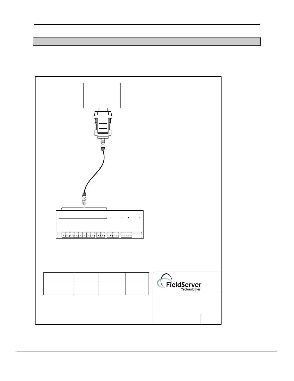
3. Hardware Connections
The FieldServer is connected to the ATMI ACM Panel as shown below.
Configure the ATMI ACM Panel according to manufacturer’s instructions
ATMI ACM PAN EL
COM 2
8917-02
RJ45 CAT 5 Cable
Connect to
RS232 port P1-P8
P1 P7 R1P2 R2
P3 P4 P5 P6 P8 N1 N2
Tx Rx Tx
P4P1RxP2 P3
TxRx Rx
RS232
Tx Rx Tx TxRx R x
P7P5 P6
P8 R1
Tx Rx Tx Rx Tx
R2 Net 1
TxRx RxTx Con
RS485
Net 2
Tx Rx Con
FieldServer
8917-02 WIRE LIST
FIELDSERVER
FUNCTION FROM TO COLOR
RX RJ45-01 DB9F -03 WHITE
GND RJ45-04 DB9F-05 GREEN
TX RJ45-08 DB9F-02 BLUE
Sys
Com
10 Base T
ETHERNET
Act
Run
Pwr
ATMI - ACM
CONNECTION DIAGRAM
BASE NAME:
FILE NAME: FS-T28700-64 .VSD
DATE: 1/21/02
BY: MN
(408)-262-2299
FieldServer Technologies 1991 Tarob Court Milpitas, California 95035 USA Web:www.fieldserver.com
Tel: (408) 262-2299 Fax: (408) 262-9042 Toll_Free: 888-509-1970 email: support@fieldserver.com
Page 5

FS-8700-64 ATMI ACM Page 4 of 22
4. Configuring the FieldServer as a ATMI ACM Client
The ATMI ACM driver is a passive client driver. This means that it processes unsolicited
incoming data. It cannot poll for data.
For a detailed discussion on FieldServer configuration, please refer to the instruction manual for
the FieldServer. The information that follows describes how to expand upon the factory defaults
provided in the configuration files included with the FieldServer (See “.csv” files on the driver
diskette).
This section documents and describes the parameters necessary for configuring the FieldServer
to communicate with a ATMI ACM Server.
The configuration file tells the FieldServer about its interfaces, and the routing of data required.
In order to enable the FieldServer for ATMI ACM communications, the driver independent
FieldServer buffers need to be declared in the “Data Arrays” section, the destination device
addresses need to be declared in the “Client Side Nodes” section, and the data required from
the servers needs to be mapped in the “Client Side Map Descriptors” section. Details on how to
do this can be found below.
Note that in the tables, * indicates an optional parameter, with the bold legal value being the
default.
4.1 Data Arrays
Section Title
Data_Arrays
Column Title Function Legal Values
Data_Array_Name Provide name for Data Array Up to 15 alphanumeric
characters
Data_Format Provide data format. Each data
array can only take on one format.
Data_Array_Length Number of Data Objects. Must be
larger than the data storage area
required for the data being placed
in this array.
Data from one ACM can be stored
in multiple data arrays. Position in
the array is dependent on gas
number area number. Further
details are provided in section 6.1
FLOAT, BIT, UInt16, SInt16,
Packed_Bit, Byte, INT32
Packed_Byte, Swapped_Byte
Gas values should only be
stored in INT32 or FLOAT
arrays.
1-10,000
Ensure that the arrays are 16 *
81 elements big.
FieldServer Technologies 1991 Tarob Court Milpitas, California 95035 USA Web:www.fieldserver.com
Tel: (408) 262-2299 Fax: (408) 262-9042 Toll_Free: 888-509-1970 email: support@fieldserver.com
Page 6

FS-8700-64 ATMI ACM Page 5 of 22
Example
// Data Arrays
//
Data_Arrays
Data_Array_Name, Data_Format, Data_Array_Length
DA_AI_01, UInt16, 200
DA_AO_01, UInt16, 200
DA_DI_01, Bit, 200
DA_DO_01, Bit, 200
4.2 Client Side Connections
Section Title
Connections
Column Title Function Legal Values
Port Specify which port the device is
connected to the FieldServer
Baud* Specify baud rate 110 – 115200, standard baud
Parity* Specify parity Even, Odd, None, Mark, Space
Data_Bits* Specify data bits 7, 8
Stop_Bits* Specify stop bits
Protocol Specify protocol used ATMI
Handshaking* Specify hardware handshaking RTS, RTS/CTS, None
Poll Delay* Time between internal polls 0-32000 seconds
Timeout Specifies the amount of time that
may pass between complete
data screens. If this time expires
a timeout error is produced but
the processing of data is not
affected. The port is not cleared
and gas data is not reset.
IC_Timeout This parameter is used in a way
that is different to most
FieldServer driver applications.
In this case of this driver it
specifies the maximum amount
of time that may pass between
the driver receiving an incoming
character. If the time is
exceeded then an error is
produced but note that the error
has no other effect on the driver.
The port is not cleared and gas
data is not reset.
P1-P8, R1-R2
rates only
1
default 1 second
This value should provide a
margin over the time configured
between samples in the
CONFIG.DAT profile of the
ACM unit.
This value (specified in
seconds) should be set allow a
margin between time stamp
messages from the ACM unit.
FieldServer Technologies 1991 Tarob Court Milpitas, California 95035 USA Web:www.fieldserver.com
Tel: (408) 262-2299 Fax: (408) 262-9042 Toll_Free: 888-509-1970 email: support@fieldserver.com
Page 7

FS-8700-64 ATMI ACM Page 6 of 22
Example
The following FieldServer settings are suitable for default ACM settings.
// Client Side Connections
Connections
Port, Baud, Parity, Protocol, Handshaking, Poll_Delay
P8, 9600, None, ATMI , None, 0.100s
4.3 Client Side Nodes
Section Title
Nodes
Column Title Function Legal Values
Node_Name Provide name for node Up to 32 alphanumeric
characters
Node_ID ACM units do not have a
node ID contained in the
serial data. This field s not
used in the ATMI ACM
driver.
Protocol Specify protocol used ATMI
Port Specify which port the
device is connected to the
FieldServer
Example
// Client Side Nodes
Nodes
Node_Name, Protocol, Port
ACM-1 , ATMI , P8
P1-P8, R1-R2
4.4 Client Side Map Descriptors
4.4.1 FieldServer Specific Map Descriptor Parameters
Column Title Function Legal Values
Map_Descriptor_Name Name of this Map Descriptor Up to 32 alphanumeric
characters
Data_Array_Name Name of Data Array where
data is to be stored in the
FieldServer
Data_Array_Location Starting location in Data
Array
Function Function of Client Map
Descriptor
FieldServer Technologies 1991 Tarob Court Milpitas, California 95035 USA Web:www.fieldserver.com
Tel: (408) 262-2299 Fax: (408) 262-9042 Toll_Free: 888-509-1970 email: support@fieldserver.com
One of the Data Array
names from “Data Array”
section above
0 to maximum specified in
“Data Array” section above
PASSIVE
Page 8

FS-8700-64 ATMI ACM Page 7 of 22
4.4.2 Driver Specific Map Descriptor Parameters
Column Title Function Legal Values
Node_Name Name of Node to fetch data
from
One of the node names
specified in “Client Node
Descriptor” above
Data_Array_Offset Position in the data array to
0, 1 , 2 , 3
which data should start being
written.
Length Length of Map Descriptor. The
1 – 1280
length is required to help the
driver validate the CSV file.
Set the length to a multiple of
16. The multiple should be the
maximum area number.
Address Starting address of read block 0
Driver specific keywords
The following parameters apply only to the AMI ACM driver.
ATMI_Data* Used to specify which
component of the gas data
structure to store.
You will need one map
descriptor for each
component that you are
interested in storing.
See section 6.9 for more
info.
Slot-alarm,
Slot-warning,
Slot-combo
Slot-values
Port-alarm,
Port-warning,
Port-combo
Gas-value, (== Port-values)
Current-Port
Current-Slot
Malfunctions
4.4.3 Timing Parameters
Column Title Function Legal Values
Scan_Interval Rate at which data is polled >0.1s
FieldServer Technologies 1991 Tarob Court Milpitas, California 95035 USA Web:www.fieldserver.com
Tel: (408) 262-2299 Fax: (408) 262-9042 Toll_Free: 888-509-1970 email: support@fieldserver.com
Page 9

FS-8700-64 ATMI ACM Page 8 of 22
f
p
H
A
4.4.4 Map Descriptor Example 1- Gas Values, Alarms & Warnings for all slots/ports.
This example illustrates the map descriptors required to complete store ACM data for 80 areas. Each map descriptor tells the ATMI ACM driver
where to store each component of ACM data. The gas number & area number determine the position in the array. Read section 6.1 for more
information
Map_blocks
Map_block_Name, Data_Array_Name, Data_Array_Offset, Function, node_name, Address, Length, protocol, atmi_data
MAP1 , DATA1_1 , 0 , passive , ACM1 , 0, 1280 , ATMI , port-values
MAP2 , DATA1_2 , 0 , passive , ACM1 , 0, 1280 , ATMI , port-alarm
MAP3 , DATA1_3 , 0 , passive , ACM1 , 0, 1280 , ATMI , port-warning
MAP4 , DATA1_4 , 0 , passive , ACM1 , 0, 1280 , ATMI , slot-alarm
MAP5 , DATA1_5 , 0 , passive , ACM1 , 0, 1280 , ATMI , slot-warning
MAP6 , DATA1_6 , 0 , passive , ACM1 , 0, 1280 , ATMI , slot-combo
MAP7 , DATA1_7 , 0 , passive , ACM1 , 0, 1280 , ATMI , port-combo
MAP8 , DATA1_8 , 0 , passive , ACM1 , 0, 1280 , ATMI , slot-values
These keywords tell the driver which component of the
A different array is
used for each
atmi_data
component being
stored.
The gas value array
would typically be
an array of FLOATs
and the alarms and
This is a passive
client driver so the
unction must be
assive.
This node name will
connect this map
descriptor to a node
which in turn is
connected to a port.
ence the map
descriptor is
connected to a port.
CM data should be
Stored using each map descriptor.
If you were only interested in the current value then
you would only use one map descriptor and set the
atmi_data parameter equal to gas-value
The “…-combo” types store a 1 for an alarm OR
warning and a zero when neither conditionis present.
warnings could be
any data type
including bit arrays
.
FieldServer Technologies 1991 Tarob Court Milpitas, California 95035 USA Web:www.fieldserver.com
Tel: (408) 262-2299 Fax: (408) 262-9042 Toll_Free: 888-509-1970 email: support@fieldserver.com
Page 10

FS-8700-64 ATMI ACM Page 9 of 22
N
4.4.5 Map Descriptor Example2 – Gas values for the current (most recent) port sample.
This example illustrates a map descriptors used to store the data from the most recent port sample. The map descriptor stores the following
information :-
1. Port Number
2. Up to 16 gas values (The gas name is not provided) The position in the array is based on the Gas Number.
For example. A port may sample two gasses. The first is Gas #4 and the second may be Gas #2, The driver stores the value of Gas#4 in
array location 4 and stores the value of Gas#2 at array location 2.
The following additional information may also be stored if the DA_Bit_Name & DA_Byte_Name parameters are specified.
3. A bit indicating the number of the port
4. The Alarm/Warning States for each gas
Map_blocks
Map_block_Name, Data_Array_Name, Data_Array_Offset, Function, node_name, protocol, timeout, atmi_data , da_bit_name, da_byte_name
Current_Port_MD, DA_CURR_PORT, 0 , passive , ACM1 , ATMI ,120.0s , current-port, DA_PORT , DA_PORT_ALA
The current port
number and up to 16
gas values are stored
in this data array.
st
The 1
element
stored is the port
number. The next
16 values stored are
the gas values
(multiplied by 100).
The location is
based on the Gas
umber and not the
row number.
This keyword tells
the driver to use this
map descriptor to
store the current
port’s sample data..
If x is the number of the current
port (port most recently
sampled) then the data array
position corresponding to x is
set to 1 and all other elements
are set to zero.
E.g. If Port 1 is the current port
then the 2
nd
element of the
array (index=1) is set non-zero.
The array can be any data
format.
If the DA_Bit_Name parameter
is omitted then this data is not
Alarm / Warning Status for each gas is
indicated in this array.
If gas x is in alarm then x is used as the
index into the array. E.g. If Gas #1 is in
alarm then the 2
(index=1) is set non-zero.
The value of each element indicates
alarm/warning. If the Value is 1 then the
gas in alarm. If the value is two then the
gas is at a warning level.
The array format should be capable of
storing a value. If a Bit/Packed_Bit format
is used then you will not be able to
distinguish between an alarm/warning.
If the DA_Byte_Name parameter is
omitted then this data is not stored.
FieldServer Technologies 1991 Tarob Court Milpitas, California 95035 USA Web:www.fieldserver.com
Tel: (408) 262-2299 Fax: (408) 262-9042 Toll_Free: 888-509-1970 email: support@fieldserver.com
nd
element of the array
Page 11

FS-8700-64 ATMI ACM Page 10 of 22
4.4.6 Map Descriptor Example3 – Storing Malfunction Data
This example illustrates a map descriptor used to store malfunction data reported by the ACM unit. When a malfunction is cleared then 100
elements of the array are set to zero. When a Malfunction is present the 1
contains the minor type and element x (x=major*10+minor) is set to a value of 1. Additional information is provided in section 6.7
Map_blocks
Map_block_Name, Data_Array_Name, Data_Array_Offset, Function, node_name, timeout, atmi_data , length
Malfucntion_MD , DA_MALFNS , 0 , passive , ACM1 , 120.0s , malfunctions, 100
st
element contains the malfunction’s major type, the 2nd element
This keyword tells
One hundred
elements of this
data array are used
to store
malfunction data.
the driver to use
this map
descriptor to
malfunction data.
One map
descriptor is
required per node.
FieldServer Technologies 1991 Tarob Court Milpitas, California 95035 USA Web:www.fieldserver.com
Tel: (408) 262-2299 Fax: (408) 262-9042 Toll_Free: 888-509-1970 email: support@fieldserver.com
Page 12

FS-8700-64 ATMI ACM Page 11 of 22
N
4.4.7 Map Descriptor Example4 – Gas values for the current (most recent) slot sample.
This example illustrates a map descriptors used to store the data from the most recent slot sample. The map descriptor stores the following
information :-
5. Slot Number
6. Up to 16 gas values (The gas name is not provided) The position in the array is based on the Gas Number.
For example. A slot may sample two gasses. The first is Gas #4 and the second may be Gas #2, The driver stores the value of Gas#4 in
array location 4 and stores the value of Gas#2 at array location 2.
The following additional information may also be stored if the DA_Bit_Name & DA_Byte_Name parameters are specified.
7. A bit indicating the number of the slot
8. The Alarm/Warning States for each gas
Map_blocks
Map_block_Name, Data_Array_Name, Data_Array_Offset, Function, node_name, protocol, timeout, atmi_data , da_bit_name, da_byte_name
Current_Port_MD, DA_CURR_SLOT, 0 , passive , ACM1 , ATMI ,120.0s , current-slot, DA_SLOT , DA_SLOT_ALA
The current slot
number and up to 16
gas values are stored
in this data array.
st
The 1
element
stored is the slot
number. The next
16 values stored are
the gas values
(multiplied by 100).
The location is
based on the Gas
umber and not the
row number.
FieldServer Technologies 1991 Tarob Court Milpitas, California 95035 USA Web:www.fieldserver.com
Tel: (408) 262-2299 Fax: (408) 262-9042 Toll_Free: 888-509-1970 email: support@fieldserver.com
This keyword tells
the driver to use this
map descriptor to
store the current
slot’s sample data..
If x is the number of the current
slot (slot most recently
sampled) then the data array
position corresponding to x is
set to 1 and all other elements
are set to zero.
E.g. If Slot 1 is the current slot
then the 2
nd
element of the
array (index=1) is set non-zero.
The array can be any data
format.
If the DA_Bit_Name parameter
is omitted then this data is not
Alarm / Warning Status for each gas is
indicated in this array.
If gas x is in alarm then x is used as the
index into the array. E.g. If Gas #1 is in
alarm then the 2
nd
element of the array
(index=1) is set non-zero.
The value of each element indicates
alarm/warning. If the Value is 1 then the
gas in alarm. If the value is two then the
gas is at a warning level.
The array format should be capable of
storing a value. If a Bit/Packed_Bit format
is used then you will not be able to
distinguish between an alarm/warning.
If the DA_Byte_Name parameter is
omitted then this data is not stored.
Page 13

FS-8700-64 ATMI ACM Page 12 of 22
5. Configuring the FieldServer as a ATMI ACM Server
The ATMI ACM driver cannot be used as a server.
6. Driver Notes
6.1 Data position in the Data Arrays
To understand how the driver stores data for the current port, read the notes provided with mapdescriptor example 2 as the following notes do not apply.
To understand how the driver stores data for malfunctions, read the notes provided with mapdescriptor example 3 as the following notes do not apply.
For each component stored the values are stored as a one-dimensional array. Data storage is
zero referenced. This means that the first area or first gas is stored in the first location, which
has an index of zero. To find the element of interest use the following formula.
Port Alarm / Warnings / Gas Values Data Array locations
Port_Index = (Gas_number-1) + 16 * ( Area_Number – 1 )
‘Area’ and ‘Port’ are synonyms.
Example. If you wish to know the Data Array index for gas #7 of area 11
Index = (7-1) + 16 * ( 10 – 1 ) = 166
Example. If you wish to know the Data Array index for the 7
11
Index = 7 + 16 * ( 10 – 1 ) = 167.
Slot Alarm / Warnings / Values Data Array locations
Slot_Index = (Gas_number-1) + 16 * ( Slot_Number – 1 )
Example. The Data Array location for gas #12 of Slot 4
Index = (12-1) + ( 4 – 1 ) * 16 = 59
th
gas of area
FieldServer Technologies 1991 Tarob Court Milpitas, California 95035 USA Web:www.fieldserver.com
Tel: (408) 262-2299 Fax: (408) 262-9042 Toll_Free: 888-509-1970 email: support@fieldserver.com
Page 14

FS-8700-64 ATMI ACM Page 13 of 22
6.2 Driver Stats
The ATMI ACM Driver counts all incoming bytes as the ‘PLC Byte Received’ statistic. This can
be viewed on the connection detail and overview screen. Typically this count will increase by
approx 2500 bytes per full screen of area data.
IN addition the driver reports one count of ‘PLC READ MSG RECD’ statistic for each map
descriptor used to store information from a complete message. Typically this count will increase
by 5 if you are storing l slot & port alarms & warnings and the gas value.
If a complete message is received but no map descriptor is found to store any of the data the
data then the MSG IGNORED statistic will be incremented by one.
6.3 Exposing Driver Stats
IN addition to the normal FieldServer statistics this driver can expose some statistics and
diagnotic information in a data rray so that it may be read or reset by a remote device.
A special map descriptor is required. The driver recognizes the map descriptor by its name
which must be "ATMI-stats" .
The following example shows how this special map descriptor can be configured.
Nodes
Node_name, Protocol
null_node, ATMI
Data_Arrays
Data_Array_Name , Data_Format, Data_Array_Length
STAT-DATA , UINT32 , 400
Map_blocks
Map_block_Name, Data_Array_Name, Node_name
ATMI-stats , STAT_DATA , null_node
When the driver sees this map descriptor it uses the data array STAT_DATA (in this example)
to store driver specific statistics. Only one of these map descriptors may be specified per
FieldServer.
The array position is dependent on the port number. The offset is calculated by multiply the port
number by 30. Thus port 2 data will start at element 60.
FieldServer Technologies 1991 Tarob Court Milpitas, California 95035 USA Web:www.fieldserver.com
Tel: (408) 262-2299 Fax: (408) 262-9042 Toll_Free: 888-509-1970 email: support@fieldserver.com
Page 15

FS-8700-64 ATMI ACM Page 14 of 22
The driver stores the following data.
Array
Element
(offset
dependent
on port
number)
Contents
0 Not Used
1 ATMI_STAT_SCAN1 FieldServer Tech Support diagnostic.
2
FieldServer Tech Support diagnostic.
Screen decoding abandoned because
the area number was unintelligible (>
ATMI_STAT_DECODE1
3
ATMI_STAT_FINIS
4
80)
Driver has found an end-of-screen
identifier.
FieldServer Tech Support diagnostic.
The line number was unintelligible ( >
ATMI_STAT_COLLECT1
5
25 ).
FieldServer Tech Support diagnostic.
The collection function returned an
ATMI_STAT_COLLECT2
6
error. Row or Column were inconsistent.
FieldServer Tech Support diagnostic. A
start-of-screen identifier was found
ATMI_STAT_COLLECT3
7
ATMI_STAT_ERRORLIGHT
8
ATMI_STAT_START
9
ATMI_STAT_LF
10
before whilst processing screen data.
Equivalent to the error light on the ATMI
ZD80 processor.
A start of screen identifier has been
found.
A new line of screen data has been
identified.
FieldServer Tech Support diagnostic.
The collection function returned an
ATMI_STAT_ERRORLIGHT1
11
error. Row was inconsistent.
FieldServer Tech Support diagnostic.
The collection function returned an
ATMI_STAT_ERRORLIGHT2
12
error. Column was inconsistent.
A time greater than the port timeout has
elapsed since the last complete screen
ATMI_STAT_TIMEOUT
13
full of data.
A time greater than the port’s inter
character timeout (ic_timeout) has
passed since the driver last received a
ATMI_STAT_ICTIMEOUT
14
ATMI_STAT_BYTECOUNT
15
ATMI_STAT_STREAMING
16
new character from the ACM unit.
The number of ACM data byte
processed
The number of streaming (buffer
overflow) errors.
When processing the most recent
message, at least one map descriptor
ATMI_STAT_STORE_LASTMAPDESCP
was found with which to store data.
FieldServer Technologies 1991 Tarob Court Milpitas, California 95035 USA Web:www.fieldserver.com
Tel: (408) 262-2299 Fax: (408) 262-9042 Toll_Free: 888-509-1970 email: support@fieldserver.com
Page 16

FS-8700-64 ATMI ACM Page 15 of 22
17
ATMI_STAT_STORE_NO_MAP
18
ATMI_STAT_STORE
19
ATMI_STAT_STORE_NONZERO
20
ATMI_STAT_MALFN_BAD_MAJOR
21
ATMI_STAT_MALFN_BAD_MINOR
22
ATMI_STAT_MALFN_STREAMING
6.4 Driver Error Messages
When processing the most recent
message, no map descriptors were
found to tell the driver how to store the
incoming data.
Increment’s once for each time data is
stored. Ie will increase by 5 for one
screen full of data stored using 5 map
descriptors.
Will increase by one for each screen full
of data processed in which at least one
gas value was non-zero.
Count of the number of times that a
malfunction’s major type could not be
recognized.
Count of the number of times that a
malfunction’s minor type could not be
recognized.
Count of the number of times that the
buffer overflowed when analyzing
malfunction data. Each time this
happens the malfunction is not stored.
The following error messages should be reported to FieldServer Technologies.
ATMI:#4 Error. atmi_chan_init() Init with null chan.
The following errors indicate a driver, connection or remote device problem if they occur
frequently.
ATMI:#8 Error. Discard because area=%d max=%d
Incoming data has been discarded because the driver could not resolve a valid area number.
The following error messages or warning arise from problems that can normally be
resolved by users without support from FieldServer Technologies.
ATMI:#7 Error. No read/writes permitted. Mapdesc=<%s>
Edit the CSV file. Change the map descriptor function to passive. Reset the FieldServer.
ATMI:#1 FYI. Some data is being abandoned. Mapdesc too short. <%s>
Edit the CSV file. Increase the map descriptor’s length to allow the driver to process the
maximum data area. Not each data area requires 16 storage elements. Reset the FieldServer.
This message is only printed once even if the error occurs more than once.
ATMI:#2 FYI. Some data is being abandoned. Array too short. <%s>
Edit the CSV file. Increase the Map Descriptor’s data array length. Reset the FieldServer. This
message is only printed once even if the error occurs more than once.
FieldServer Technologies 1991 Tarob Court Milpitas, California 95035 USA Web:www.fieldserver.com
Tel: (408) 262-2299 Fax: (408) 262-9042 Toll_Free: 888-509-1970 email: support@fieldserver.com
Page 17

FS-8700-64 ATMI ACM Page 16 of 22
ATMI:#3 Error. Incoming data on port=%d is being abandoned. MapDesc rqd.
No map descriptors were found on the indicated port with which the driver could store the
incoming data. Change the CSV file and reset the FieldServer. This message is only printed
once even if the error occurs more than once.
ATMI:#6 FYI. The mapDesc called <%s> is too short.
Edit the CSV file. Increase the length of the map desc and reset the FieldServer.
ATMI:#5 FYI. You could have used a mapDesc called <%s> to expose diagnostic info.
No action I s required. Read section 6.3 for more information..
*ATMI:#9 Err. Mapdesc=<%s> data array=<%s> too short
The data array associated with the map descriptor being used to store ‘current port‘ data is too
short. Increase the length of the data array (not the length of the map descriptor) to at least 17.
For malfunction map descriptors set the length to at least 100. Edit the CSV file, make the
change and then reset the bridge.
*ATMI:#10 Err. Mapdesc=<%s> data array=<%s> too short
The data array defined by the DA_Bit_Name parameter associated with the map descriptor
being used to store ‘current port‘ data is too short. Increase the length of the data array (not the
length of the map descriptor) to at least 90. Edit the CSV file, make the change and then reset
the bridge.
*ATMI:#11 Err. Mapdesc=<%s> data array=<%s> too short
The data array defined by the DA_Byte_Name parameter associated with the map descriptor
being used to store ‘current port‘ data is too short. Increase the length of the data array (not the
length of the map descriptor) to at least 90. Edit the CSV file, make the change and then reset
the bridge.
2Mapdesc=<%s> Gas#=%d. Too big.The driver is trying to store the the current port’s gas data.
A Gas number larger than 16 has been found. It cannot be stored and has been discarded.
Your ACM may need re-configuring. Changing the driver configuration will not correct this
problem. Report this error to ATMI.*These messages are produce once only and then
suppressed so that they do not fill the error log every by being re-printed every time a new
message is processed. A consequence of this, is that, if the error occurs more than once in a
configuration, the second and subsequent occurrences will not be revealed until the first has
been corrected.
*ATMI:#13 Error. Illegal Map Descriptor length - defaulting to 1
FieldServer Technologies 1991 Tarob Court Milpitas, California 95035 USA Web:www.fieldserver.com
Tel: (408) 262-2299 Fax: (408) 262-9042 Toll_Free: 888-509-1970 email: support@fieldserver.com
Page 18

FS-8700-64 ATMI ACM Page 17 of 22
6.5 Timeouts
See section 4.2 for information on how timeouts should be specified.
Occasional timeouts may be expected when there are noisy messages or if the ACM device has
been locked. Timeouts do not stop the driver processing the next valid screen of data.
6.6 Demand & Lock Scan
The driver can process data from demand and locked scans. Incoming data is processed in the
same way as normal scans and stored using the same map descriptors.
6.7 Malfunctions
The driver can process malfunctions reported by the ACM unit.
When a malfunction is cleared then the driver sets all (1
elements to zero A malfunction is considered cleared when a normal scan is processed.
When a malfunction is recognized the driver stores data in the following locations.
1
2
st
Element : Major type of the malfunction ( as a number )
nd
Element : Minor type of the malfunction. (as a number )
And
Element x : Value set to 1.
X = major * 10 + minor
This additional data element is provided so that relays / indicating lamps in a downstream
device can be set without additional logic.
The driver uses the keyword ‘MALFUNCTION’ to recognize ACM malfunctions. If the ACM
firmware is changed and this keyword is no longer produced then the driver will no longer
recognize malfunctions.
If the driver recognizes that there is a malfunction but cannot interpret the malfunction type then
the major and/or minor types are set to a value of 99 and element x is not set at all.
The table below shows malfunction’s major and minor types.
st
100) of the malfunction data array
FieldServer Technologies 1991 Tarob Court Milpitas, California 95035 USA Web:www.fieldserver.com
Tel: (408) 262-2299 Fax: (408) 262-9042 Toll_Free: 888-509-1970 email: support@fieldserver.com
Page 19

FS-8700-64 ATMI ACM Page 18 of 22
Malfunction Major Type Mafunction Minor Type
1. INADEQUATE BYPASS FLOW 0.
2. EMERGENCY SWITCH
CLOSURE
1.TEMP_LOW
2. TEMP_HIGH
3. LOSS_OF_NH3_FLOW
3. FAILED LEAK CHECK 0.
4. DSP FAILURE in module 0.
5. FAILURE to get interferogram
1. Bench timeout
2. Bench short scan
3. Zero ZPD value or address
4. Bench reports Bad Scan
5. Bench DREQ stuck TRUE
6. Energy (ZPD) address out of
range
7. energy (ZPD) value too high
8. energy (ZPD) value too low
9. DSP reports bad scan
6.8 Gas Values & Scaling
The driver stores all gas values after multiplying them by 100. This allows the driver to store
values in arrays with formats other than floats without losing the precision provided by the ACM
unit. This is done because some downstream devices’ and protocols cannot handle floating
point numbers. This may not suite you in which case you will need to use scaling.
These parameter keywords should be added to each CSV Map Descriptor definition.
…..Data_Array_Low_Scale, Data_Array_High_Scale, Device_Low_Scale,
Device_High_Scale…….
To store the actual values reported by the ACM unit you should use the following values :
…..Data_Array_Low_Scale, Data_Array_High_Scale, Device_Low_Scale,
Device_High_Scale…….
…..0 , 1 , 0 , 100…..
6.9 Alarms and/or Warnings
The following list are valid entries in specifying the ATMI_Data parameter in the csv file.
Slot-alarm,
Slot-warning,
Slot-combo
Port-alarm,
Port-warning,
Port-combo
FieldServer Technologies 1991 Tarob Court Milpitas, California 95035 USA Web:www.fieldserver.com
Tel: (408) 262-2299 Fax: (408) 262-9042 Toll_Free: 888-509-1970 email: support@fieldserver.com
Page 20

FS-8700-64 ATMI ACM Page 19 of 22
When you use a “…-alarm” keyword then the driver stores a 1 when the gas is in an alarm
condition and a zero when it is not in alarm condition. This means a zero is stored even if the
gas in a warning condition.
When you use a “…-warning” keyword then the driver stores a 1 when the gas is in a warning
condition and a zero when it is not in warning condition. This means a zero is stored even if the
gas in an alarm condition as well as when the gas is in a normal condition.
When you use a “….-combo” keyword then the driver stores a 1 whether the gas is in an alarm
OR warning condition and the driver stores a zero when the gas is in neither an an alarm or
warning state.
6.10 Current Slot
Current slot information is the same as current port information. On a Normal Scan, a single
slot is referenced. The gas values/warnings/alarms will be stored to the current slot data arrays
every time slot information is stored. Note, this only occurs once during any Normal Slot Scan
image.
6.11 Composite Validation Scan vs Normal Slot Scan
On a Normal Slot Scan Image, gas data is stored to the "slot" value/warning/alarm data arrays
and the "port" value/warning/alarm data arrays. If more than one port (area) is referenced in the
image, then the same value/warning/alarm gas data is copied to each section of the area "data
array". For example, if Areas 2 and 39 were referenced, then the gas data values and
warning/alarm status would be copied twice to the data array offset for Area 2 and the offset for
Area 39.
On a Composite Validation Image, only one area (port) should be referenced. The gas
values/warnings/alarms for the particular area referenced will be updated. As well the current
port data values will also be updated. Note, on Composite Validation Images, slot information is
not updated.
FieldServer Technologies 1991 Tarob Court Milpitas, California 95035 USA Web:www.fieldserver.com
Tel: (408) 262-2299 Fax: (408) 262-9042 Toll_Free: 888-509-1970 email: support@fieldserver.com
Page 21

FS-8700-64 ATMI ACM Page 20 of 22
7. Revision Control
Date Rev Resp Description
1.01a Rev1 PMC This revision and all previous revisions did not have a
revision control section.
1.01a Rev
2
1.01b Rev
0
101c Rev0 Section 4.4.5 Corrections and additional notes to
102a Rev0 Section 4.4.2 New valid keywords for ATMI_Data
PMC This issue of the manual corresponds to the release of
driver version 1.01a in which functionality was added to
store the current port sample’s data separately.
The following sections of this manual have been
amended.
• Section 1. Driver previously described as
client /server.
• Section 4.4.2 New keyword
• Section 4.4.4 Title Changed
• Section 4.4.5 New example
• Section 6.1 Amended
• Section 6.4 Error messages 9,10,11 added.
• Section 4.4.2 New keyword
• Section 4.4.6 New example
• Section 6.1 Amended
• Section 6.3 New stats 20-22
• Section 6.4 Amended notes for msg #9.
• Section 6.7 New Section
describe storage of gas values
based on sample number.
Section 6.8 New notes on scaling. Prior to revision
1.01c of the driver this feature did not operate and all
values were stored 100 times too large.
parameter. “port-combo” and “slotcombo”
Section 4.4.4 Modified example to illustrate use
of “…-combo” keywords.
Section 6.9 New section on ATMI_Data parameter.
FieldServer Technologies 1991 Tarob Court Milpitas, California 95035 USA Web:www.fieldserver.com
Tel: (408) 262-2299 Fax: (408) 262-9042 Toll_Free: 888-509-1970 email: support@fieldserver.com
Page 22

FS-8700-64 ATMI ACM Page 21 of 22
10Feb03 1.03a Rev 0 PMC Section 4.4.2
New keywords. Added slot-values and portvalues (as synonym for gas-values)
Section 6.1
Calculation of Data Array offsets
Section 7
Consolidated the revision information into a
table.
TOC
Updated Table of Contents
9Apr03 1.04aRev 0 DNC Section 4.4.2
Added new key word "Current-Slot"
Section 4.4.7
Added Current-Slot example
Section 6.10
Added section discussing current slot
information
Section 6.11
Added section discussing Composite
Validation Scan handling, and Normal Scan
Driver Enhancement:
1. On normal scan, driver will save
values/warns/alarms for up to 4 ports per screen
2. On a decomposed screens port data will be updated
for port that was referenced, no changed to slot info
3. Current slot info implemented. Data references last
update to slot info.
10Apr03 1.04aRev1 DNC -updated error numbers
21July03 1.04Rev1 JDM Releasing
FieldServer Technologies 1991 Tarob Court Milpitas, California 95035 USA Web:www.fieldserver.com
Tel: (408) 262-2299 Fax: (408) 262-9042 Toll_Free: 888-509-1970 email: support@fieldserver.com
 Loading...