

Page 1
Driver Version:
1.03
Document Revision:
3
APPLICABILITY & EFFECTIVITY
Effective for all systems manufactured after April 2012
Driver Manual
(Supplement to the FieldServer Instruction Manual)
FS-8700-43 Vesda
A Sierra Monitor Company
Page 2

FS-8700-43 VESDA Driver Manual Table of Contents
TABLE OF CONTENTS
1 VESDA Description ......................................................................................................................................... 4
2 Driver Scope of Supply ................................................................................................................................... 4
2.1 Supplied by FieldServer Technologies for this Driver ................................................................................... 4
2.2 Provided by Supplier of 3rd Party Technology .............................................................................................. 4
3 Hardware Connections ................................................................................................................................... 5
4 Data Array Parameters ................................................................................................................................... 6
5 Configuring the FieldServer as a VESDA Client................................................................................................ 7
5.1 Client Side Connection Parameters .............................................................................................................. 7
5.2 Client Side Node Parameters ....................................................................................................................... 8
5.3 Client Side Map Descriptor Parameters ....................................................................................................... 8
5.3.1 FieldServer Related Map Descriptor Parameters ..................................................................................... 8
5.3.2 Driver Related Map Descriptor Parameters ............................................................................................. 9
5.3.3 Map Descriptor Example ........................................................................................................................ 10
Appendix A. Useful Features ................................................................................................................................ 11
Appendix A.1. VESDA mapping format for Command 1 (Set Operation) ................................................................ 11
Appendix A.1.1. Data Arrays ............................................................................................................................ 11
Appendix A.1.2. Client Side Map Descriptors ................................................................................................... 11
Appendix A.1.3. Example .................................................................................................................................. 11
Appendix A.2. VESDA mapping format for Command 4 (Zone Update) .................................................................. 12
Appendix A.2.1. Data Arrays ............................................................................................................................ 12
Appendix A.2.2. Client Side Map Descriptors ................................................................................................... 12
Appendix A.2.3. Data Block Description ........................................................................................................... 12
Appendix A.3. VESDA mapping format for Command 6 (Remote Input) ................................................................ 14
Appendix A.3.1. Data Array .............................................................................................................................. 14
Appendix A.3.2. Client Map Descriptors ........................................................................................................... 14
Appendix A.3.3. Data Block Description ........................................................................................................... 14
Appendix A.4. VESDA mapping format for command 10 (Update Display Status) .................................................. 16
Appendix A.4.1. Data Arrays 1 ......................................................................................................................... 16
Appendix A.4.2. Data Arrays 2 ......................................................................................................................... 16
Appendix A.4.3. Client Side Map Descriptors ................................................................................................... 16
Appendix A.4.4. Data Block 1 Description ........................................................................................................ 17
Appendix A.4.5. Data Block 2 Description ........................................................................................................ 17
Appendix A.5. VESDA mapping format for command 12 (Current Fault Status) ..................................................... 19
Appendix A.5.1. Data Arrays ............................................................................................................................ 19
Appendix A.5.2. Client Side Map Descriptors ................................................................................................... 19
Appendix A.5.3. Data Block Description ........................................................................................................... 19
Appendix A.6. VESDA mapping format for command 16 (Update Airflow Status) .................................................. 21
Appendix A.6.1. Data Arrays 1 ......................................................................................................................... 21
Appendix A.6.2. Data Arrays 2 ......................................................................................................................... 21
Appendix A.6.3. Client Side Map Descriptors ................................................................................................... 21
Appendix A.6.4. Data Block 1 Description ........................................................................................................ 22
Appendix A.6.5. Data Block 2 Description ........................................................................................................ 22
Appendix A.7. VESDA mapping format for command 27 (Get Overall Smoke Thresholds) .................................... 24
FieldServer Technologies 1991 Tarob Court Milpitas, California 95035 USA Web: www.fieldserver.com
Tel: (408) 262 2299 Fax: (408) 262 2269 Toll Free: (888) 509 1970 email: support@fieldserver.com
Page 3

FS-8700-43 VESDA Driver Manual Table of Contents
Appendix A.7.1. Data Arrays ............................................................................................................................ 24
Appendix A.7.2. Client Side Map Descriptors ................................................................................................... 24
Appendix A.8. VESDA mapping format for command 29 (Set Smoke Thresholds).................................................. 26
Appendix A.8.1. Data Arrays ............................................................................................................................ 26
Appendix A.8.2. Client Side Map Descriptors ................................................................................................... 26
Appendix A.8.3. Data Block Description ........................................................................................................... 26
Appendix B. Troubleshooting ............................................................................................................................... 28
Appendix B.1. VESDA Panel start-up delay. ............................................................................................................. 28
Appendix B.2. Reading Smoke Levels on the VESDA Panels .................................................................................... 28
FieldServer Technologies 1991 Tarob Court Milpitas, California 95035 USA Web: www.fieldserver.com
Tel: (408) 262 2299 Fax: (408) 262 2269 Toll Free: (888) 509 1970 email: support@fieldserver.com
Page 4
FS-8700-43 VESDA Driver Manual Page 4 of 28
Fieldserver Mode
Nodes
Comments
Client
1
1 HLI can be connected to each RS232 port
Server
nil
Not applicable
FieldServer Technologies PART #
Description
FS-8915-10
UTP cable (7 foot) for RS-232 use
FS-8917-03
RJ45 to DB9M connector adapter
Part #
Description
VESDA VLP
VESDA HLI
DB15 Standard VGA Extension Cable
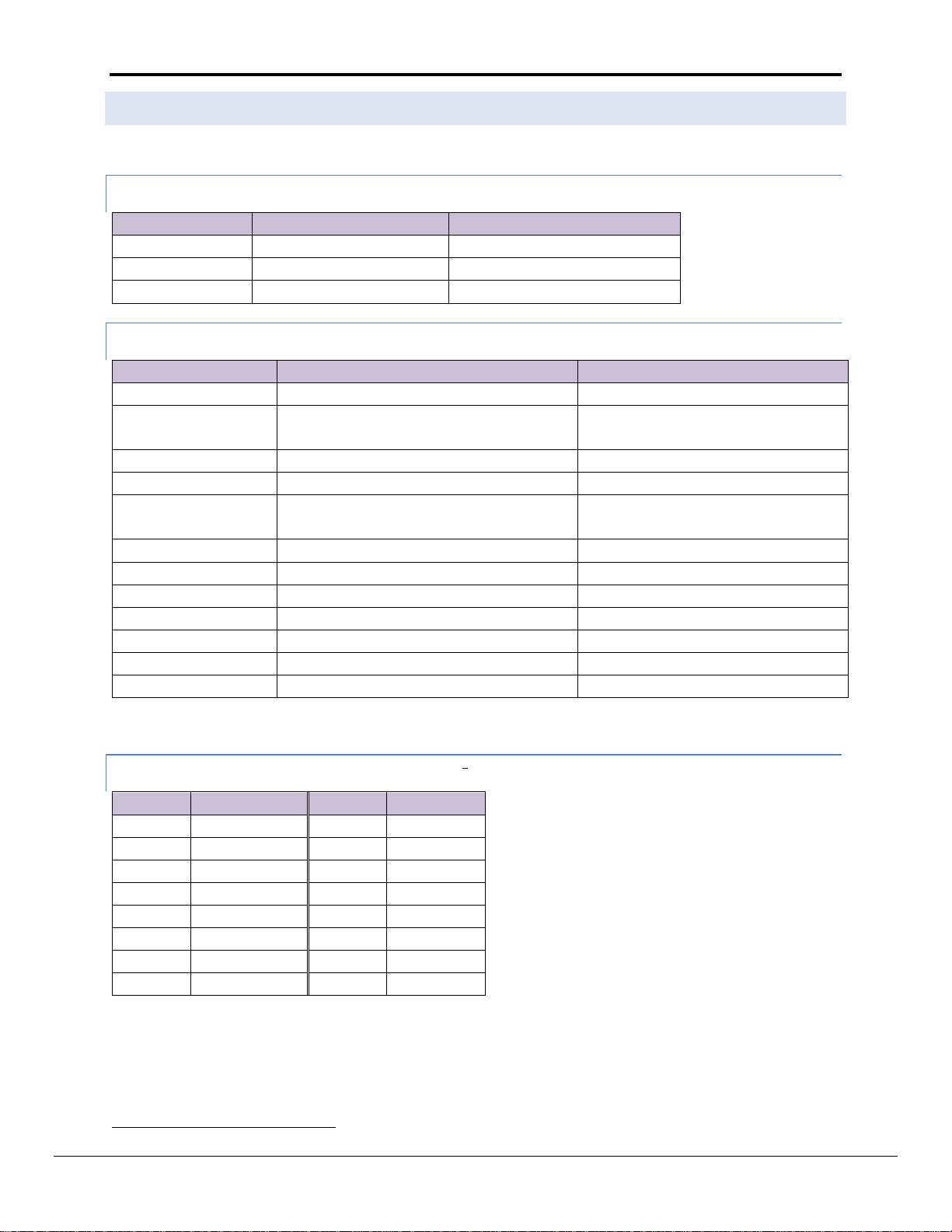
1 VESDA D E S C RIPTION
The VESDA driver allows the FieldServer to read data from VESDA LaserPLUS controllers (FAS or FD type) via the
VESDA High Level Interface (HLI) communications module, using RS-232. The FieldServer can be used only as a
Client with this driver, and operates in the HLI Master/Slave mode.
The information that follows describes how to expand upon the factory defaults provided in the configuration files
included with the FieldServer.
2 DRIVER S C OPE OF SUPP LY
2.1 Supplied by Fiel dServer Tec hno l o gies for this D r i v er
2.2 Provided by S u p plier of 3
rd
Party Techno l o gy
FieldServer Technologies 1991 Tarob Court Milpitas, California 95035 USA Web: www.fieldserver.com
Tel: (408) 262 2299 Fax: (408) 262 2269 Toll Free: (888) 509 1970 email: support@fieldserver.com
Page 5

FS-8700-43 VESDA Driver Manual Page 5 of 28
VESDA HLI
FieldServer Part #
8915-10
UTP cable
FS-8917-
03
FS-8917-03
RJ45 to DB9M Connector
DB15 Standard VGA Extension
Cable
FieldServer
P1
18
VESDA VLP
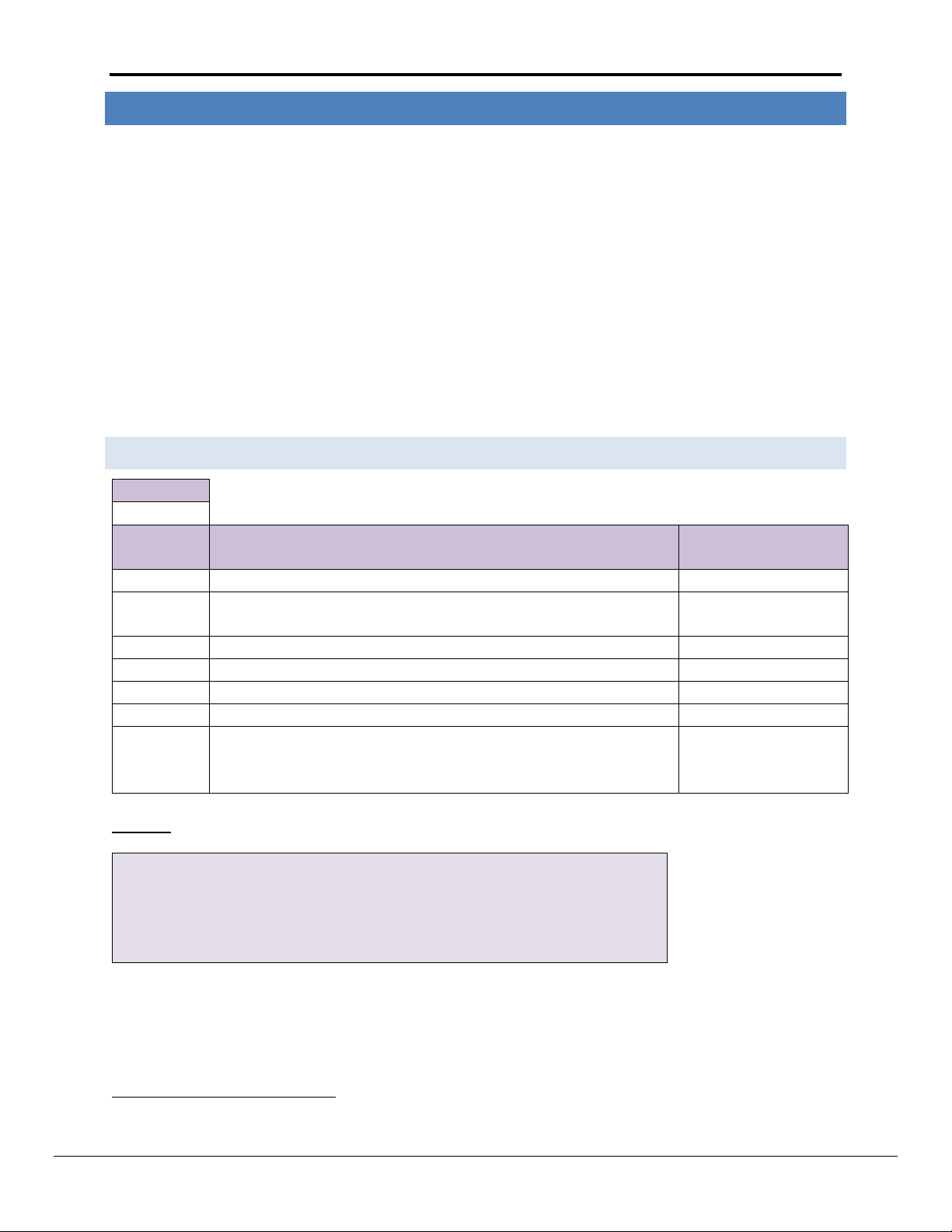
FS Function
RJ45 Pin#
DB9M Pin#
Color
RX 1 2
White
CTS 2 8
Brown
DSR 3 6
Yellow
GND
4 5 Green
DTR 6 4
Black
RTS 7 7
Orange
TX 8 3
Blue
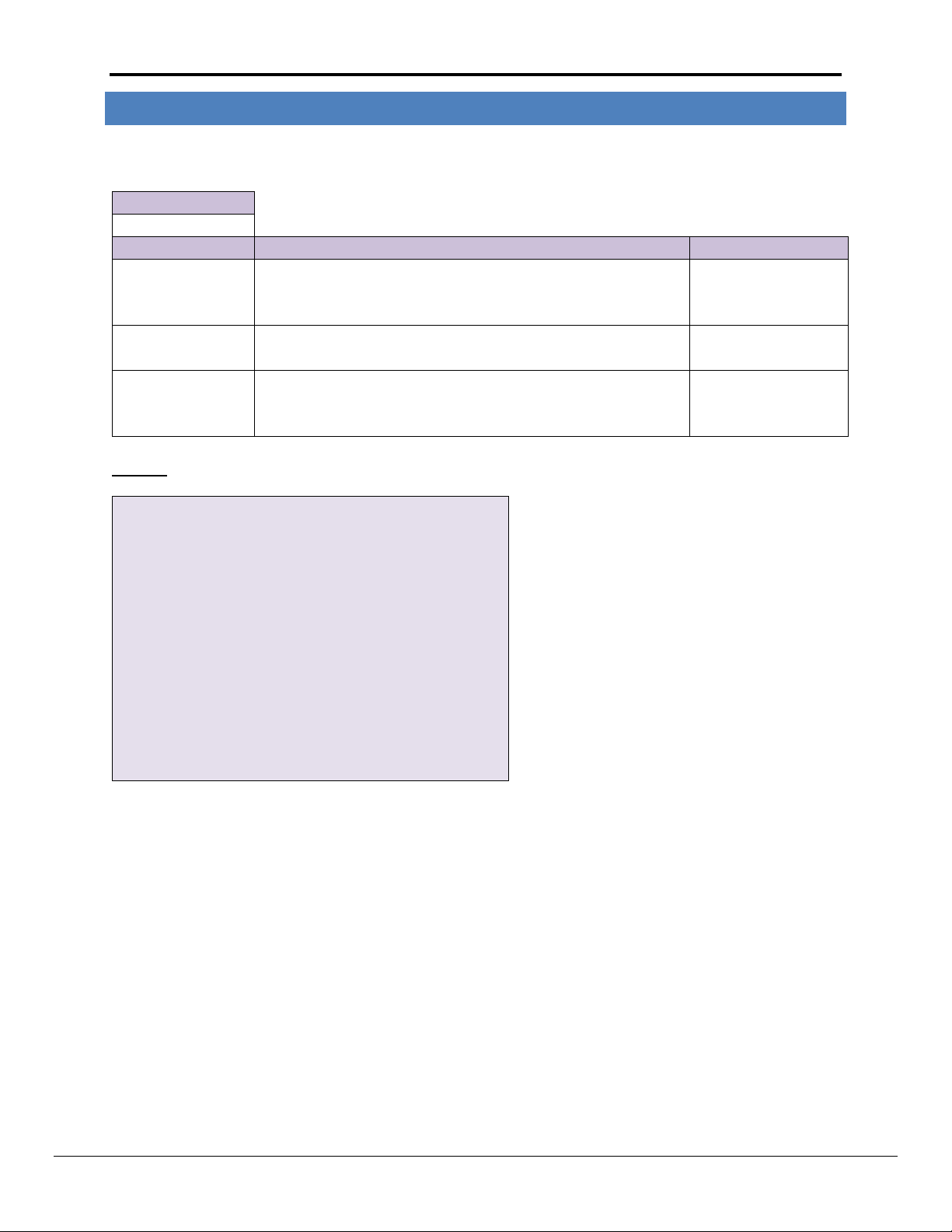
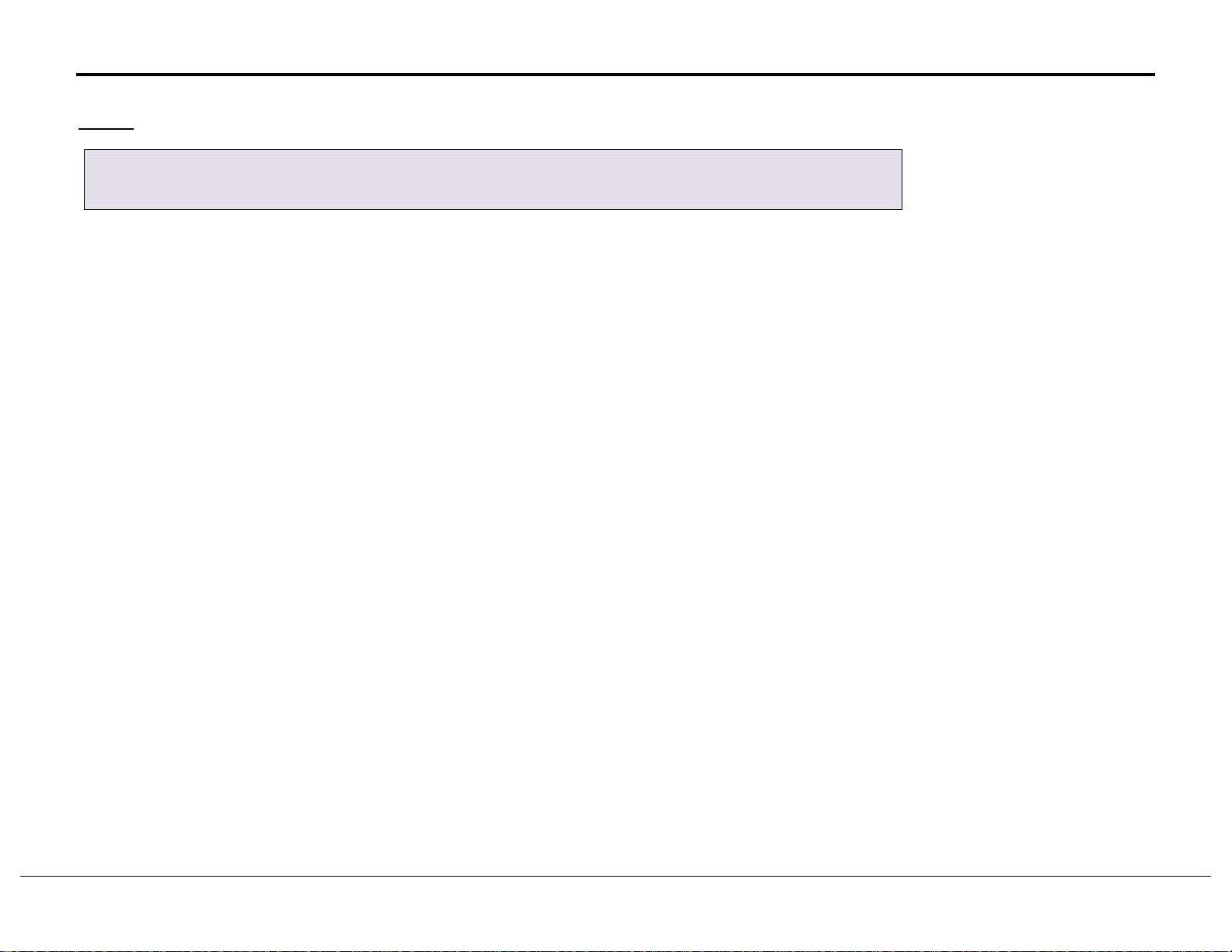
3 HARDWA R E CONNECTIONS
The FieldServer is connected to the Vesda as shown in connection drawing.
Configure the Vesda according to manufacturer’s instructions
FS-8917-03 Pinouts
FieldServer Technologies 1991 Tarob Court Milpitas, California 95035 USA Web: www.fieldserver.com
Tel: (408) 262 2299 Fax: (408) 262 2269 Toll Free: (888) 509 1970 email: support@fieldserver.com
Page 6
FS-8700-43 VESDA Driver Manual Page 6 of 28
Section Title
Data_Arrays
Column Title
Function
Legal Values
Data_Array_Name
Provide name for Data Array
Up to 15
alphanumeric
characters
Data_Array_Format
Provide data format. Each Data Array can only take on one
format.
Bit, Float, Byte
Data_Array_Length
Number of Data Objects. Must be larger than the data storage
area required by the Map Descriptors for the data being placed in
this array.
1-10, 000
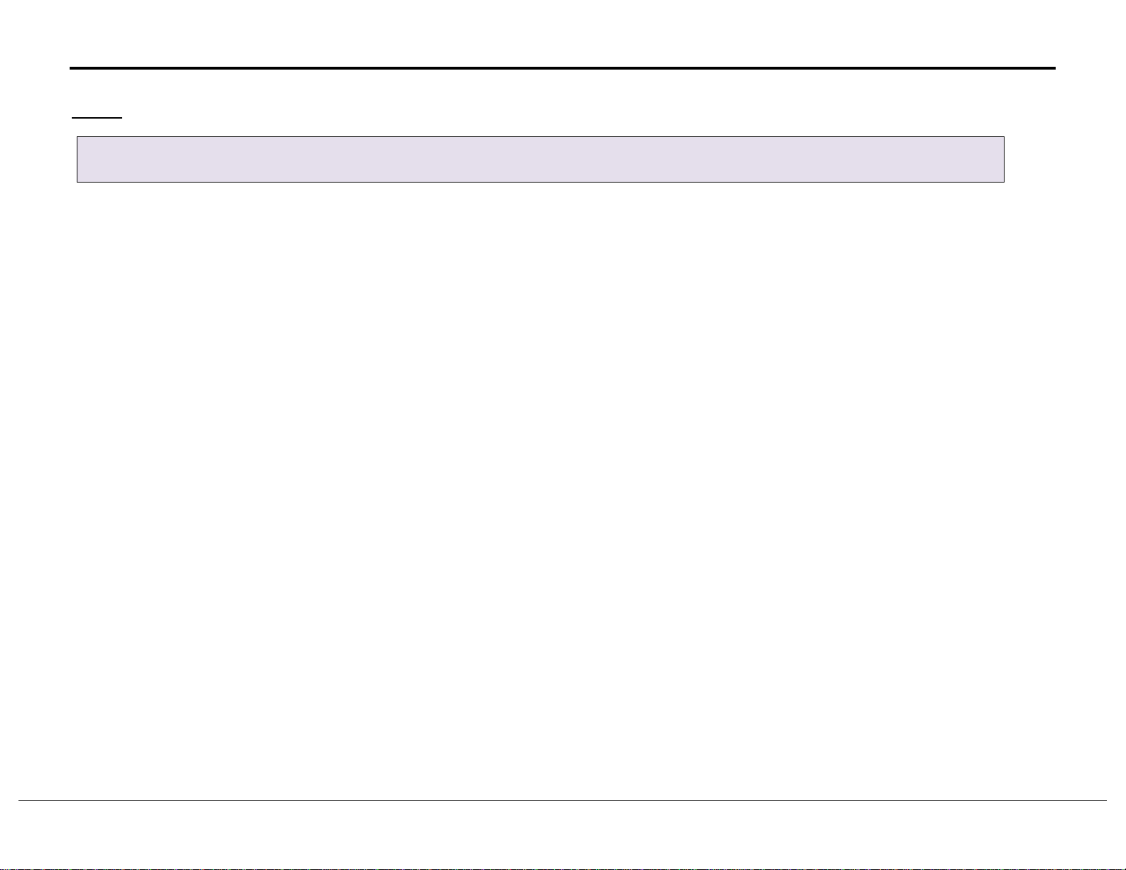
// Data Arrays
Data_Arrays
Data_Array_Name,
, Data_Format,
, Data_Array_Length
Set_Op,
, Bit,
, 32
VESDA01_1_f,
, Float,
, 32
VESDA01_1_b,
, Bit,
, 32
VESDA01_2_f,
, Float,
, 32
VESDA01_2_b,
, Bit,
, 32
VESDA01_3_f,
, Float,
, 32
VESDA01_3_b,
, Bit,
, 32
VESDA01_4_f,
, Float,
, 32
VESDA01_4_b,
, Bit,
, 32
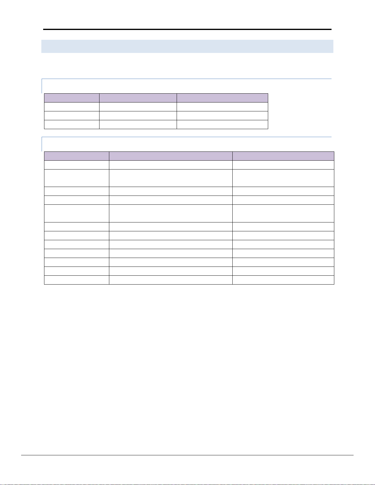
4 DATA A RRAY PARAMETER S
Data Arrays are “protocol neutral” data buffers for storage of data to be passed between protocols. It is necessary
to declare the data format of each of the Data Arrays to facilitate correct storage of the relevant data.
Example
FieldServer Technologies 1991 Tarob Court Milpitas, California 95035 USA Web: www.fieldserver.com
Tel: (408) 262 2299 Fax: (408) 262 2269 Toll Free: (888) 509 1970 email: support@fieldserver.com
Page 7
FS-8700-43 VESDA Driver Manual Page 7 of 28
Section Title
Connections
Column
Title
Function
Legal Values
Port
Specify which port the device is connected to the FieldServer
P1-P8, R1-R21
Baud*
Specify baud rate2
110 – 115200, standard
baud rates only. 9600
Parity*
Specify parity
None
Data_Bits*
Specify data bits
8
Stop_Bits*
Specify stop bits
1
Timeout*
Specify time allowed between poll and responses.
≤10s, 2s
IC_timeout*
This parameter monitors the time between characters in a response. If
the time exceeds the IC_Timeout the response is discarded and
considered a timeout.
0-1.0s, 0.5s
// Client Side Connections
//
Connections
Port
, Baud
, Data_bits
, Stop_bits
, Parity
, Timeout
, IC_Timeout
P1
, 9600
, 8
, 1
, None
, 10.0s
, 1.0s
1
2
5 CONFI G U RING THE F I ELDSERVER AS A VE S DA CLIEN T
For a detailed discussion on FieldServer configuration, please refer to the FieldServer Configuration Manual. The
information that follows describes how to expand upon the factory defaults provided in the configuration files
included with the FieldServer (See “.csv” sample files provided with the FieldServer).
This section documents and describes the parameters necessary for configuring the FieldServer to communicate
with a Vesda Server.
The configuration file tells the FieldServer about its interfaces, and the routing of data required. In order to enable
the FieldServer for Vesda communications, the driver independent FieldServer buffers need to be declared in the
“Data Arrays” section, the destination device addresses need to be declared in the “Client Side Nodes” section, and
the data required from the servers needs to be mapped in the “Client Side Map Descriptors” section. Details on
how to do this can be found below.
Note that in the tables, * indicates an optional parameter, with the bold legal value being the default.
5.1 Client Side Co n ne c t ion Para m eters
Example:
Not all ports shown are necessarily supported by the hardware. Consult the appropriate Instruction manual for details of the ports available
on specific hardware.
Most Vesda Panels are configured for Baud 19200.
FieldServer Technologies 1991 Tarob Court Milpitas, California 95035 USA Web: www.fieldserver.com
Tel: (408) 262 2299 Fax: (408) 262 2269 Toll Free: (888) 509 1970 email: support@fieldserver.com
Page 8

FS-8700-43 VESDA Driver Manual Page 8 of 28
Section Title
Nodes
Column Title
Function
Legal Values
Node_Name
Provide name for Node
Up to 32 alphanumeric characters
Protocol
Specify protocol used
VESDA
Port
Specify which port the device is connected to the FieldServer
P1-P8, R1-R23
Timeout*
Specify time allowed between poll and responses.
≤10s, 2s
// Client Side Nodes
Nodes
Node_Name
, Protocol
, Port
, Timeout
VESDA_HLI
, VESDA
, P1
, 10.0s
Column Title
Function
Legal Values
Map_Descriptor_Name
Name of this Map Descriptor
Up to 32 alphanumeric characters
Data_Array_Name
Name of Data Array where data is to be
stored in the FieldServer. Only used for
commands 1,4,6,12.
One of the Data Array names specified
in Section 4. Must be of type BIT
Data_Array_Location
Starting location in Data Array
0 to (Data_Array_Length -1) as
specified in Section 4.
Function
Function of Client Map Descriptor. A
Command is a write, and a Response is a
read
Rdbc, Wrbc, Wrbx, Awt
3
5.2 Client Side Node Parame t e rs
Example:
5.3 Client Side Map D escriptor Paramete r s
5.3.1 FieldServer Re l a t e d Map Desc r i p t o r Parameters
Not all ports shown are necessarily supported by the hardware. Consult the appropriate Instruction manual for details of the ports available
on specific hardware.
FieldServer Technologies 1991 Tarob Court Milpitas, California 95035 USA Web: www.fieldserver.com
Tel: (408) 262 2299 Fax: (408) 262 2269 Toll Free: (888) 509 1970 email: support@fieldserver.com
Page 9

FS-8700-43 VESDA Driver Manual Page 9 of 28
Column Title
Function
Legal Values
Node_Name
Name of Node to fetch data from
One of the Node names specified in
Section 5.1
Data_Type
Data type
Dig_input, Dig_output, -
Length
Length of Map Descriptor
1 to end of data block.
Address
Starting address of read block
The start bit number of the data of
interest
Command
The command id as given in the notes.
1, 4, 6, 10, 12, 16, 27, 29
Network*
The network number
0-255, 0
Zone*
The zone number
0-255, 0
Sector*
The sector number
1-255 or 0 to read the average smoke
level and highest alarms.
DA_Bit_Name*
Name of Data Array where data is to be
stored in the FieldServer. Used for
commands 10 and 16.
One of the Data Array names specified in
Section 4. Must be of type BIT, -
DA_Bit_Offset*
Starting location in Data Array. Used for
commands 10 and 16
0 to (Data_Array_Length -1) as specified
in Section 4, -
DA_Float_Name*
Name of Data Array where data is to be
stored in the FieldServer. Only used for
command 10.
One of the Data Array names specified in
Section 4. Must be of type FLOAT, -
DA_Float_Offset*
Starting location in Data Array. Only used
for command 10
0 to (Data_Array_Length -1) as specified
in Section 4, -
DA_Byte_Name*
Name of Data Array where data is to be
stored in the FieldServer. Only used for
command 16.
One of the Data Array names specified in
Section 4. Must be of type BYTE, -
DA_Byte_offset*
Starting location in Data Array. Only used
for command 16
0 to (Data_Array_Length -1) as specified
in Section 4, -
DA_Parameters
Name of Data Array where data is to be
stored in the FieldServer. Only used for
command 29.
One of the Data Array names specified in
Section 4. -
DA_Parameters_Offset
Starting location in Data Array. Only used
for command 29
0 to (Data_Array_Length -1) as specified
in Section 4, -
5.3.2 Driver Related M ap Descriptor P a r a meters
FieldServer Technologies 1991 Tarob Court Milpitas, California 95035 USA Web: www.fieldserver.com
Tel: (408) 262 2299 Fax: (408) 262 2269 Toll Free: (888) 509 1970 email: support@fieldserver.com
Page 10

FS-8700-43 VESDA Driver Manual Page 10 of 28
Map_Descriptors
Map_Descriptor_Name
, Data_Array_Name
, Data_Array_Offset
, Function
, Data_Type
, Node_Name
, Address
, Length
, Command
, Network
, Zone
, Sector
set_op_vesda_hli
, set_op
, 0
, Wrbc
, Dig_output
, VESDA_HLI
, 0
, 8
, 1
, 0
, 255
, -
Map_Descriptors
Map_Descriptor_Name
, Zone
, Sector
, Node_Name
, Function
, DA_Bit_Name
, DA_Float_Name
, DA_Bit_offset
, DA_Float_offset
, Data_Array_Offset
, Data_Type
, Command
, Network
, Address
, Length
rd_vesda_01_1
, 0
, 128
, VESDA_HLI
, rdbc
, VESDA01_1_
, VESDA01_1_f
, 0
, 0
, 0
, Dig_input
, 10
, 0
, 0
, 32
rd_vesda_01_2
, 0
, 64
, VESDA_HLI
, rdbc
, VESDA01_2_b
, VESDA01_2_f
, 0
, 0
, 0
, Dig_input
, 10
, 0
, 0
, 32
rd_vesda_01_3
, 0
, 32
, VESDA_HLI
, rdbc
, VESDA01_3_b
, VESDA01_3_f
, 0
, 0
, 0
, Dig_input
, 10
, 0
, 0
, 32
rd_vesda_01_4
, 0
, 16
, VESDA_HLI
, rdbc
, VESDA01_4_b
, VESDA01_4_f
, 0
, 0
, 0
, Dig_input
, 10
, 0
, 0
, 32
5.3.3 Map Descriptor Example
FieldServer Technologies 1991 Tarob Court Milpitas, California 95035 USA Web: www.fieldserver.com
Tel: (408) 262 2299 Fax: (408) 262 2269 Toll Free: (888) 509 1970 email: support@fieldserver.com
Page 11

FS-8700-43 VESDA Driver Manual Page 11 of 28
Column Title
Function
Legal Values
Data_Array_Name
Provide name for Data Array
Up to 15 alphanumeric characters
Data_Format
Provides data format
BIT
Data_Array_Length
Number of Data Objects
8
Column Title
Function
Legal Values
Map_Descriptor_Name
Name of this Map Descriptor
Up to 32 alphanumeric characters
Data_Array_Name
Name of Data Array where data is to be stored
in the FieldServer
Data_Array_Name defined in
Appendix A.1.1
Function
Function of Client Map Descriptor.
Wrbc, Wrbx
Node_Name
Name of Node to fetch data from
One of the Node names specified in
Section 5.2.
Data_Type
Data type
Dig_Output
Length
Length of Map Descriptor
1-16 (must not overflow the data
array)
Address*
Starting address of read block
0-15, 0
Command
The command ID
1
Network*
The network number
1-255, 0
Zone*
The zone number
1-255, 0
Sector*
The sector number
1-255, 0
Map_Descriptors
Map_Descriptor_Name
, Data_Array_Name
, Function
, Data_Type
, Node_Name
, Address
, Length
, Command
, Network
, Zone
, Sector
set_op_vesda_hli
, set_op
, Wrbc
, Dig_Output
, VESDA_HLI
, 0
, 8
, 1
, 0
, 0
, 0
Appendix A. Useful Features
Appendix A.1. VESDA mapping format for Command 1 (Set Operation)
This command is mandatory as it turns the VESDA system into a master slave relationship and is of type BIT. The
content of the data is irrelevant. The format for the data is as follows:
Appendix A.1.1. Data A r r a y s
Appendix A.1.2. Client S ide Map Descri p t ors
Appendix A.1.3. Exam p l e
FieldServer Technologies 1991 Tarob Court Milpitas, California 95035 USA Web: www.fieldserver.com
Tel: (408) 262 2299 Fax: (408) 262 2269 Toll Free: (888) 509 1970 email: support@fieldserver.com
Page 12
FS-8700-43 VESDA Driver Manual Page 12 of 28
Column Title
Function
Legal Values
Data_Array_Name
Provide name for Data Array
Up to 15 alphanumeric characters
Data_Format
Provides data format
BIT
Data_Array_Length
Number of Data Objects
1 - 16
Column Title
Function
Legal Values
Map_Descriptor_Name
Name of this Map Descriptor
Up to 32 alphanumeric characters
Data_Array_Name
Name of Data Array where data is to be
stored in the FieldServer
Data_Array_Name defined in Section
Appendix A.2.1
Data_Array_Location
Starting location in Data Array
0 -15
Function
Function of Client Map Descriptor.
Rdbc
Node_Name
Name of Node to fetch data from
One of the Node names specified in
Section 5.2.
Data_Type
Data type
Dig_input
Length
Length of Map Descriptor
1-16 (must not overflow the data array)
Address
Starting address of read block
0-15
Command
The command ID
4
Network*
The network number
1-255, 0
Zone*
The zone number
1-255, 0
Sector*
The sector number
1-255, 0
4
BIT offset
Function
BIT offset
Function
0
Other Zone Info
8
Fault Power
1
Scanning
9
Fault Urgent
2
Autolearning
10
Fault Zone
3
Normalising
11
Fault System
4
Isolated
12
Alarm Fire2
5
Fault Filter
13
Alarm Fire1
6
Fault Airflow
14
Alarm Action
7
Fault Network
15
Alarm Alert
4
Appendix A.2. VESDA mapping format for Command 4 (Zone Update)
This request returns the Current Zone Status in a BIT data array. The format for the data is as follows:
Appendix A.2.1. Data A r r a y s
Appendix A.2.2. Client S ide Map Descri p t ors
Appendix A.2.3. Data B l o ck Descriptio n
1 indicates TRUE; 0 indicates FALSE
FieldServer Technologies 1991 Tarob Court Milpitas, California 95035 USA Web: www.fieldserver.com
Tel: (408) 262 2299 Fax: (408) 262 2269 Toll Free: (888) 509 1970 email: support@fieldserver.com
Page 13
FS-8700-43 VESDA Driver Manual Page 13 of 28
Map_Descriptors
Map_Descriptor_Name
, Data_Array_Name
, Function
, Data_Type
, Node_Name
, Address
, Length
, Command
, Network
, Zone
, Sector
Get_zone_sb
, zone_inp
, Rdbc
, Dig_Input
, VESDA_HLI
, 0
, 16
, 4
, 0
, 0
, 0
Example
FieldServer Technologies 1991 Tarob Court Milpitas, California 95035 USA Web: www.fieldserver.com
Tel: (408) 262 2299 Fax: (408) 262 2269 Toll Free: (888) 509 1970 email: support@fieldserver.com
Page 14

FS-8700-43 VESDA Driver Manual Page 14 of 28
Column Title
Function
Legal Values
Data_Array_Name
Provide name for Data Array
Up to 32 alphanumeric characters
Data_Format
Provides data format
BIT
Data_Array_Length
Number of Data Objects
1 - 8
Column Title
Function
Legal Values
Map_Descriptor_Name
Name of this Map Descriptor
Up to 32 alphanumeric characters
Data_Array_Name
Name of Data Array where data is to be
stored in the FieldServer
Data_Array_Name defined in Section
Appendix A.3.1
Data_Array_Location
Starting location in Data Array
0 –7
Function
Function of Client Map Descriptor.
Wrbx
Node_Name
Name of Node to fetch data from
One of the Node names specified in
Section 5.2.
Data_Type
Data type
Dig_output
Length
Length of Map Descriptor
1-8 (must not overflow the data array)
Address
Starting address of read block
0-7
Command
The command ID
6
Network*
The network number
1-255, 0
Zone*
The zone number
1-255, 0
Sector*
The sector number
1-255, 0
56
BIT offset
Function
0
Stop Test
1
Scan Start
2
Start Test
3
Silence
4
De-Isolate
5
Isolate
6
Reset
7
Reserved
5
6
Appendix A.3. VESDA mapping format for Command 6 (Remote Input)
This command sends the Remote Input in a BIT data array.
Appendix A.3.1. Data A r r a y
Appendix A.3.2. Client M a p Descriptors
Appendix A.3.3. Data B l o ck Descriptio n
1 indicates TRUE; 0 indicates FALSE
ONLY 1 OF THE 8 BITS MAY BE SET IN ONE COMMAND
FieldServer Technologies 1991 Tarob Court Milpitas, California 95035 USA Web: www.fieldserver.com
Tel: (408) 262 2299 Fax: (408) 262 2269 Toll Free: (888) 509 1970 email: support@fieldserver.com
Page 15

FS-8700-43 VESDA Driver Manual Page 15 of 28
Map_Descriptors
Map_Descriptor_Name
, Data_Array_Name
, Function
, Data_Type
, Node_Name
, Address
, Length
, Command
, Network
, Zone
, Sector
Rem_inp_sb
, rem_inp
, Wrbc
, Dig_Output
, VESDA_HLI
, 0
, 8
, 6
, 0
, 0
, 0
Example
FieldServer Technologies 1991 Tarob Court Milpitas, California 95035 USA Web: www.fieldserver.com
Tel: (408) 262 2299 Fax: (408) 262 2269 Toll Free: (888) 509 1970 email: support@fieldserver.com
Page 16

FS-8700-43 VESDA Driver Manual Page 16 of 28
Column Title
Function
Legal Values
Data_Array_Name
Provide name for Data Array
Up to 15 alphanumeric characters
Data_Format
Provides data format
BIT
Data_Array_Length
Number of Data Objects
32
Column Title
Function
Legal Values
Data_Array_Name
Provide name for Data Array
Up to 15 alphanumeric characters
Data_Format
Provides data format
FLOAT
Data_Array_Length
Number of Data Objects
32 (only first position used)
Column Title
Function
Legal Values
Map_Descriptor_Name
Name of this Map Descriptor
Up to 32 alphanumeric characters
Data_Array_Location
Starting location in Data Array
0-31
Function
Function of Client Map Descriptor
Rdbc
Node_Name
Name of Node to fetch data from
One of the Node names specified in
Section 5.2.
Data_Type
Data type
Dig_input
Length
Length of Map Descriptor
32
Address
Starting address of read block
0-31
Command
The command id
10
Network*
The network number
1-255, 0
Zone*
The zone number
1-255, 0
Sector*
The sector number
1-255, 0
DA_Bit_Name
Name of Data Array where data is to be
stored in the FieldServer.
Data Array 1 name defined in Appendix
A.4.1
DA_Bit_Offset
Starting location in Data Array.
0 to (Data_Array_Length -1) as specified
in Appendix A.4.1
DA_Float_Name
Name of Data Array where data is to be
stored in the FieldServer.
Data Array 2 name defined in Appendix
A.4.2
DA_Float_Offset
Starting location in Data Array.
0 to (Data_Array_Length -1) as specified
in Appendix A.4.1
Appendix A.4. VESDA mapping format for command 10 (Update Display Status)
This request returns the Current Display Status in a split data array (2 data arrays of different type in one map
descriptor). The format for the data is as follows:
Appendix A.4.1. Data A r r a y s 1
Appendix A.4.2. Data A r r a y s 2
Appendix A.4.3. Client S ide Map Descri p t ors
FieldServer Technologies 1991 Tarob Court Milpitas, California 95035 USA Web: www.fieldserver.com
Tel: (408) 262 2299 Fax: (408) 262 2269 Toll Free: (888) 509 1970 email: support@fieldserver.com
Page 17

FS-8700-43 VESDA Driver Manual Page 17 of 28
7
BIT offset
Function
0
Reserved Flash
1
Fault Filter Flash
2
Fault Airflow Flash
3
Fault Network Flash
4
Fault Power Flash
5
Fault Urgent Flash
6
Fault Zone Flash
7
Fault System Flash
8
OK Flash
9
Isolate Flash
10
Fault Minor Flash
11
Fault Major Flash
12
Alarm Fire2 Flash
13
Alarm Fire1 Flash
14
Alarm Action Flash
15
Alarm Alert Flash
16
Reserved
17
Fault Filter
18
Fault Airflow
19
Fault Network
20
Fault Power
21
Fault Urgent
22
Fault Zone
23
Fault System
24
OK
25
Isolate
26
Fault Minor
27
Fault Major
28
Alarm Fire2
29
Alarm Fire1
30
Alarm Action
31
Alarm Alert
FLOAT offset
Function
0
Average Smoke Level (Sector must be set to zero)
7
Appendix A.4.4. Data B l o ck 1 Descri p t i o n
Appendix A.4.5. Data B l o ck 2 Descri p t i o n
1 indicates TRUE; 0 indicates FALSE
FieldServer Technologies 1991 Tarob Court Milpitas, California 95035 USA Web: www.fieldserver.com
Tel: (408) 262 2299 Fax: (408) 262 2269 Toll Free: (888) 509 1970 email: support@fieldserver.com
Page 18

FS-8700-43 VESDA Driver Manual Page 18 of 28
// Client Side Map Descriptors
Map_Descriptors
Map_Descriptor_Name
, Zone
, Sector
, Network
, Command
, Node_Name
, Function
, DA_Bit_Name
, DA_Float_Name
, DA_Bit_offset
, DA_Float_offset
, Data_Array_Location
, Data_type
, Address
, Length
rd_vesda_01_1
, 0
, 128
, 0
, 10
, VESDA_HLI
, Rdbc
, VESDA01_1_b
, VESDA01_1_f
, 0
, 0
, 0
, Dig_Input
, 0
, 32
rd_vesda_01_2
, 0
, 64
, 0
, 10
, VESDA_HLI
, Rdbc
, VESDA01_2_b
, VESDA01_2_f
, 0
, 0
, 0
, Dig_Input
, 0
, 32
rd_vesda_01_3
, 0
, 32
, 0
, 10
, VESDA_HLI
, Rdbc
, VESDA01_3_b
, VESDA01_3_f
, 0
, 0
, 0
, Dig_Input
, 0
, 32
rd_vesda_01_4
, 0
, 16
, 0
, 10
, VESDA_HLI
, Rdbc
, VESDA01_4_b
, VESDA01_4_f
, 0
, 0
, 0
, Dig_Input
, 0
, 32
rd_vesda_01_1
, 1
, -
, -
, 10
, VESDA_HLI
, Rdbc
, VESDA01_1_b
, VESDA01_1_f
, 0
, 0
, 0
, Dig_Input
, 0
, 32
Update Display Status:
Note that the Sector is
specified as a bitmask.
For Sector 1 – Specify 128
For Sector 2 – Specify 64
For Sector 3 – Specify 32
For Sector 4 – Specify 16
Overall Smoke Level
and Highest Alarms.
(Sector must be zero)
Example
FieldServer Technologies 1991 Tarob Court Milpitas, California 95035 USA Web: www.fieldserver.com
Tel: (408) 262 2299 Fax: (408) 262 2269 Toll Free: (888) 509 1970 email: support@fieldserver.com
Page 19

FS-8700-43 VESDA Driver Manual Page 19 of 28
Column Title
Function
Legal Values
Data_Array_Name
Provide name for Data Array
Up to 15 alphanumeric characters
Data_Format
Provides data format
BYTE
Data_Array_Length
Number of Data Objects
1 – 21
Column Title
Function
Legal Values
Map_Descriptor_Name
Name of this Map Descriptor
Up to 32 alphanumeric characters
Data_Array_Name
Name of Data Array where data is to be stored
in the FieldServer
Data_Array_Name defined in
Appendix A.5.1
Data_Array_Location
Starting location in Data Array
0-20
Function
Function of Client Map Descriptor.
Rdbc
Node_Name
Name of Node to fetch data from
One of the Node names specified in
Section 5.2.
Data_Type
Data type
Dig_input
Length
Length of Map Descriptor
1-21 (must not overflow the data
array)
Address
Starting address of read block
0-20
Command
The command id
12
Network*
The network number
1-255, 0
Zone*
The zone number
1-255, 0
Sector*
The sector number
1-255, 0
8
BYTE offset
Function
0
Number of faults
1 - 20
Fault list
8
Appendix A.5. VESDA mapping format for command 12 (Current Fault Status)
This command sends the Current Fault Status in a BYTE data array. The format for the data is as follows:
Appendix A.5.1. Data A rrays
Appendix A.5.2. Client S ide Map D e s c riptors
Appendix A.5.3. Data B l o ck Descriptio n
1 indicates TRUE; 0 indicates FALSE
FieldServer Technologies 1991 Tarob Court Milpitas, California 95035 USA Web: www.fieldserver.com
Tel: (408) 262 2299 Fax: (408) 262 2269 Toll Free: (888) 509 1970 email: support@fieldserver.com
Page 20

FS-8700-43 VESDA Driver Manual Page 20 of 28
Map_Descriptors
Map_Descriptor_Name
, Data_Array_Name
, Function
, Data_Type
, Node_Name
, Address
, Length
, Command
, Network
, Zone
, Sector
Cfs_inp_sb
, cfs_inp
, Rdbc
, Dig_Input
, VESDA_HLI
, 0
, 21
, 12
, 0
, 0
, 0
Example
FieldServer Technologies 1991 Tarob Court Milpitas, California 95035 USA Web: www.fieldserver.com
Tel: (408) 262 2299 Fax: (408) 262 2269 Toll Free: (888) 509 1970 email: support@fieldserver.com
Page 21

FS-8700-43 VESDA Driver Manual Page 21 of 28
Column Title
Function
Legal Values
Data_Array_Name
Provide name for Data Array
Up to 15 alphanumeric characters
Data_Format
Provides data format
BIT
Data_Array_Length
Number of Data Objects
4
Column Title
Function
Legal Values
Data_Array_Name
Provide name for Data Array
Up to 15 alphanumeric characters
Data_Format
Provides data format
BYTE
Data_Array_Length
Number of Data Objects
4
Column Title
Function
Legal Values
Map_Descriptor_Name
Name of this Map Descriptor
Up to 32 alphanumeric characters
Data_Array_Location
Starting location in Data Array
0
Function
Function of Client Map Descriptor
Rdbc
Node_Name
Name of Node to fetch data from
One of the Node names specified in
Section 5.2.
Data_Type
Data type
Dig_input
Length
Length of Map Descriptor
4
Address
Starting address of read block
0-3
Command
The command id
16
Network*
The network number
1-255, 0
Zone*
The zone number
1-255, 0
Sector*
The sector number
1-255, 0
DA_Bit_Name
Name of Data Array where data is to be
stored in the FieldServer.
Data Array 1 name defined in Appendix
A.6.1
DA_Bit_offset
Starting location in Data Array.
0 to (Data_Array_Length -1) as specified
in Appendix A.6.1
DA_Byte_Name
Name of Data Array where data is to be
stored in the FieldServer.
Data Array 2 name defined in Appendix
A.6.2
DA_Byte_offset
Starting location in Data Array.
0 to (Data_Array_Length -1) as specified
in Appendix A.6.1
Appendix A.6. VESDA mapping format for command 16 (Update Airflow Status)
This request returns the Current Airflow Status in a split data array (2 data arrays of different type in one map
descriptor). The format for the data is as follows:
Appendix A.6.1. Data Arrays 1
Appendix A.6.2. Data A rrays 2
Appendix A.6.3. Client S ide Map Descri p t ors
FieldServer Technologies 1991 Tarob Court Milpitas, California 95035 USA Web: www.fieldserver.com
Tel: (408) 262 2299 Fax: (408) 262 2269 Toll Free: (888) 509 1970 email: support@fieldserver.com
Page 22

FS-8700-43 VESDA Driver Manual Page 22 of 28
9
BIT offset
Function
0
Pipe1 status
1
Pipe2 status
2
Pipe3 status
3
Pipe4 status
BYTE offset
Function
0
Airflow in pipe 1 as percentage of normalised pipe airflow.
1
Airflow in pipe 2 as percentage of normalised pipe airflow.
2
Airflow in pipe 3 as percentage of normalised pipe airflow.
3
Airflow in pipe 4 as percentage of normalised pipe airflow.
9
Appendix A.6.4. Data B l o ck 1 Descri p t i o n
Appendix A.6.5. Data B l o ck 2 Descri p t i o n
1 indicates OPEN; 0 indicates CLOSE
FieldServer Technologies 1991 Tarob Court Milpitas, California 95035 USA Web: www.fieldserver.com
Tel: (408) 262 2299 Fax: (408) 262 2269 Toll Free: (888) 509 1970 email: support@fieldserver.com
Page 23

FS-8700-43 VESDA Driver Manual Page 23 of 28
Map_Descriptors
Map_Descriptor_Name
, Data_Bit_Name
, DA_Byte_Name
, DA_Bit_Offset
, DA_Byte_Offset
, Data_Array_Location
, Function
, Data_Type
, Node_Name
, Address
, Length
, Command
, Network
, Zone
, Sector
Get_uas_sb
, uas_inp_bi
, uas_inp_by
, 0
, 0
, 0
, Rdbc
, Dig_Input
, VESDA_HLI
, 0
, 4
, 16
, 0
, 0
, 0
Example
FieldServer Technologies 1991 Tarob Court Milpitas, California 95035 USA Web: www.fieldserver.com
Tel: (408) 262 2299 Fax: (408) 262 2269 Toll Free: (888) 509 1970 email: support@fieldserver.com
Page 24
FS-8700-43 VESDA Driver Manual Page 24 of 28
Column Title
Function
Legal Values
Data_Array_Name
Provide name for Data Array
Up to 15 alphanumeric characters
Data_Format
Provides data format
Float
Data_Array_Length
Number of Data Objects
12
Column Title
Function
Legal Values
Map_Descriptor_Name
Name of this Map Descriptor
Up to 32 alphanumeric characters
Data_Array_Name
Name of Data Array where data is to be stored
in the FieldServer
Data_Array_Name defined in
Appendix A.7.1
Data_Array_Location
Starting location in Data Array
0
Function
Function of Client Map Descriptor.
Rdbc
Node_Name
Name of Node to fetch data from
One of the Node names specified in
Section 5.2.
Data_Type
Data type
-
Length
Length of Map Descriptor
12
Address
Starting address of read block
0
Command
The command ID
27
Network*
The network number
1-255, 0
Zone*
The zone number
1-255, 0
Sector*
The sector number
1-255, 0
Appendix A.7. VESDA mapping format for command 27 (Get Overall Smoke Thresholds)
This request returns the Overall Smoke Thresholds in a FLOAT data array. The format for the data is as follows:
Appendix A.7.1. Data A r r a y s
Appendix A.7.2. Client S ide Map D e s c riptors
FieldServer Technologies 1991 Tarob Court Milpitas, California 95035 USA Web: www.fieldserver.com
Tel: (408) 262 2299 Fax: (408) 262 2269 Toll Free: (888) 509 1970 email: support@fieldserver.com
Page 25

FS-8700-43 VESDA Driver Manual Page 25 of 28
Map_Descriptors
Map_Descriptor_Name
, Data_Array_Name
, Data_Array_Location
, Function
, Data_Type
, Node_Name
, Address
, Length
, Command
, Network
, Zone
, Sector
Read_Smoke_Thresh
, Rd_Smoke_Ths
, 0
, Rdbc
, -
, VESDA_HLI
, 0
, 12
, 27
, 0
, 5
, 0
Example
FieldServer Technologies 1991 Tarob Court Milpitas, California 95035 USA Web: www.fieldserver.com
Tel: (408) 262 2299 Fax: (408) 262 2269 Toll Free: (888) 509 1970 email: support@fieldserver.com
Page 26

FS-8700-43 VESDA Driver Manual Page 26 of 28
Column Title
Function
Legal Values
Data_Array_Name
Provide name for Data Array
Up to 15 alphanumeric characters
Data_Format
Provides data format
Bit
Data_Array_Length
Number of Data Objects
1
Column Title
Function
Legal Values
Map_Descriptor_Name
Name of this Map Descriptor
Up to 32 alphanumeric characters
Data_Array_Name
Name of Data Array where data is to be
stored in the FieldServer
Data_Array_Name defined in
Appendix A.8.1
Data_Array_Location
Starting location in Data Array
0
Function
Function of Client Map Descriptor.
AWT
Node_Name
Name of Node to fetch data from
One of the Node names specified in
Section 5.2.
Data_Type
Data type
-
Length
Length of Map Descriptor
1
Address
Starting address of read block
0
Command
The command ID
29
Network*
The network number
1-255, 0
Zone*
The zone number
1-255, 0
Sector*
The sector number
1-255, 0
DA_Parameters*
Name of Data Array where data is to be
stored in the FieldServer.
Data Array Name defined in
Appendix A.8.1
DA_Parameters_Offset*
Starting location in Data Array.
0
10
10
Bit offset
Function
0
Alert Smoke Threshold Day
1
Action Smoke Threshold Day
2
Fire-1 Smoke Threshold Day
3
Fire-2 Smoke Threshold Day
4
Alert Smoke Threshold Night
5
Action Smoke Threshold Night
6
Fire-1 Smoke Threshold Night
7
Fire-2 Smoke Threshold Night
Bit offset
Function
8
Sector Scanner for LaserScanner
Sector 1
9
Sector Scanner for LaserScanner
Sector 2
10
Sector Scanner for LaserScanner
Sector 3
11
Sector Scanner for LaserScanner
Sector 4
Appendix A.8. VESDA mapping format for command 29 (Set Smoke Thresholds)
This command sets the Smoke Thresholds. The format for the data is as follows:
Appendix A.8.1. Data A r r a y s
Appendix A.8.2. Client S ide Map D e s c riptors
Appendix A.8.3. Data B l o ck Descriptio n
1 indicates TRUE; 0 indicates FALSE
FieldServer Technologies 1991 Tarob Court Milpitas, California 95035 USA Web: www.fieldserver.com
Tel: (408) 262 2299 Fax: (408) 262 2269 Toll Free: (888) 509 1970 email: support@fieldserver.com
Page 27
FS-8700-43 VESDA Driver Manual Page 27 of 28
Map_Descriptors
Map_Descriptor_Name
, Data_Array_Name
, Data_Array_Location
, Function
, Data_Type
, Node_Name
, Address
, Length
, Command
, Network
, Zone
, Sector
, DA_Parameters
, DA_Parameters_Offset
Write_Smoke_Thresh
, Write_Triggers
, 0
, Awt
, -
, VESDA_HLI
, 0
, 1
, 29
, 0
, 5
, 0
, Write_Value
, 0
Example
FieldServer Technologies 1991 Tarob Court Milpitas, California 95035 USA Web: www.fieldserver.com
Tel: (408) 262 2299 Fax: (408) 262 2269 Toll Free: (888) 509 1970 email: support@fieldserver.com
Page 28

FS-8700-43 VESDA Driver Manual Page 28 of 28
Appendix B. Troubleshooting
Appendix B.1. VESDA Panel start-up delay.
When the HLI is powered on the FieldServer will not be able to communicate with the Panel for 10 to 30 seconds.
During this time the HLI starts up its application code and initializes various internal parameters.
Appendix B.2. Reading Smoke Levels on the VESDA Panels
The Vesda panel only allows the driver to read the average Smoke Level on all the ports. Polling for individual
sector smoke levels will always return a value of zero.
Zone setup - If the zone on the Panel has not been configured the zone must be set to zero in the
FieldServer configuration file.
Sector setup - Setting the sector to zero will allow the driver to poll for the average smoke level.
Refer to Appendix A.4 for more information.
FieldServer Technologies 1991 Tarob Court Milpitas, California 95035 USA Web: www.fieldserver.com
Tel: (408) 262 2299 Fax: (408) 262 2269 Toll Free: (888) 509 1970 email: support@fieldserver.com
 Loading...