

Field Scout TDR 350 Product Manual

TDR 350
Soil Moisture Meter
PRODUCT MANUAL
Item # 6435
Distributed & Supported By:
www.edaphic.com.au
info@edaphic.com.au
Ph: 1300 430 928

2
CONTENTS
Shaft Dimensions 4
Specifications 5
Batteries 6
Button Functions 8
Display Screens 10
Meter Calibration 14
Updating Firmware 15
Electrical Conductivity 16
Meter Operation 18
Replacing or Re-attaching the Probe Block 21
Field Scout Mobile App/SpecConnect 22
Data Logs 24
VWC Measurements 26
GPS 27
Appendix 1: Soil-Specific Calibration 28
Appendix 2: Checking VWC Readings 30
Appendix 3: FAQ 31
Appendix 4: Time Zone Corrections 32
This manual will familiarize you with the features and operation of
your new Field ScoutTM TDR 350 Soil Moisture Meter. Please read
this manual thoroughly before using your instrument.

3
Thank you for purchasing the Field ScoutTM TDR 350
soil moisture, electrical conductivity and soil surface
temperature meter. This manual describes the meter's
general features and operation.
Soil moisture is a critical, and potentially highly variable, component of the soil environment. Time domain
reflectometry is a proven technology for quickly and
accurately determining volumetric water content
(VWC) in soil. Electrical conductivity (EC) is a function of the moisture and salt in the soil. The meter also
measures soil surface temperature. The user can quickly
transition between taking VWC readings in standard
and high-clay mode.
The TDR 350's shaft-mounted probe allows the user to
take measurements while standing. The meter’s built-in
data logger can record data from several sites and eliminates the need to record data manually. The data points
can be viewed with the FieldScout Mobile app that
maps out soil measurements on logged GPS locations or
measurements can be saved to a USB drive that is
plugged into the built-in USB port.
Contents
Your shipment includes the following components:
- TDR 350 meter (in collapsed position)
- Carrying case
- 4 AA batteries
Note: TDR rods are sold separately
General overview
4
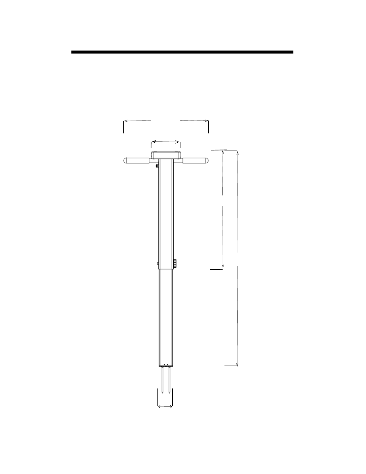
Shaft dimensions
The following are the dimensions of a fully extended
shaft. It is possible to reduce the length of the meter to
23” (58.5 cm) by adjusting the lower half of the shaft.
38"
19.5"
2.4"
14"
5"

5
Measurement
Units
Percent volumetric water content (VWC)
Period (raw sensor reading)
Resolution
VWC: 0.1% VWC units
EC: 0.01 mS/cm
Temperature: 0.2 ˚F (0.1 ˚C)
Accuracy
VWC: ±3.0% volumetric water content
with electrical conductivity < 2 mS/cm
EC: ± 0.1 mS/cm
Temperature: ± 1.8 ˚F (± 1 ˚C)
Range
VWC: 0% to saturation (Saturation is typi-
cally around 50% volumetric water)
EC: 0 to 5 mS/cm
Temperature: -22 to 140 ˚F (-30 to 60 ˚C)
Power
4 AA batteries
Lithium batteries will optimize battery life
Logger
Capacity
50,000 measurements
Display
Backlit, high-contrast, graphic LCD
GPS
Accuracy < 2.5m
Weight
4.3 lbs. (1.9 kg)
Probe Head
Dimensions
2.4” x 1.4”
(6cm x 3.5cm)
Shaft
Dimensions
Extended Length: 38” (96.5cm)
Collapsed Length: 23” (58.4cm)
Width: 1.4” (3.5cm)
Available
Rod
Dimensions
Turf 1.5” (3.8cm),
Short 3” (7.6cm),
Medium 4.7” (12cm)
Long 7.9” (20cm)
Diameter: 0.2” (0.5cm)
Spacing: 1.2” (3cm)
Specifications
6
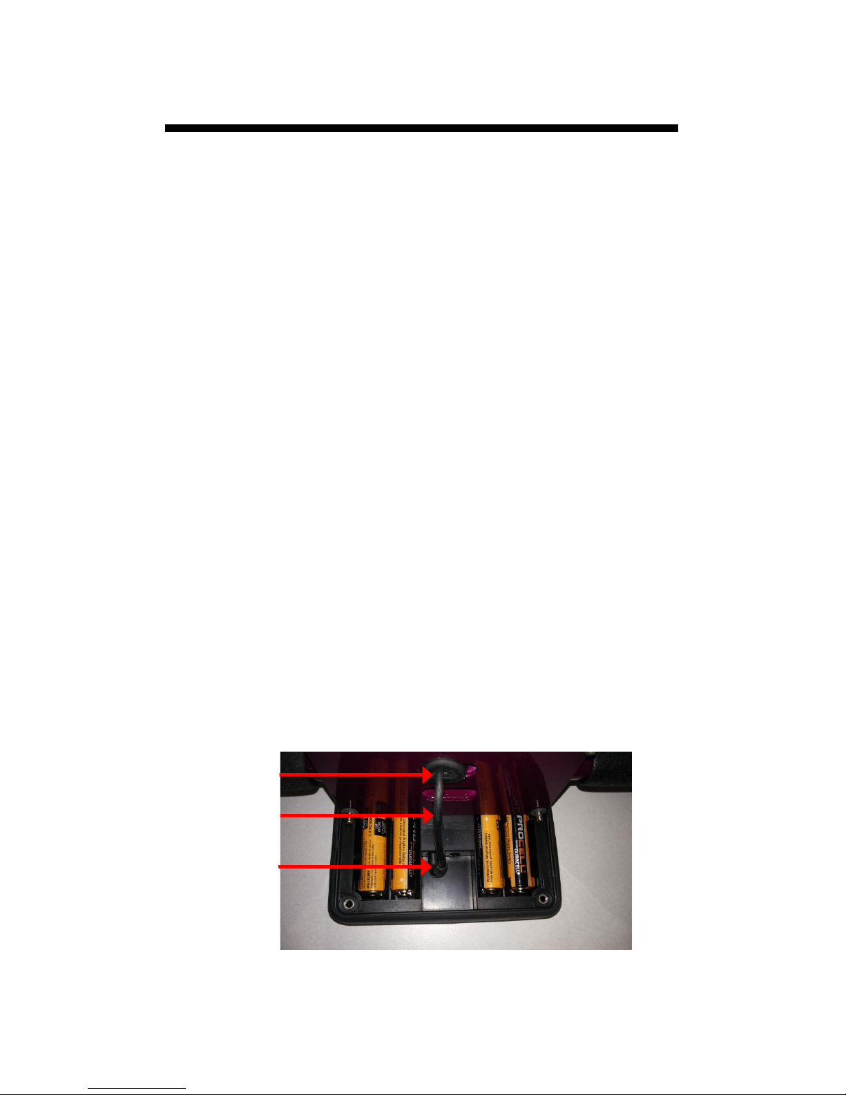
Changing the batteries
The TDR 350 requires 4 AA batteries. The battery holder
is on the underside of the display unit. The sensor is attached to the display via a cable that is plugged into a
socket between the battery holders. The cable can be
pulled out of and pushed back into the shaft through a
grommet at the top of the shaft.
STEPS:
1. Turn the TDR 350 upside down and remove the 4
screws. Open the bottom and separate the display
module from the base plate. This may require pulling
the cable slightly out of the shaft.
2. Unplug the cable connector from the jack to completely detach the display from the base.
3. Install batteries and ensure correct polarity by referencing the (+) positive and (-) negative labels at either
end of each slot.
4. Plug the cable connector back into the larger stereo
jack.
5. Mount the display box back onto the base plate. As
you do this, feed the cable back into the grommet.
6. Reattach the 4 screws.
Batteries
cable
plug
grommet
7
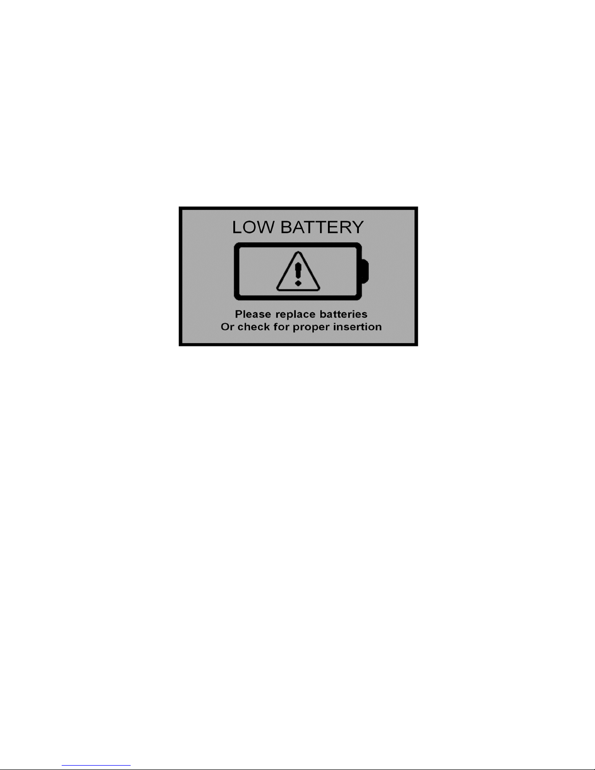
Battery life
The battery level is checked every time the display
unit is turned on. If the battery level is low, or if a
battery is inserted incorrectly, this low battery image shows on the full screen for about 10 seconds
and then the display will automatically turn off.
In addition to frequency of use, battery life is im-
pacted by use of the backlight and GPS receiver. If
not needed, the GPS feature should be disabled.
The backlight can be set to AUTO mode (p. 12).
This allows enough time to see the reading without
unduly taxing the battery.
8
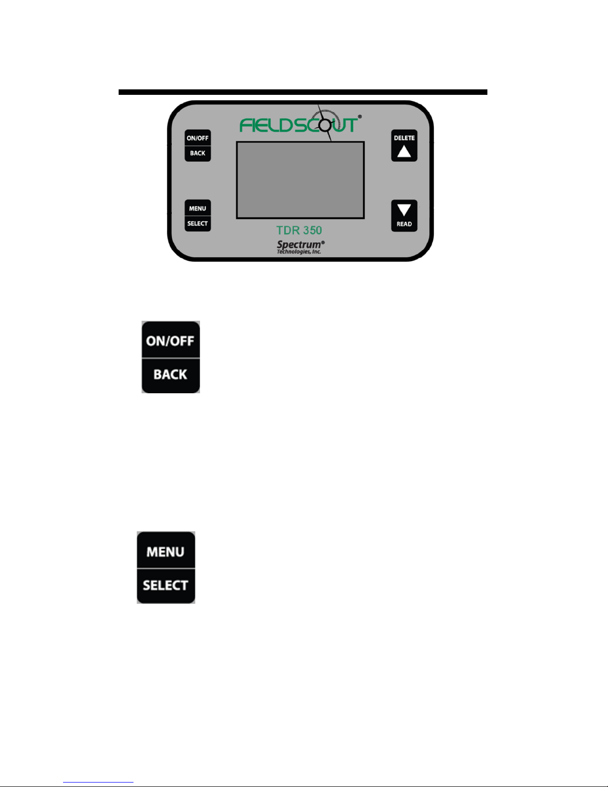
Button Functions
Basic Button Operations
ON/OFF or BACK button
Press this button briefly to turn on the
display. The meter will then display
the Data screen (p. 11). To turn the
meter off, press and hold this button
for about 2 seconds.
When in the Settings Menu screen (p. 12), press
this button to return to the Data screen. If you are
in a settings option that requires its own screen,
this button will return you to the Settings Menu
screen
MENU or SELECT button
When in the Data screen, press this but-
ton to go to the settings menu screen (p.
12). When in the Settings Menu screen
and on a menu option, press this button
to browse through the different choices
for that specific menu selection. In
some cases, selecting a settings option will take
you to another screen for further action.
9
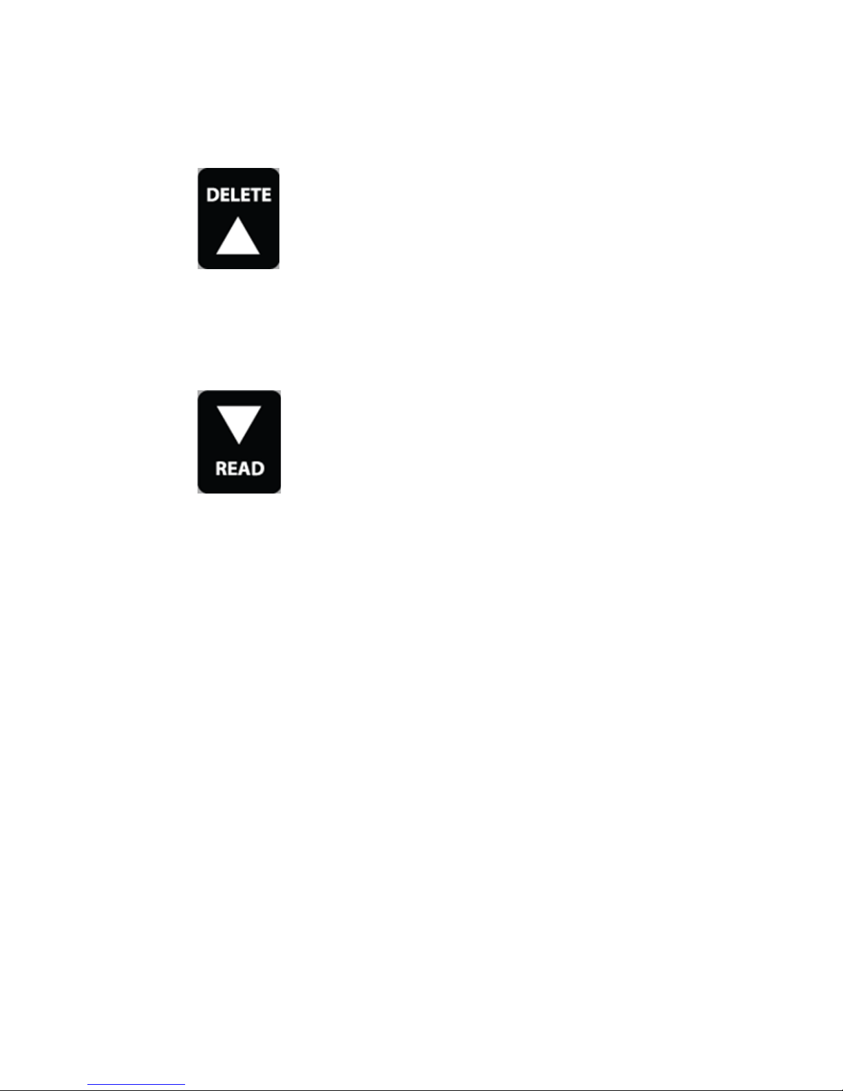
DELETE or UP button
When on the Data screen (p. 11), press
this button to delete the last measured
data point from the computed Average
and decrement the Count.
When on the Settings Menu screen (p. 12), press
this button to scroll up to the previous menu item.
READ or DOWN button
When on the Data screen, press and
release this button to take a sensor
reading. Press and hold to clear the average and reset the sample count to 0.
When on the Settings Menu screen, press this but-
ton to scroll down to the next menu item.
10
Display Screens
The TDR 350 has 3 main display screens;
- Startup Information screen
- Data screen
- Settings Menu screen
Startup Information screen
The Startup Information screen is displayed for
about 2 seconds after the display is turned on.
If desired, the startup screen can be kept on for a
longer duration. While powering up the meter,
press and hold the On/Off/Back button to continue displaying the Startup Device Information
screen. Release the button to proceed to the Data
screen.
11
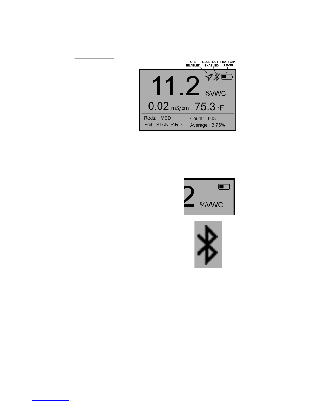
Data screen
Readings from
the sensor are
displayed on the
Data screen. The
battery level indicator appears
in the upper right
corner. The running average and
number of readings included in that average are
shown in the lower right corner. Pressing and
holding the READ button will clear the average
and re-set the counter to 0.
When disabled, the GPS and/or
Bluetooth icons will no longer
be visible. When visible, the
GPS icon will indicate the quality of the GPS fix (p. 27).
When the Bluetooth is enabled
but the TDR is not connected to
a mobile device, the Bluetooth
icon has a bar through I (see image in data screen at top of
page). When the TDR is connected to a mobile device, the bar is removed (see
image to the right).
 Loading...