

Page 1
Fieldpiece
4 Port Wireless
Manifold & Micron
Gauge
OPERATOR'S MANUAL
Model SMAN460
01
Quick Start
1 Install six AA batteries into rear battery com-
partment. Batteries included in packaging.
2 Press the center blue button for 1 second to
turn on your new manifold.
3 Connect hoses and pipe clamps to the mani-
fold and the system.
4 See real-time pressure and temperature mea-
surements all at once!
Certifications
FCC ID: VEARF915A
C-Tick (N22675)
CE
RoHS Compliant
02
Description
Your SMAN460 is the top of the line Wireless
4 Port Manifold and Micron Gauge for HVACR
professionals. See all your pressures and
temperatures at the same time on the redesigned
large display with bright blue backlight.
SMAN460 combines high precision, absolute
pressure sensors, a superheat/subcooling
calculator, true micron gauge for vacuum,
and dual temperature measurements. Your
SMAN460 calculates and displays target
superheat and actual superheat to verify proper
charge. SMAN460’s large 3/8” VAC port and true
3/8” bore throughout the block allow for quicker
recovery and evacuations.
Your SMAN460 is designed to meet the
demands of HVACR eld service with a rugged
rubber boot for durability, a strong metal
hanger for easy storage and a form tting, water
resistant, padded nylon pouch.
Use additional wireless products like
SDP2 Dual In-Duct Psychrometer to receive
temperature measurements wirelessly for realtime target superheat calculations.
03
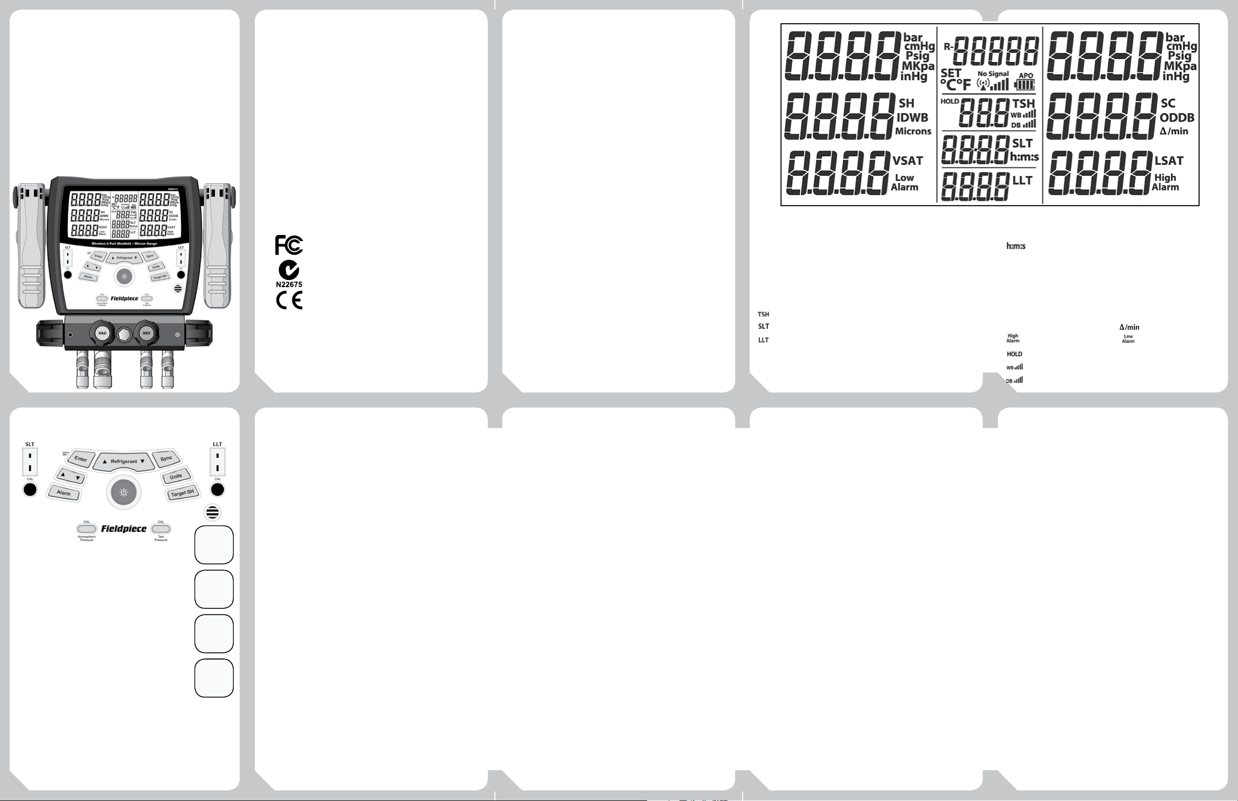
Pressure (bar)
Pressure (pounds/in2)
Pressure (kilopascals or Megapascals)
Negative Pressure (inches of mercury)
Negative Pressure (cm of mercury)
Superheat
Subcooling
Target Superheat
Suction Line Temperature
Liquid Line Temperature
Vapor Saturation Temperature
Liquid Saturation Temperature
04
Outdoor Dry Bulb
Indoor Wet Bulb
Hours:Minutes or Minutes:Seconds
Battery Life Connection Strength
Auto Power O Enabled
Wireless Signal Lost
Selected Refrigerant of System
Vacuum (Microns of Mercury)
Set Mode Rate of change
High Alarm Low Alarm
Static Target Superheat Calculation
IDWB Connection Strength
ODDB Connection Strength
05
Controls
5
6
8
10
3 4
11
1 Insert Type K thermocouple plugs here.
2 Temperature calibration pots.
3 Press to zero atmospheric pressure.
4 Press to calibrate to refrigerant tank.
(See Advanced Pressure Calibration section.)
5 Press to conrm selection.
6 Press/hold to cycle through refrigerants.
7 Hold 1 second to enable wireless functionality.
8 Press up or down arrow to adjust values.
9 Press to change units.
10 Press to turn on/o the Hi/Lo vacuum
alarms and hold to change alarm settings.
11 Hold 1 second to power on or o. Press to toggle backlight.
12 Press to enter Target Superheat setup mode.
13 Turn clockwise to close High side port.
14 Turn clockwise to close Low side port.
15 Turn clockwise to close 3/8" Vacuum port.
16 Turn clockwise to close Refrigerant port.
06
7
9
12
13
14
15
16
Functions
11
22
Superheat and Subcooling
Your SMAN460 can calculate and display both superheat and
subcooling simultaneously.
1 Select the appropriate refrigerant using the REFRIGERANT button.
2 Connect EPA approved refrigerant hoses to low and high side on
SMAN460. Plug Type K thermocouple pipe clamps to SLT and LLT.
3 Connect your SMAN460 to the system:
Superheat: Hand tighten low side hose to suction line service
port. Place the SLT pipe clamp thermocouple on the suction line
between the evaporator and compressor, no closer than 6 inches
to compressor.
Subcooling: Hand tighten high side hose to liquid line service
port. Attach the LLT pipe clamp thermocouple on the liquid line
between the condenser and expansion valve (TXV), as close to the
service port as possible.
4 After turning the system on or making any adjustments to
the system wait 15 minutes before charging by superheat or
subcooling to ensure the system is stabilized.
5 To add or remove refrigerant connect a refrigerant or recovery
cylinder to the REF port on SMAN460. Follow recommneded
charging or recovery practices from equipment manufacturer. Use
the low side, high side, and REF valves on SMAN460 to charge or
recover refrigerant as needed. Let system stabilize for 15 minutes.
Note: When superheat and/or subcooling cannot be calculated an
"OL" or "-OL" will be displayed. Please check the following:
1 The correct refrigerant is selected on the SMAN.
2 The pipe thermocouples are plugged into SLT/LLT ports and are in
good working condition.
3 The pipe thermocouples are attached in the appropriate location on
the system. See step 3 above for details.
07
Target Superheat
Target Superheat is useful for charging xed orice air conditioning
systems. Your SMAN460 can receive real-time indoor wet bulb (IDWB)
and outdoor dry bulb (ODDB) temperatures wirelessly to calculate realtime target superheat. The IDWB and ODDB values can also be entered
both manually if measurements are taken by other instruments, or a
combination of one wireless measurement with one manually inputted
measurement.
Receive IDWB and ODDB temperatures wirelessly
1 Press Target SH button to enter Target SH setup mode. IDWB will
begin blinking indicating it is ready for an input.
2 Hold SYNC until beep is heard to search for a Fieldpiece wireless
instrument.
3 Set your Fieldpiece wireless instrument to connect with the
SMAN460. Refer to your Fieldpiece wireless instrument's manual
for more information.
4 Once SMAN460 is connected with Fieldpiece wireless instrument,
the real-time wet bulb temperature measurement will display.
5 Ready the Fieldpiece wireless instrument to measure indoor wet
bulb temperature and place the probe at the return side of the
evaporator between the lter and the coil.
6 On your SMAN460 use the ARROWS to setup ODDB. When ready,
ODDB will be blinking.
7 Repeat steps 2 -5 for outdoor dry bulb measurements (ODDB). For
outdoor dry bulb measurement, place the dry bulb temperature
probe onto the side of the condenser. For accurate results, keep it
shaded from direct sunlight.
8 Target superheat (TSH) is calculated and updated in real-time and
located in the center column of display.
Wireless Notes
1 For real-time target superheat calculations, both IDWB and ODDB
measurements must be received wirelessly.
08
2 A blinking HOLD will appear to the left of the TSH calculation
when one measurement is wirelessly received and the other
manually input indicating a static TSH when returning to the main
display.
3 If the indoor wet bulb or outdoor dry bulb measurements result in
an uncalculable TSH, "OL" or "-OL" will display.
4 When the IDWB or ODDB is wirelessly connected with SMAN460,
and the connection is lost, “nSG” (No Signal) will display.
The SMAN460 will try to reconnect with Fieldpiece wireless
instrument for 2 minutes while the unit is powered ON. During
these 2 minutes IDWB or ODDB can be connected to a dierent
Fieldpiece wireless instrument but manual entry will be disabled.
Manually Input Temperatures
1 Press Target SH button to enter Target SH mode. IDWB will begin
blinking indicating it is ready for an input.
2 Press UP or DOWN ARROW to toggle between IDWB or ODDB
input. Hold ENTER to select which temperature you want to input,
either IDWB or ODDB. The far left digit of IDWB or ODDB will begin
blinking indicating manual input mode is ready.
3 Press the ARROWS to change values and press ENTER to lock in
each digit.
4 Repeat steps 2 and 3. The calculated target superheat will show
in the center column of the display. A solid HOLD will display to
the left of the TSH calculation indicating a static target superheat
calculation.
Note: If the inputted temperature is out of the calculable range for IDWB
or ODDB an "Err" will ash once and a double beep will sound. IDWB
range (40°F to 125°F, 4.4°C to 51.7°C) and ODDB range (50°F to
140°F, 10°C to 60°C). Re-input a temperature within these ranges to
calculate target superheat.
09
Pulling a Vacuum
Follow all manufacturers’ evacuation procedures over those in
this manual.
1 Connect your SMAN460 to your vacuum pump and the system,
then power on your SMAN460.
2 Set up vacuum alarms. These will notify you when you've reached
your desired vacuum and stabilization levels. See Set Vacuum
Alarm instructions below.
3 Pull a vacuum on the system. SMAN460 will automatically sense
the negative pressure and begin to display in inHgV. Once the
vacuum levels are low enough, the display will automatically
change to show vacuum in microns. Once in micron mode the
inHgV readings will no longer display.
4 The rate at which the vacuum levels are changing will be
displayed in microns per minute. The smaller the rate of change,
the closer you are to stabilization.
Set Vacuum Alarms
1 Hold ALARM for 1 second to enter Alarm Set Mode. The rst digit
of LO alarm will blink.
2 Use ARROWS to change the blinking number. Press ENTER to lock
in a digit and move to the next one. Repeat for all LO alarm digits.
3 When LO alarm is complete, the rst digit of HI alarm will blink.
Use ARROWS to change the blinking number. Press ENTER to lock
in a digit and move to the next one. Repeat for all HI alarm digits.
4 Hold ALARM until you hear a beep to save your alarm values and
exit Alarm Set Mode.
Note: Anytime while in Alarm Set Mode, you can press ALARM to
toggle between alarm HI set and alarm LO set. Hold ALARM to
save values and exit Alarm Set Mode at any time.
Note: "Err" will show if you try to set the HI alarm lower than the LO
alarm, or the LO alarm higher than the HI alarm.
10
Page 2
Activate Vacuum Alarms When Pulling a Vacuum
!
1 Press ALARM to activate low alarm. Default is 500 microns.
Stopwatch will start. When low alarm value is reached, SMAN460
will beep and the stopwatch will restart from zero. You can
monitor how long the vacuum has been under your target value.
2 Press ALARM again to deactivate low alarm and activate high
alarm. Default is 1000 microns. When high alarm value is
reached, SMAN460 will beep and the stopwatch will pause. You
can see how long it took to reach your target value.
3 Press ALARM again to deactivate high alarm.
Additional Evacuation Tips to Reach a Deeper Vacuum:
1 Use shortest vacuum rated hoses with largest diameter available.
2 Remove schrader cores and core depressors. Core removal tools
like the "MegaFlow Valve Core Removal Tool" can be purchased
from Appion, Inc. to help with this process.
3 Inspect the rubber seals at both ends of your hoses for damage
that may result in leakage.
4 Do not use hoses with low loss ttings when evacuating or
pulling a vacuum on a system.
5 When the vacuum pump is isolated from the system, a slow rise
in micron levels may signify moisture is still present in the system
but should eventually stablize. A continuous rise in microns levels
to atmosphere may indicate a leak in the hoses, the vacuum
pump connections or the system.
Changing Units
Your SMAN can display pressure and temperature measurements
in English, Metric or combination of both units.
1 Press UNITS to enter unit selection screen.
2 Use ARROW to select your desired pressure units. Press ENTER.
3 Use ARROW to select your desired temperature units. Press ENTER
to return to pressure units.
4 Press UNITS to return to normal SMAN display.
11
Wireless System Analyzers
Your SMAN460 can connect with the Fieldpiece HVAC Guide® HG3
for deeper diagnosis, data storage and reporting. Send all your line
pressures and temperatures, vapor and liquid saturation temperatures,
superheat and subcooling calculations and micron readings wirelessly
to the Fieldpiece HVAC Guide® HG3.
1 Connect all hoses and pipe clamp thermocouples to the SMAN460
and the HVACR unit to be tested.
2 From main display, hold SYNC for 1 second until a beep is heard.
SMAN460 will begin searching for a Fieldpiece Wireless System
Analyzer.
3 Set your Fieldpiece HVAC Guide® HG3 to connect with the
SMAN460. Refer to your Fieldpiece HVAC Guide® HG3 manual for
more information on how to connect wirelessly.
Wireless Notes
1 The SMAN460 and Fieldpiece HVAC Guide® HG3 must be between
1 to 10 feet for initial sync to occur.
2 Be sure the Fieldpiece HVAC Guide® HG3 has been updated to the
latest rmware version located on our website.
Firmware Updates
Your SMAN460 rmware can be updated in the eld to ensure you
always have the most up-to-date features for your manifold. Just go
to www.eldpiece.com to periodically check for the latest rmware
version. If a newer version is available, follow the download link and
installation instructions on the website. Connect your SMAN460 to the
PC via a mini-USB to USB cable (not included) to install the update on
your SMAN.
To check your current rmware version, power o your SMAN460.
Press and hold the blue power button for about 6 seconds. The SMAN460
rmware version will show in the top right corner of the display (X.XX).
12
Specifications
Mini-USB port: For updating to newer versions of rmware
Display size: 5 inches (diagonal)
Backlight: Blue (On for 3 minute unless turned o manually)
Battery: 6 x AA (Battery life below based on alkaline type)
Battery life: 350 hours (without vacuum, backlight and wireless)
Low battery indication: is displayed when the battery
voltage drops below the operating level
Auto shut o: 30 minutes of inactivity when APO is activated
Over range: "OL" or "-OL" is displayed
Operating environment: 32°F to 122°F (0°C to 50°C) at <75% RH
Temperature coecient: 0.1 x (specied accuracy) per °C (0°C to
18°C, 28°C to 50°C), per 0.6°F (32°F to 64°F, 82°F to 122°F
Storage temperature: -4°F to 140°F (-20°C to 60°C), 0 to 80% RH
(with battery removed)
Weight: 4.03 lbs (1.83 kg)
Pressure
Sensor type: Absolute pressure sensors
Connector type: Standard 1/4" and 3/8" NPT male are tting
Range: 29” HgV to 580psig (English), 74 cmHgV to 0 to 4000KPa
(Metric), 4.000MPa (Metric), and 40.00bar (Metric)
Resolution: 0.1 psi/inHg; 1 kPa/cmHg; 0.001MPa; 0.01bar
Accuracy: 29” HgV to 0” HgV: ±0.2” HgV
74 cmHgV to 0 cmHgV: ±1 cmHgV
0 to 200 Psig: ±1 Psi; 0 to 1378 KPa: ±7 KPa; 0 to 1.378MPa:
±0.007MPa; 0 to 13.78 bar ±0.07 bar
200 to 580 Psig: ±(0.3% of reading+1 Psig); 1378 to 4000KPa: ±(0.3% of
reading+7 Kpa); 1.378 to 4.000MPa: ±(0.3% of reading+0.007MPa);
13.78 to 40.00bar: ±(0.3% of reading +0.07bar)
Maximum overload pressure: 800 psig
Units: Psig, kPa, MPa, bar, inHg, and cmHg
13
Microns for Vacuum
Connector type: Standard 1/4" and 3/8" NPT male are tting
Range: 0 to 9999 microns of mercury
Resolution: 1 micron (0 to 2000 microns), 250 microns (2001 to
5000 microns), 500 microns (5001 to 8000 microns), 1000 microns
(8001 to 9999 microns)
Accuracy: ±(5% of reading + 5 microns), 50 to 1000 microns
Maximum overload pressure: 580 psig
Units: Microns of mercury
Temperature
Sensor type: Type K thermocouple
Range: -95°F to 999.9°F (-70°C to 537.0°C)
Resolution: 0.1°F/°C
Accuracy: ±(1.0°F) -95°F to 199.9°F; ±(0.5°C) -70°C to 93°C
±(2.0°F) 200°F to 999.9°F; ±(1.0°C) 93°C to 537.0°C
Note: All accuracies are after a eld calibration.
Wireless
Wireless range: 1 to 100 feet (30m)
Initial sync setup range: 1 to 10 feet
Wirelessly transmit to Fieldpiece HVAC Guide® HG3 System Analyzer
Wirelessly receive indoor wet bulb (IDWB) and outdoor dry bulb
(ODDB) from Fieldpiece transmitters
Auto Power O (APO)
To conserve battery life, your SMAN will power down after 30
minutes of inactivity. APO is activated by default and APO displays
above the battery icon. To deactivate, press and hold ENTER while
powering on the SMAN. When deactivated, APO will no longer show
above the battery icon.
14
Maintenance
Clean the exterior with a dry cloth. Do not
use liquid.
Battery Replacement
The battery must be replaced when the
battery life indicator is empty. SMAN will
display "lo batt" and power o. Remove rear
battery cover and replace with 6 AA batteries.
Cleaning the Micron Sensor
Over time, the vacuum sensor of the SMAN460
may become contaminated with dirt, oil, and
other contaminants from pulling vacuums.
1 Never use an object such as a cotton swab to clean the sensor,
you may cause damage to the sensor.
2 Open all valves and cap all the ports except for the VAC port.
3 Drop enough Isopropyl (rubbing) alcohol into the VAC port using
an eye dropper or funnel so that it can ush out contaminants.
4 Cap VAC port and gently shake your SMAN460 upside down to
clean sensor.
5 Turn right side up. Open a port to pour out the rubbing alcohol
and open all ports to allow sensors to dry out. Drying usually
takes about an hour.
Using Dierent Refrigerants
You can use your manifold with dierent refrigerants. Be sure to
purge your manifold and hoses before connecting to a system with a
dierent refrigerant.
15
Calibration
Temperature
To calibrate your SMAN460 temperature
thermocouples, adjust the pot on the front
of the meter labeled SLT Cal or LLT Cal. The
best way to calibrate is to match to a known
temperature. Ice water is very close to 32°F and
is readily available. Accuracies of one degree or
better are obtained through eld calibration.
1 Stabilize a large cup of ice water by stirring. Pure, distilled water
will be the most accurate.
2 Immerse the temp probe in ice water from SLT and adjust the
SLT Cal pot with a at head screwdriver and let it stabilize, keep
stirring.
3 Repeat Step 2 for temp probe in LLT.
Pressure Zeroing
To calibrate your SMAN460 pressure sensors
to atmospheric pressure, ensure that your
SMAN460 is disconnected from any pressure
source and at equilibrium with the ambient
pressure.
1 Press the CAL Atmospheric Pressure button and your SMAN460
will set the zero point of pressure to the ambient pressure.
Advanced Pressure Calibration
Your SMAN460 has the ability to perform a
linear adjustment of the pressure sensors based
on refrigerant type, temperature, and pressure.
Calibration setup: For best results, rst perform both the
Temperature and Pressure Zeroing procedures. See Calibration
section for details. This will ensure pressure readings are zeroed
and thermocouple is properly calibrated to the SLT port of the
SMAN. Calibration to LLT port is not necessary for this calibration.
The refrigerant cylinder should be stored in a stable ambient
environment for at least 24 hours before calibration.
1 Plug in a Type K thermocouple into SLT. (A bead type
thermocouple, like the ATB1, is recommended.)
2 Connect the SMAN460 to a refrigerant cylinder of a known,
single refrigerant using an EPA approved service hose. Be sure
to open both HIGH and LOW side valves on your manifold and
cap the unused ports. (If caps are not available you can connect
both ends of a refrigerant hose to the two unused caps. Note:
Some refrigerant will remain in the hoses which will need to be
recovered.)
3 Press the REFRIGERANT button to match the refrigerant of the
cylinder you are using.
4 Attach bead-type thermocouple to the side of the cylinder using
tape. It is recommended to attach in the middle of the cylinder.
Important: Let the temperature of the thermocouple stabilize to
the refrigerant temperature for 1 to 2 minutes or until stable.
5 Open the refrigerant cylinder. The pressure inside cylinder should
now be displayed on both HIGH and LOW side pressure sensors.
6 Press the CAL Test Pressure button. If successful, "Good" will
display for 3 seconds. If failed, "Err" will display for same time.
Your SMAN checks with its built-in P-T charts to compare the
temperature of the refrigerant in the tank to the vapor saturation
temperature based on the refrigerant you selected. If the measured
pressures on your SMAN are within ±3psi of the P-T chart pressure
corresponding to the vapor saturation temperature, the SMAN will
adjust the pressure sensor linearity to match the P-T chart.
Possible causes of failed "Err" pressure calibration:
1. Refrigerant tank was not stored in stable ambient conditions for at
least 24 hours.
2. Thermocouple attached to refrigerant tank was not properly
calibrated to SLT port of SMAN.
3. Thermocouple was plugged into wrong port LLT instead of SLT.
4. Incorrect refrigerant was selected on the SMAN.
Refrigerants
The P-T charts of the f ollowing 45 refrigerant s come pre-program med
into your SMAN. In your SMAN the re frigerants are listed in o rder of most
commonly used. He re, they are listed in numerical o rder for easy reference.
R11, R113, R114, R12, R123, R1234YF, R124, R125, R13, R134A, R22,
R23, R32, R401A(MP39), R401B, R402A, R402B, R404A, R406A, R4 07A,
R407C, R407F, R408A, R409A, R410A, R414B (Hotshot), R416A, R417A,
R417C (HOT SHOT 2), R420A, R421A, R421B, R422A, R422B(NU22B),
R422C(Oneshot), R422D, R424A, R427A, R434A(RS-45), R438A(MO99),
R500, R502, R503, R507A, R508B (Suva95)
WARNINGS
DO NOT APPLY MORE THAN 800 PSI TO ANY PORT ON THE MANIFOLD.
FOLLOW ALL EQUIPMENT MANUFACTURER'S TESTING PROCEDURES
ABOVE THOSE IN THIS MANUAL IN REGARDS TO PROPERLY
SERVICING THEIR EQUIPMENT.
FCC Compliance and Advisory
Statement
This device complies with Part 15 of the FCC rules. Operation is
subject to the following two conditions: (1) this device may not cause
harmful interference, and (2) this device must accept any interference
received, including interference that may cause undesired operation.
This equipment has been tested and found to comply with the limits
for a Class B digital device, according to Part 15 of the FCC rules. These
limits are designed to provide reasonable protection against harmful
interference in a residential installation. This equipment generates, uses
and can radiate radio frequency energy and if not installed and used
in accordance with the instructions, may cause harmful interference to
radio communications. However, there is no guarantee that interference
will not occur in a particular installation. If this equipment does cause
harmful interference to radio or television reception, which can be
determined by turning the equipment o and on, the user is encouraged
to try correct the interference by one or more of the following measures:
1.Reorient the receiving antenna.
2.Increase the separation between the equipment and receiver.
3.Connect the equipment into an outlet on a circuit dierent from
that to which the receiver is connected.
4.Consult the dealer or an experienced radio/TV technician for help.
Shielded interface cables must be used in order to comply with
emission limits.
FCC Caution: To assure continued compliance, any changes or
modications not expressly approved by the party responsible
for compliance could void the user's authority to operate this
equipment.
Limited Warranty
This meter is warranted against defects in material or workmanship
for one year from date of purchase from an authorized Fieldpiece dealer.
Fieldpiece will replace or repair the defective unit, at its option, subject
to verication of the defect.
This warranty does not apply to defects resulting from abuse,
neglect, accident, unauthorized repair, alteration, or unreasonable
use of the instrument.
Any implied warranties arising from the sale of a Fieldpiece product,
including but not limited to implied warranties of merchantability and
tness for a particular purpose, are limited to the above. Fieldpiece
shall not be liable for loss of use of the instrument or other incidental
or consequential damages, expenses, or economic loss, or for any claim
of such damage, expenses, or economic loss.
State laws vary. The above limitations or exclusions may not apply
to you.
Obtaining Service
Email Fieldpiece warranty department at fpwarranty@eldpiece.
com for current xed price repair service. Send check or money order
made out to Fieldpiece Instruments for the amount quoted. If your
meter is under warranty there will be no cost for the repair/replacement.
Send your meter, freight prepaid, to Fieldpiece Instruments. Send proof
of date and location of purchase for in-warranty service. The meter will
be repaired or replaced, at the option of Fieldpiece, and returned via
least cost transportation.
For international customers, warranty for products purchased
outside of the U.S. should be handled through local distributors. Visit
our website to nd your local distributor.
www.eldpiece.com
© Fieldpiece Instruments, Inc 2014; v07
16
17
18
19
20
 Loading...