

Page 1
SM382V
1234
0000001234
ZERO PRESSURE
TARE SCALE
T1-T2 / TSH / ODDB
AIR PARAMETER
SMAN Refrigerant Manifold + Vacuum Gauge
PIPE / AIR
SELECT
N TEST
VAC ALARM
MENU
EXIT STOP / EXIT
LINK TOOL
Hrs
#
Sec
RET
SUP
LLT
SLT
Hrs
#
Sec
RET
SUP
LLT
SLT
ZERO PRESSURE
TARE SCALE
T1-T2 / TSH / ODDB
AIR PARAMETER
SMAN Refrigerant Manifold + Vacuum Gauge
PIPE / AIR
SELECT
N TEST
VAC ALARM
MENU
EXIT STOP / EXIT
LINK TOOL
Hrs
#
Sec
RET
SUP
LLT
SLT
Fieldpiece
®
SMAN® Refrigerant
Manifold with Built-in
Vacuum Gauge
OPERATOR'S MANUAL
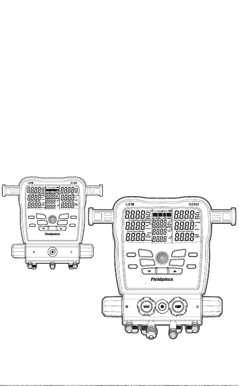
3 Port
Model SM382V
4 Port
Model SM482V
Page 2

Contents
Important Notice . . . . . . . .4
Class A2L/A2/A3 Refrigerant Safety Notice
Warnings
Quick Start . . . . . . . . . .5
What’s Included
Description . . . . . . . . . .6
Features
SM382V Front View
SM382V Rear View
SM482V Front View
SM482V Rear View
Display
Operation . . . . . . . . . 18
Buttons
Recent Refrigerants
LINK TOOL Select
N2 TEST Select (Pressure Test)
PIPE / AIR Select
T1-T2 / TSH / ODDB Select
Superheat (SH) and Subcooling (SC)
Target Superheat (TSH)
Deep Vacuum (SM382V & SM482V)
Test for Non-Condensables
Menu . . . . . . . . . . . 29
Data Logging
Auto Power O (APO)
Temperature Calibration (CalTemp)
ToolSet
Units
Vacuum Alarms
Backlight Timer
Advanced Pressure Calibration
Firmware View and Update
Restore User Settings
Delete Log File
Format Internal Flash Drive
Maintenance. . . . . . . . . 40
Cleaning
Battery Replacement
Using Dierent Refrigerants
Spare Parts
Hose Holder Replacement
Pipe Clamp Storage Arm Replacement
Valve and Knob Replacement
Specications . . . . . . . . 44
Temperature
Pressure
Deep Vacuum
Wireless Compatibility
Manifold Diagrams (SM382V & SM482V)
Certication and Module IDs . . . 47
Limited Warranty . . . . . . . 50
32
Page 3
Important Notice
!
This is not a consumer product. Only qualied
personnel trained in service and installation of
A/C and/or refrigeration equipment shall use
this product.
Read and understand this operator’s manual in
its entirety before using your SMAN® Refrigerant
Manifold to prevent injury or damage to you or
equipment.
Class A2L/A2/A3 Refrigerant
Safety Notice
Systems using class A2L (mildly ammable),
class A2 (flammable), or class A3 (highly
ammable) refrigerants can be tested safely ONLY
by qualied personnel explicitly trained in the use
and handling of those refrigerants. This manual
is in no way a replacement for proper training.
WARNINGS
Do not apply more than 870 psig to any port of the manifold.
Ground properly when testing A2L/A2/A3 (hydrocarbon) refrigerants.
Do not use in the vicinity of explosive substances.
Inhalation of high concentrations of refrigerant vapor can block oxygen to
the brain causing injury or death.
Refrigerant liquid can cause frostbite.
Follow all equipment manufacturer’s testing procedures above those in
this manual in regards to properly servicing their equipment.
Quick Start
1. Install the included six AA batteries into rear
battery compartment.
2. Press center blue button for 2 seconds to
turn on your new SMAN® manifold.
3. Connect your hoses and pipe clamps to the
SMAN® manifold and to the system.
4. View live pressures and temperatures.
5. Use arrow buttons to cycle through available
refrigerants and view calculations in real-time!
What’s Included
• SMAN® Refrigerant Manifold (3 Port), or
• SMAN® Refrigerant Manifold (4 Port)
• (1) ANC82 Padded, Easy-Open Case
• (2) TC24 Type K Pipe Clamp Thermocouples
• (1) ATA1 Type K Bead Thermocouple w/Clip
• (6) AA Alkaline Batteries
• (1) Year Warranty
• Operator’s Manual
Scan for more languages.
US, CA, MX EN, DE, FR, IT, ES, PT,
NL, SE, DK, FI
54
Page 4

Description
SMAN® Refrigerant Manifolds give you the trust
needed for doing the job right the rst time.
Your new Fieldpiece manifold has the protection
and long range wireless communication
demanded by professionals working in the eld.
The impact resistant housing seals and protects
from dust, bumps, and rain. Use the heavy
duty hook to hang it in your work vehicle while
protected by its easy-open padded soft case.
SMAN® is your testing hub at the jobsite. In
addition to the included thermocouples, you
can connect wirelessly to psychrometers, pipe
clamps, and even a refrigerant scale. For example,
assign one psychrometer (model JL3RH) to
return air and another to supply air to view live
temperature split across the evaporator.
View it all clearly, in any lighting condition, on
the extra large LCD or remotely on your mobile
device. A rolling list of your 10 most recently
used refrigerants, indicated by a , is stored
at the top of the main refrigerant list for quick
selection.
Verify proper charge by comparing actual
superheat (SH) with target superheat (TSH). A
thermocouple is included for wired outdoor dry
bulb. You can link optional wireless tools for live
indoor wet bulb and outdoor dry bulb!
Pressure sensors automatically compensate
for altitude and weather changes. Use the
internal vacuum gauge for fast and convenient
monitoring of your evacuations, or link to a
wireless vacuum gauge for more control.
Features
Job Link® System
- Long Wireless Range (1000 feet / 305 meters)
- Connect to Your Mobile Device (page 43)
- Connect Job Link Tools (page 43)
Real-time Calculations
- Superheat and Subcooling
- Vapor Saturation and Liquid Saturation
- Target Superheat (requires model JL3RH for real-time)
- T1-T2
(3) Type K Thermocouple Jacks
- Suction Line
- Liquid Line
- Outdoor Ambient
Robust Port Design
- SM382V: (3) 1/4”
- SM482V: (3) 1/4” + (1) 3/8”
Built-in Vacuum Gauge with Graphic Indicators
Nitrogen Test (Tightness Test)
Recent Refrigerant List
Sealed Sight Glass
Heavy Duty Rubberized Construction
Rugged Hanging Hook
Operation in the Rain (IP55)
Data Logging with USB-C Export
7
Page 5
ZERO PRESSURE
TARE SCALE
T1-T2 / TSH / ODDB
AIR PARAMETER
SMAN Refrigerant Manifold + Vacuum Gauge
PIPE / AIR
SELECT
N TEST
VAC ALARM
MENU
EXIT STOP / EXIT
LINK TOOL
Hrs
#
Sec
RET
SUP
LLT
SLT
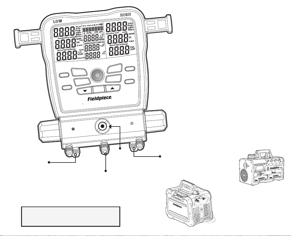
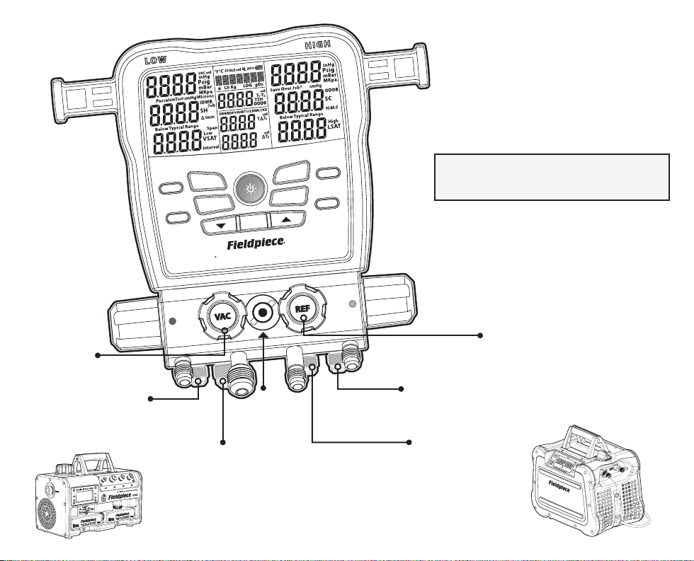
Suction Line
Port Valve
Suction
Line Port
Refrigerant Port
Connect to a refrigerant cylinder
directly, to a recovery machine,
or to a vacuum pump.
NOTE: Use the front ports as Hose Holders
and back ports as Manifold ports.
Sight
Glass
Pipe Clamp
Storage Arms
Liquid Line
Port Valve
Liquid
Line Port
SM382V Front View
Fieldpiece Vacuum Pumps
available in 6 CFM, 8 CFM
& 10 CFM models
(sold separately)
Fieldpiece Recovery
Machine model MR45
(sold separately)
98
Page 6
5678
LLT
TYPE K
ODDB
TYPE K
SLT
TYPE K
MAXIMUM PRESSURE 870 PSI (60 BAR).
GROUND PROPERLY FOR A2L/A2/A3 REFRIGERANTS.
PROPER TRAINING REQUIRED.
ID OF MODULE CONTAINED
FCC ID: 2ALHR0008
IC: 22518-BT008
US PAT.
fieldpiece.com/patents
SM382V
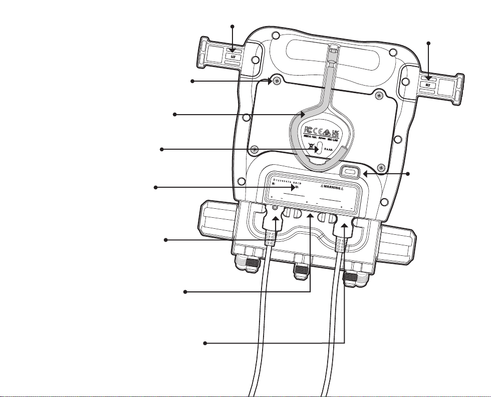
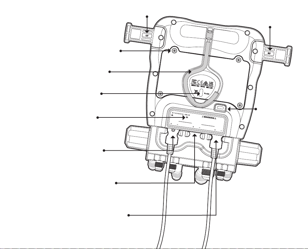
SM382V Rear View
Battery Cover Screws
Steel Hanging Hook
Battery Door Finger Pull
(LLT ) Pipe Clamp
Storage Arm
(SLT ) Pipe Clamp
Storage Arm
4 Digit Job Link® System ID
Use when connecting to the Job Link
Mobile App for testing and reporting
(LLT ) Liquid Line
Thermocouple Jack
Shown not inserted enough past the bumpers
(ODDB) Outdoor
Thermocouple Jack
Shown without thermocouple
(SLT ) Suction Line
Thermocouple Jack
Shown fully inserted & locked into the bumpers
USB-C Port
Access with removable
rubber cover. Ensure it
is on to maintain IP-55
water resistant rating.
Thermocouple
Bumpers
Bumpers help secure
thermocouple plugs.
Pipe clamp thermocouples
have indents on the plug
that line up with the bumper
when fully inserted.
1110
Page 7
Hrs
#
Sec
RET
SUP
LLT
SLT
ZERO PRESSURE
TARE SCALE
T1-T2 / TSH / ODDB
AIR PARAMETER
SMAN Refrigerant Manifold + Vacuum Gauge
PIPE / AIR
SELECT
N TEST
VAC ALARM
MENU
EXIT STOP / EXIT
LINK TOOL
Hrs
#
Sec
RET
SUP
LLT
SLT
Suction Line
Port Valve
Vacuum
Port Valve
Suction
Line Port
Sight
Glass
Vacuum Port
Large port matches perfectly with
Fieldpiece Vacuum Pumps
Pipe Clamp
Storage Arms
SM482V Front View
NOTE: Use the front ports as Hose Holders
and back ports as Manifold ports.
Liquid Line
Port Valve
Refrigerant Port Valve
Liquid
Line Port
Refrigerant Port
Connect to a refrigerant
cylinder directly, or to
a recovery machine like
Fieldpiece model MR45
1312
Page 8
ZERO PRESSURE
TARE SCALE
SMAN Refrigerant Manifold + Vacuum Gauge
MENU
EXIT STOP / EXIT
LINK TOOL
Hrs
#
Sec
RET
SUP
LLT
SLT
5678
LLT
TYPE K
ODDB
TYPE K
SLT
TYPE K
MAXIMUM PRESSURE 870 PSI (60 BAR).
GROUND PROPERLY FOR A2L/A2/A3 REFRIGERANTS.
PROPER TRAINING REQUIRED.
ID OF MODULE CONTAINED
FCC ID: 2ALHR0008
IC: 22518-BT008
US PAT.
fieldpiece.com/patents
SM482V
SM482V Rear View
Battery Cover Screws
Steel Hanging Hook
Battery Door Finger Pull
(LLT ) Pipe Clamp
Storage Arm
(SLT ) Pipe Clamp
Storage Arm
4 Digit Job Link® System ID
Use when connecting to the Job Link
Mobile App for testing and reporting
(LLT ) Liquid Line
Thermocouple Jack
Shown not inserted enough past the bumpers
(ODDB) Outdoor
Thermocouple Jack
Shown without thermocouple
Shown fully inserted & locked into the bumpers
(SLT ) Suction Line
Thermocouple Jack
USB-C Port
Access with removable
rubber cover. Ensure it
is on to maintain IP-55
water resistant rating.
Thermocouple
Bumpers
Bumpers help secure
thermocouple plugs.
Pipe clamp thermocouples
have indents on the plug
that line up with the bumper
when fully inserted.
1514
Page 9
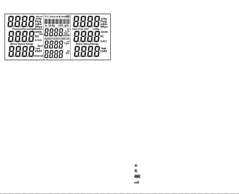
Display
Hrs
#
Sec
RET
SUP
LLT
SLT
°F: Temperature (Fahrenheit)
°C: Temperature (Celsius)
Psig: Pressure (pounds/in2)
Bar: Pressure / Negative Pressure
MPa: Pressure (megapascals)
kPa: Pressure (kilopascals)
inHg: Negative Pressure (inches of mercury)
cmHg: Negative Pressure (centimeters of mercury)
Microns: Vacuum (microns of mercury)
Pascals: Vacuum
mBar: Vacuum (millibar)
mTorr: Vacuum (millitorr)
Torr: Vacuum (equivalent to mmHg)
Δ/min: Vacuum Rate (dierential per minute)
H:M:S: Hours:Minutes or Minutes:Seconds
SH: Superheat (suction line - vapor saturation)
SC: Subcooling (liquid saturation - liquid line)
VSAT: Vapor Saturation Temperature (from P-T chart)
LSAT: Liquid Saturation Temperature (from P-T chart)
TSH: Target Superheat (calculated from IDWB and ODDB)
T1-T2: Measurement Dierential
SLT : Suction Line Temperature (low side)
LLT : Liquid Line Temperature (high side)
ODDB: Outdoor Dry Bulb Temperature
IDWB: Indoor Wet Bulb Temperature
LOG: Data Logging in Progress
Job: Job Slot (1-9) of Data Log
Span: Hours (Hrs) of Data Logging
Interval: Seconds (Sec) Between Logged Measurements
Low: Vac Alarm Lowest Micron Level
High: Vac Alarm Highest Micron Level
RET: Return Psychrometer
SUP: Supply Psychrometer
DB: Dry Bulb from Psychrometer
WB: Wet Bulb from Psychrometer
DP: Dew Point from Psychrometer
%RH: Relative Humidity from Psychrometer
BTU/LBM: Enthalpy from Psychrometer (BTU per pound mass)
KJ/KG: Enthalpy from Psychrometer (kilojoules per kilogram)
TΔT : Target Dry Bulb Split from Psychrometers (Target Delta T)
ΔT: Dry Bulb Split from Psychrometers (Delta T)
Lb: Pounds (from wireless scale)
Oz: Ounces (from wireless scale)
Kg: Kilograms (from wireless scale)
g: Grams (from wireless scale)
VAC: Wireless Vacuum Gauge Connected
SCALE: Wireless Scale Connected
APO: Auto Power O Enabled
: Top 10 Refrigerant Selected
: Speaker Turned O
: Battery Life Remaining
: Wireless Signal Strength
1716
Page 10

Operation
Buttons
A beep sounds when a button is pressed. A
double beep sounds when a button is pressed
and the function is not possible at that time. The
speaker can be muted altogether (page 29).
Press 2 sec to toggle power. Press to toggle backlight.
Cycle through refrigerants, change values or vacuum views.
SELECT: Conrm a changed value or activate a VAC ALARM (page 24).
MENU: Enter the menu (page 29) or EXIT a mode.
LINK TOOL: Connect wireless tools (page 19).
N2 TEST: For Nitrogen pressure tests (page 20).
PIPE / AIR: Display SLT/LLT or various return and supply air
measurements from optional psychrometers (page 21).
TARE SCALE: Press 2 sec to zero (tare) weight from a wireless scale.
ZERO PRESSURE: Press 2 sec to zero the displayed pressures.
AIR PARAMETER: Toggle to display DB, WB, DP, %RH, BTU/LBM,TΔT
& ΔT (page 23).
T1-T2/TSH/ODDB: Display T1-T2, TSH, or ODDB (page 21).
Recent Refrigerants (
A rolling list of your 10 most recent refrigerants,
indicated by a
When you power o your manifold, the current
refrigerant is added automatically to this dynamic
list of 10.
, is stored above the main list.
)
LINK TOOL
Assign wireless Job Link® System tools to
core manifold measurements such as pipe
temperature or to broader measurements such
as refrigerant weights and psychrometrics.
1. Press LINK TOOL to search for supported Fieldpiece wireless tools.
2. Turn on any wireless sources you want to assign.
If your Job Link® System tool has a selector switch, ensure it’s set to
match the measurement.
3. Use ARROWS to auto search yes or no.
Job Link® System tools are displayed by their 4 digit ID, usually found
on the back of the tool.
4. Press SELECT to select and return to the list of measurements.
• Press MENU to exit at any time. If changes were made, choose
whether or not you want to save changes.
• Most Job Link® System tools have a switch that selects a side of the
system. Set it to match the measurement you’re assigning it to.
• A wireless Return psychrometer is assigned to both Return air and
IDWB (page 23) when selected.
NOTE: When adding JL3PC or JL3LC pipe clamps, you will need to
disconnect the TC24 Type-K pipe clamps from the manifold.
1918
Page 11

N2 TEST (Pressure Test)
After working on a refrigerant-side component
of an emptied system, it’s a good idea to
pressurize the system with dry nitrogen and
check for pressure drops before evacuation.
1. Pressurize the system with dry nitrogen. Pressure levels vary with
the equipment you’re testing. Always check with the manufacturer.
2. Connect the low side (suction line) port to the system and wait for
the pressure to stabilize. You can connect the high side (liquid line)
as well to help monitor stability, but the pressure dierential (P.diF)
calculation is only using the low side sensor.
3. Attach SLT clamp to the pipe you’re going to pressurize.
This temperature is used to compensate for any temperature changes
between the start and end of the test.
Select “
Comp. OFF
compensation.
4. Press N2 TEST to prepare test.
5. Press N2 TEST to start the test.
The stopwatch starts.
Real-time compensated pressure change is labeled Δ.
Real-time temperature is labeled SLT.
Real-time temperature change is labeled ΔT.
6. Press N2 TEST to stop the test.
The stopwatch, Δ, and ΔT freeze.
If Δ is negative, there may be a leak in the system.
If Δ is positive, SLT or nitrogen temperature may be unstable.
High and low side pressures and SLT continue to display, but they are
no longer being used.
7. Press N2 TEST to exit the test.
• To save battery life, the screen will turn o after 3 hours of testing,
but will continue to test. Press any button to turn the screen on.
” in
MENU
to deactivate temperature
PIPE / AIR
Press PIPE / AIR to display various calculations
and measurements from Job Link® System
psychrometers you’ve assigned (page 19). The
parameter is briey shown when pressed, then
shown at the top of the LCD.
Press PIPE / AIR for >1 second to view SLT/LLT.
SLT : Live reading of suction line temperature.
LLT : Live reading of liquid line temperature.
RET: Live reading from return air psychrometer.
SUP: Live reading from supply air psychrometer.
TΔT : Live target dry bulb split from psychrometers.
ΔT: Live actual dry bulb split from psychrometers.
T1-T2 / TSH / ODDB
Press T1-T2 / TSH / ODDB to cycle through
ODDB (outdoor dry bulb), TSH (target superheat),
and T1-T2 (middle display - bottom display).
ODDB: Live reading of the rear ODDB thermocouple jack. ODDB does
not show if set to manual value (page 23).
TSH: Live target superheat calculated from ODDB and IDWB. Each of
these measurements can be live or manually entered (page 21).
T1-T2: Live simple subtraction of the bottom display (T2) from the
middle display (T1). With SLT and LLT showing, you can check for a
temperature drop across a lter drier. With RET and SUP showing,
you can check the eect of the indoor unit. With TΔT and ΔT showing,
you can see how close the actual ΔT is to the target.
2120
Page 12

Superheat (SH) and Subcooling (SC)
Superheat is the amount of heat added to
refrigerant after changing to a vapor in the
evaporator. Subcooling is the amount of heat
removed from refrigerant after changing to a
liquid in the condenser. View both live at the
same time!
1. Use ARROWS to select the system refrigerant.
2. Close all manifold valves.
3. Connect EPA approved refrigerant hoses to LOW and HIGH side ports.
4. Connect your supported wireless pipe clamps, or fully plug pipe clamp
thermocouples into SLT and LLT rear jacks. See LINK TOOL on page 19.
5. Hand tighten both the LOW side hose to suction line service port and
the HIGH side hose to the liquid line service port.
6. Clamp the SLT thermocouple to the suction line between the
evaporator and compressor, at least 6 inches from the compressor.
7. Clamp the LLT thermocouple to the liquid line between the condenser
and metering device, as close to the service port as possible.
8. Purge hoses as you open HIGH and LOW manifold valves.
9. View superheat and subcooling in real-time.
• Ensure system has stabilized before using superheat or subcooling to
adjust the charge of the system.
• To add or remove refrigerant connect the tank/cylinder/machine to
the REF port. Use the manifold valves to precisely charge or recover
refrigerant as needed. Follow recommended charging or recovery
practices from equipment manufacturer and training.
• When superheat and/or subcooling cannot be calculated, “- - - - ”
will be displayed. If superheat and/or subcooling is negative, “Below
Typical Range” will show. In rare cases this is normal, but usually a
thermocouple is disconnected or the selected refrigerant is incorrect.
Target Superheat (TSH)
Compare target superheat (TSH) to actual
superheat (SH) when charging fixed orifice
air conditioning systems. TSH is continually
calculated from indoor wet bulb (IDWB) and
outdoor dry bulb (ODDB) temperatures.
IDWB: By default, this is a manually set value of 60.0°F.
For a live measurement, assign the optional model JL3RH wireless
psychrometer. See LINK TOOL on page 19.
ODDB: By default, this is the live measurement of the ODDB
thermocouple jack. If you prefer a static measurement, assign a
manual value. NOTE: Use your wireless psychrometer (JL3RH or
PRH3) by pressing MENU > ToolSet > Outdoor (ODDB ashing) >
SELECT > Arrows between Type K / Manual / ID-#### > SELECT.
1. Connect the included type K bead thermocouple to the ODDB
thermocouple jack. Use the alligator clip to locate the bead in a
shaded area of the condenser to measure the temperature of air
entering the condenser.
2. Use ARROWS to scroll through detected measurement sources.
Job Link® System tools are displayed by their 4 digit ID, usually found on
the back of the tool.
3. Turn on any wireless sources you want to assign.
If your Job Link® System tool has a selector switch, ensure it’s set to
match the measurement.
4. Press SELECT to select and exit or go to next until complete.
5. Press T1-T2 / TSH / ODDB until ODDB is displayed.
If you changed ODDB to a manually set value, it will be used to calculate
TSH but will not be displayed.
6. Measure IDWB after the lter, just in front of the indoor coil. If a
psychrometer is assigned, you can press AIR PARAMETER until wet
bulb is displayed to verify the measurement.
7. Press T1-T2 / TSH / ODDB until TSH is displayed.
2322
Page 13
ZERO PRESSURE
TARE SCALE
T1-T2 / TSH / ODDB
AIR PARAMETER
SMAN Refrigerant Manifold + Vacuum Gauge
PIPE / AIR
SELECT
N TEST
VAC ALARM
MENU
EXIT STOP / EXIT
LINK TOOL
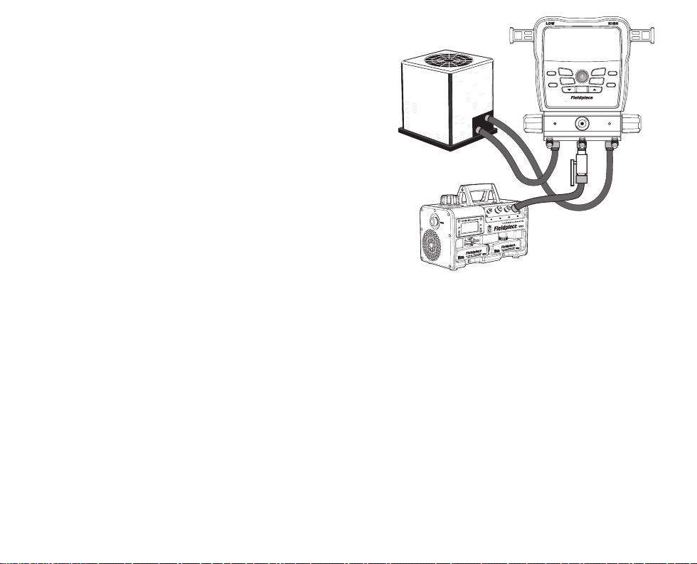
Deep Vacuum - Model SM382V
Follow recommended evacuation practices
from equipment manufacturer and training.
Alarms can be adjusted in the MENU (page 34).
1. Close all manifold valves.
2. Setup your tools and equipment (see diagram).
Connect manifold 1/4” HIGH port to liquid line service port.
Connect manifold 1/4” LOW port to suction line service port.
Connect manifold 1/4” middle port to vacuum pump with a shuto valve in
between.
3. Turn on your vacuum pump.
4. Open shuto valve.
The vacuum sensor is now exposed to your pump, but it will not display until
HIGH/LOW manifold valves are opened. This ensures the measurement is of the
system and not just the manifold.
5. Open HIGH and LOW manifold valves.
6. Press VAC ALARM to activate the low alarm. See details on page 34
The stopwatch starts. The rate of change is displayed in units per minute. Press
ARROWS
to switch between Rate Meter and Bar Graph views. The smaller the
rate of change, the closer you are to stabilization. You may need to improve your
setup if rate slows well before reaching your desired vacuum (see Tips for Better
Evacuations). Note: The Rate Meter shows vacuum progress and eliminates
uncertainty with a dynamic view. Bars displayed on the left side shows
decreasing vacuum, bars in the center show a stable vacuum, and bars on the
right side shows increasing vacuum. The Bar Graph is static and nonlinear for
increased resolution at deeper vacuums.
7. Once the low alarm level is reached, the backlight blinks and alarm sounds.
Press any button (other than SELECT) to silence alarm.
8. Close your shuto valve between the middle port and pump to block the
pump.
Do not close HIGH and LOW valves or you’ll block the system and measure just
the manifold!
9. Turn o your vacuum pump.
10. Press VAC ALARM to activate the high alarm and start the stopwatch.
11. Once the high alarm level is reached, the backlight blinks, alarm sounds, and
the stopwatch stops. Press any button (other than SELECT) to silence alarm.
12. Close HIGH and LOW manifold valves.
The vacuum sensor is now blocked from the system (page 44).
.
TARE SCALE
LINK TOOL
ZERO PRESSURE
SMAN Refrigerant Manifold + Vacuum Gauge
AIR PARAMETER
PIPE / AIR
T1-T2 / TSH / ODDB
SELECT
VAC ALARM
N TEST
MENU
EXIT STOP / EXIT
Tips for Better Evacuations
• Remove Schrader valve cores & depressors with a core removal tool.
• Use shortest vacuum rated hoses with largest diameter available.
• Do not evacuate through hoses with low loss ttings.
• Inspect the rubber seals at both ends of your hoses for damage.
• Apply a light amount of vacuum oil to the service port ttings
before attaching hoses to help maintain a vacuum-tight seal.
• Change pump oil before and during the job. Change pump oil onthe-y without losing vacuum with Fieldpiece vacuum pumps.
• When the vacuum pump is blocked, a slow rise that stabilizes may
signify moisture is still present in the system. A continuous rise to
atmosphere indicates a leak. Check hoses, tools, or the system itself.
• Measurements are less representative of the entire system when
the vacuum pump is on because pumping creates a pressure
gradient. Block the pump and allow the system to stabilize before
assuming the measurement is of the entire system.
2524
Page 14
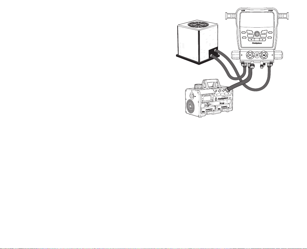
Deep Vacuum - Model SM482V
Follow recommended evacuation practices
from equipment manufacturer and training.
Alarms can be adjusted in the MENU (page 34).
1. Close all manifold valves.
2. Setup your tools and equipment (see diagram).
Connect manifold 1/4” HIGH port to liquid line service port.
Connect manifold 1/4” LOW port to suction line service port.
Connect manifold 3/8” VAC port to vacuum pump.
3. Turn on your vacuum pump.
4. Open VAC valve.
The vacuum sensor is now exposed to your pump, but it will not display until
HIGH/LOW manifold valves are opened. This ensures the measurement is of the
system and not just the manifold.
5. Open HIGH and LOW manifold valves.
6. Press VAC ALARM to activate the low alarm. See details on page 34
The stopwatch starts. The rate of change is displayed in units per minute. Press
ARROWS
to switch between Rate Meter and Bar Graph views. The smaller the
rate of change, the closer you are to stabilization. You may need to improve your
setup if rate slows well before reaching your desired vacuum (see Tips for Better
Evacuations). Note: The Rate Meter shows vacuum progress and eliminates
uncertainty with a dynamic view. Bars displayed on the left side shows
decreasing vacuum, bars in the center show a stable vacuum, and bars on the
right side shows increasing vacuum. The Bar Graph is static and nonlinear for
increased resolution at deeper vacuums.
7. Once the low alarm level is reached, the backlight blinks and alarm sounds.
Press any button (other than SELECT) to silence alarm.
8. Close VAC valve to block the pump.
Do not close HIGH and LOW valves or you’ll block the system and measure just
the manifold!
9. Turn o your vacuum pump.
10. Press VAC ALARM to activate the high alarm and start the stopwatch.
11. Once the high alarm level is reached, the backlight blinks, alarm sounds, and
the stopwatch stops. Press any button (other than SELECT) to silence alarm.
12. Close HIGH and LOW manifold valves.
The vacuum sensor is now blocked from the system (page 44).
.
TARE SCALE
LINK TOOL
ZERO PRESSURE
SMAN Refrigerant Manifold + Vacuum Gauge
AIR PARAMETER
PIPE / AIR
T1-T2 / TSH / ODDB
SELECT
VAC ALARM
N TEST
MENU
EXIT STOP / EXIT
Tips for Better Evacuations
• Remove Schrader valve cores & depressors with a core removal tool.
• Use shortest vacuum rated hoses with largest diameter available.
• Do not evacuate through hoses with low loss ttings.
• Inspect the rubber seals at both ends of your hoses for damage.
• Apply a light amount of vacuum oil to the service port ttings
before attaching hoses to help maintain a vacuum-tight seal.
• Change pump oil before and during the job. Change pump oil onthe-y without losing vacuum with Fieldpiece vacuum pumps.
• When the vacuum pump is blocked, a slow rise that stabilizes may
signify moisture is still present in the system. A continuous rise to
atmosphere indicates a leak. Check hoses, tools, or the system itself.
• Measurements are less representative of the entire system when
the vacuum pump is on because pumping creates a pressure
gradient. Block the pump and allow the system to stabilize before
assuming the measurement is of the entire system.
2726
Page 15

Test for Non-Condensables
If head pressure seems high even after cleaning
coils, optimizing airflow, and other routine
maintenance, you may have non-condensables
trapped in the system or a low refrigerant
charge. Non-condensables can reduce eciency,
performance, and put extra stress on system
components. Non-condensables can enter the
system in many ways, and your initial system
service may be following years of poor service
that introduced the non-condensables.
1. Use ARROWS to select the system refrigerant.
2. Unpower the compressor, but allow the condenser fan to run.
3. Connect high side port to the system to view system pressure.
4. Clamp one thermocouple to the discharge line.
5. Clamp the other thermocouple to the liquid line.
6. Clip the ODDB thermocouple to measure the air entering the
condenser.
7. Monitor all three temperatures until they all stabilize and show the
same value.
8. View the subcooling (SC) calculation on the display.
The closer SC is to 0.0°, the fewer non-condensables are trapped.
Depending on the system, a negative SC may suggest a need to
recover, evacuate, and charge with virgin refrigerant.
Menu
Press MENU to enter the menu where most
settings are located. Use arrows to scroll through
the menu and press SELECT to select one of the
below menu items. NOTE: Starts from MENU
function most recently entered.
LogData: Enter data logging setup mode (page 30).
(StopLog): If data logging, stop the log (page 30).
AutoO: Enter auto o timer setup mode (page 31).
CalTemp: Enter calibration mode for Type K jacks (page 32).
Disable: Select to turn OFF wireless functionality.
Enable: Select to turn ON wireless functionality.
ToolSet: Enter wireless source setup mode (page 33).
Units: Enter units setup mode (page 34).
Vac Alarms: Enter vacuum alarm setup mode if gauge is assigned
(page 34).
Mute: If unmuted, mute the speaker.
(Unmute): If muted, unmute the speaker.
Backlight Timer: Enter backlight timer setup mode (page 35).
Enable N2 Temp. Comp.: Enable N2 Test Parameters if OFF.
(Disable N2 Temp. Comp.): Disable N2 Test Parameters if ON.
Adv Pressure Cal: Enter advanced calibration mode for pressure
sensors (page 36).
F Ware: Enter rmware view and update mode (page 38).
Language: Select your language (English, German, French,
Portuguese, Italian, Spanish, Danish, Dutch, Finnish, Swedish,
Turkish, or Norwegian).
Restore Settings: Enter restore factory settings mode (page 38).
(Delete Log File): If a Job .csv log le is saved to the internal ash
drive, enter delete log le mode (page 39).
Format Drive: Enter format drive mode (page 39).
2928
Page 16

Data Logging
Log measurements and resulting calculations,
such as Superheat, at chosen spans and intervals.
Save up to 9 Jobs (logs) to the internal ash drive.
Auto Power O (APO)
To save battery life, your SMAN® manifold
automatically powers o after a set time of no
button presses.
MENU/LogData
1. Use ARROWS to scroll through Jobs.
The display will alternate between the % free space on the drive and
the % of space the chosen Job uses.
2. Press SELECT to select.
If a Job already exists in that slot, use ARROWS then SELECT to choose
whether or not you want to save over that Job.
3. Use ARROWS to set the Span (total time).
It’s a good idea to use new batteries if setting up a long span. If
batteries run out during a Job, the log will automatically stop and
save, then the SMAN® manifold will turn o.
4. Press SELECT to select.
5. Use ARROWS to set the Interval (time between measurements).
6. Press SELECT to select and begin logging data until the Span ends.
LOG will blink to indicate the log is still active.
• Press MENU to exit setup at any time.
• Press MENU and select StopLog to stop the Job and return to
standard operation. The Job will be saved.
• To save battery life, the screen will turn o after 3 hours of logging,
but will continue to log. Press any button to turn the screen on.
• Some buttons and features (including auto power o) are disabled
until the Job ends.
• Jobs are saved as .csv les.
• Connect to your computer via the USB-C port under the removable
rubber cover. View its internal ash drive just like any other USB
drive.
MENU/AutoO
1. Use ARROWS to scroll through times (default is 30 min).
2. Press SELECT to select and exit. If changes were made, choose
whether or not you want to save changes.
• Press MENU to exit at any time. If changes were made, choose
whether or not you want to save changes.
• APO is automatically disabled when in Deep Vacuum, N2 Test,
Firmware update and data logging modes.
3130
Page 17

Temperature Calibration (CalTemp)
Thermocouples (T/C) are not calibrated
directly. Instead, each T/C jack (LLT, ODDB, SLT)
must be calibrated to the particular T/C that
is plugged into it. Though it’s possible for a
calibration to hold for years, it’s best practice to
calibrate regularly if only to verify accuracy.
Calibration is quick and easy, requiring just a
known temperature to calibrate to. Ice water is
the recommended medium for in-eld calibration
due to known temperature (32.0 F, 0.0 C) and
ready availability.
MENU/CalTemp
1. Stabilize a large cup of ice water by stirring. Pure, distilled water
will be the most accurate.
2. Immerse the sensing end of the thermocouple in the ice water.
3. Use ARROWS to select the temperature you want to calibrate
(ODDB, SLT, or LLT).
4. Press SELECT to select.
5. Use ARROWS to adjust the temperature to match 32.0°F (0.0°C)
making sure the ice water is continually stirred. The calibration
range is limited to ±7°F (±3.8°C) in order to help prevent mistakes.
6. Press SELECT to save and return to the list of temperatures.
• Press MENU to exit at any time. If changes were made, choose
whether or not you want to save changes.
• If you have a wireless thermocouple (model JL3PC) assigned and
wireless is on, calibration is for the wireless thermocouple.
• Calibration of a wireless thermocouple (model JL3PC) does not
override a wired thermocouple calibration. You can switch between
wired and wireless without having to recalibrate.
ToolSet
Assign wireless Job Link® System tools to
core manifold measurements such as pipe
temperature or to broader measurements such
as refrigerant weights and psychrometrics.
Wireless OFF: Wireless is disabled by default. Line temperatures
(SLT and LLT) are automatically assigned to their type K jacks.
Wireless ON: SLT and LLT type K jacks DO NOT override an
assigned wireless source. If wireless clamps are linked, the SLT and
LLT ports are disabled.
MENU/ToolSet
1. Use ARROWS to scroll through the list of measurements.
2. Press SELECT to select.
3. Turn on any wireless sources you want to assign.
If your Job Link® System tool has a selector switch, ensure it’s set to
match the measurement.
4. Use ARROWS to scroll through detected measurement sources.
Job Link® System tools are displayed by their 4 digit ID, usually found
on the back of the tool.
5. Press SELECT to select and return to the list of measurements.
• Press MENU to exit at any time. If changes were made, choose
whether or not you want to save changes.
• Most Job Link® System tools have a switch that selects a side of the
system. Set it to match the measurement you’re assigning it to.
• Depending on the wireless tool, select Unlink, Type K, or
Onboard to set a source to its factory default source. This is useful
when you want to use a previously assigned tool at the job site, but
do not want to use it with the SMAN® manifold.
• A wireless Return psychrometer is assigned to both Return air and
IDWB (page 23) when selected.
3332
Page 18

Units
Each measurement can have its own unit of
measure.
Backlight Timer
The backlight turns o automatically after a set
time of no button presses.
MENU/Units
1. Use ARROWS to scroll through the list of measurements.
2. Press SELECT to select.
3. Use ARROWS to scroll through units of measure.
4. Press SELECT to select and return to the list of measurements.
• Press MENU to exit at any time. If a change was made before
pressing SELECT, choose whether or not you want to save the change.
Vacuum Alarms
Set high and low vacuum alarms so you know
when you’ve reached an appropriate vacuum
(Low) and time how long it takes to rise after
blocking the pump from the system (High).
MENU/Vac Alarms
1. Use ARROWS to toggle between high and low alarm.
2. Press SELECT to select.
3. Use ARROWS to adjust the alarm trigger in 25 micron increments.
4. Press SELECT to select and exit or go to next.
• Press MENU to exit at any time. If changes were made, choose
whether or not you want to save changes.
• The low alarm cannot go higher than the high alarm.
• The high alarm cannot go lower than the low alarm.
• Press SELECT (ALARM) while in deep vacuum to activate the next
alarm (None >> Low >> High >> None).
MENU/Backlight Timer
1. Use ARROWS to scroll through times (default is 2 min).
2. Press SELECT to select and exit. If changes were made, choose
whether or not you want to save changes.
• Press MENU to exit at any time. If changes were made, choose
whether or not you want to save changes.
3534
Page 19

Advanced Pressure Calibration
Typical HVACR service does not require this
procedure, but you can occasionally calibrate the
pressure sensors to maintain highest accuracy.
It works by measuring the temperature of
virgin refrigerant (not recovered refrigerant) and
applying an oset to match the pressure to that
refrigerant’s P-T chart.
1. Calibrate a beaded thermocouple to the ODDB jack (page 32).
2. Store a virgin refrigerant cylinder, upright and untouched, in the
stable ambient environment for at least 24 hours.
3. Leaving the cylinder in the same place it was left to stabilize,
connect the cylinder to either the HIGH or LOW side port.
4. Close VAC and REF valves and cap the unused port.
If you don’t have caps with seals, you can connect both ends of a
refrigerant hose to the unused ports or hose seats. Some refrigerant
will remain in the hoses which you need to recover after calibration.
5. Use ARROWS to select the refrigerant type in the cylinder.
6. Use tape to attach the ODDB thermocouple bead halfway up the
cylinder to measure the temperature of the refrigerant.
7. Press T1-T2 / TSH / ODDB until ODDB is displayed.
8. Open both HIGH and LOW side manifold valves.
9. Open the refrigerant cylinder valve.
The pressure inside cylinder should now be displayed on both HIGH
and LOW side pressure sensors.
10. Allow the pressure readings and ODDB temperature to stabilize.
11. Press MENU.
12. Use ARROWS to show Adv Pressure Cal.
13. Press SELECT to initiate calibration of the pressure sensors.
14. Each pressure sensor will briey display “Good” if successful or “Err”
if unsuccessful, then return to normal operating mode.
Troubleshooting an “Err” message
1. Measured pressure was less than 10 psig.
• Refrigerant cylinder may be nearly empty.
• Valves may be closed.
2. Measured pressure was not within ±3psig of VSAT pressure on
the P-T chart.
• Thermocouple may not have been calibrated properly.
• Thermocouple may not have been attached properly to cylinder.
• Thermocouple may have not been connected to ODDB jack.
• Refrigerant cylinder pressure was unstable.
• Refrigerant cylinder temperature was unstable.
• Refrigerant selected did not match refrigerant in cylinder.
3736
Page 20

Firmware View and Update
Firmware often becomes available as new
refrigerants and features become available.
Before entering this mode, download from
www.fieldpiece.com and transfer from the
computer to the manifold via the USB-C port on
the rear of the manifold.
MENU/F Ware
1. View the rmware version on the top line, P/T chart on the
second line, and radio region on the bottom line.
2. If a new rmware le is found on the internal ash drive from the
USB-C transfer, the new version(s) will be shown. Using the arrows,
SELECT YES or NO, whether or not you want to update.
3. Once installation begins you will see a bar moving across the
screen. “donE” will appear and your SMAN® manifold will turn o
when nished.
• Press MENU to exit at any time before installation begins.
• During installation, buttons are disabled.
• User settings & log les are not deleted.
Restore User Settings
Restore factory default user settings when you
want a fresh start.
MENU/Restore Settings
1. Use ARROWS to select Yes or No.
2. Press SELECT to select and exit.
3. Press MENU to exit at any time. If changes were made, choose
whether or not you want to save changes.
• If you choose to restore, it may take a few seconds before returning
to standard operation.
Delete Log File
Clear up space by deleting old logs or just view
free space available.
MENU/Delete Log File
1. Use ARROWS to scroll through Jobs (logs). The display will alternate
between the % free space on the drive and the % of space the chosen
Job uses.
2. Press SELECT to select a Job to delete. Choose whether or not you
want to delete that Job.
3. If you choose to delete, it may take a few seconds to nish. If
no additional Jobs are found, the manifold returns to standard
operation.
• Press MENU to exit at any time.
Format Internal Flash Drive
Quickly clear up maximum space by
reformatting the internal ash drive. This deletes
everything on the drive including log files,
rmware update les, and any other les added
manually.
MENU/Format Drive
1. Use ARROWS to select Yes or No.
2. Press SELECT to select and exit.
• Press MENU to exit at any time.
• If you choose to format, it may take a few seconds before returning
to standard operation.
• User settings are not deleted.
3938
Page 21

Maintenance
Cleaning
Wipe with damp cloth to clean the exterior.
Do not use solvents.
Over time, the vacuum sensor of the SMAN
may become contaminated with dirt, oil, and
other contaminants. If you are frequently owing
refrigerant through the manifold and exposing
the vacuum sensor to this ow, we recommend
that users should ush or clean their manifold
every 2 to 4 weeks to extend the life of the SMAN
by avoiding contaminants from building up on
the sensor components.
1. Never use an object such as a cotton swab to clean the sensor, you
may cause damage to the sensor.
2. Open all valves and cap all the ports except for the VAC port on a
4-port manifold or the center port on a 3-port manifold. Turn the
manifold over such that the manifold ports (not hose holders) are
facing up.
3. Drop enough Isopropyl (rubbing) alcohol (minimum 70% alcohol
content) into the VAC/center port using an eye dropper or funnel so
that it can ush out contaminants. (Roughly 7 mL)
4. Cap o the VAC/center port and gently shake your SMAN while
upside down to clean sensor. (Approximately 30 to 60 seconds.)
5. Turn right side up. Uncap one of the ports and pour out the rubbing
alcohol. Uncap and open all ports to allow sensors to dry out.
Drying usually takes about an hour.
Battery Replacement
The batteries must be replaced when the
battery life indicator is empty. Once the batteries
are drained beyond operating voltage, “Low Bat”
briey appears and the manifold turns o.
Unscrew the 4 cover screws and pull out the
rear battery cover. Replace the 6 AA batteries and
properly dispose of the old ones.
Using Dierent Refrigerants
You can use dierent refrigerants, but be sure
to purge your manifold block and hoses with
nitrogen before connecting to a system with a
different refrigerant. Contamination can hurt
system performance and cause damage.
Spare Parts
RSM82H – SMx82V Hose Holder Replacement Kit – 1/4” + 5/16”
RSM82E – SMx82V Pipe Clamp Ear Replacement Kit
RSMANK6 – SMAN 2 Valve and Knob Kit
RSMANK8 – SMAN 4 Valve and Knob Kit
4140
Page 22

Hose Holder Replacement
Your manifold hose holders are 1/4” as the default.
If you want to change them to the 5/16” (silver color)
hose holders or replace a damaged 1/4” hose holder,
please complete the following.
1. Lay your manifold face up on a non-abrasive, at surface.
2. Insert a thin shafted, Phillips screwdriver into the desired hose holder. Turn
the screw counter clockwise to loosen and remove the 1/4” (brass color)
hose holder. Take care to not damage or strip the screw head.
3. Replace the sealing o-ring with a new o-ring. Ensure that the o-ring does
not block the threaded screw hole.
4. Insert the replacement hose holder and align it to the ats in the manifold
block so that the bottom of the tting is ush with the manifold block.
5. Insert a new screw into the replacement hose holder. Do NOT re-use the
old screw. Use your screwdriver to securely tighten. The provided screws
are pre-coated with threadlocker. Do NOT overtighten.
6. Store the 1/4” hose holder in a safe and secure place for future use.
Pipe Clamp Storage Arm
Replacement
Your pipe clamp storage arms can easily be replaced
if they become damaged or capped if unused.
1. Lay your manifold face down on a non-abrasive, at surface.
2. Using a Phillips screwdriver, loosen the screw by turning it counter
clockwise.
3. Discard the damaged storage arm and screw.
4. Select the correct side replacement, or cap (LLT or SLT), and slide in to
securely insert. Ensure it is ush with the manifold body.
5. Insert a new screw, use your screwdriver to securely tighten. Do NOT
re-use the old screw. Do NOT overtighten.
Valve and Knob Replacement
If you are experiencing vacuum leaks through
your valve(s), gauges are inaccurate, or there is
physical damage, please complete the following
to rebuild.
1. Lay your manifold face up on a non-abrasive, at surface.
2. On the valve(s) you are replacing, pry, lift and remove the knob’s label
to expose the knob’s screw.
3. With a Phillips screwdriver, turn the screw counter clockwise to loosen
and remove the knob. Do NOT re-use the old screw.
4. Using a 20 mm wrench, loosen the old valve by turning it counter
clockwise. Once loose, pull straight up to remove.
5. On the replacement valve, apply a thin layer of silicone grease to the
o-rings. Push the valve back in, tighten by hand and complete with
your wrench until tight. Do NOT overtighten.
desired.
6. Put on the new knob and twist until tight. Use the new screw and turn
clockwise until tight onto the valve stem.
7. Stick on the correct replacement label depending on which valve you
replaced.
8. Depending on how many valves you are replacing, repeat steps 2-7 as
needed.
Use a threadlocker if
Use a threadlocker if desired.
4342
Page 23

Specications
Display: LCD (5 inches diagonal)
Backlight: Blue (adjustable duration)
Low Battery Indication: is displayed when the battery voltage
drops below the operating level.
Over Range Display: OL for pressure, - - - - for temperature
Auto Power O: 30 minutes of inactivity (adjustable)
Maximum Manifold Pressure: 870 Psig (5998 kPa)
Battery Type: 6 x AA alkaline
Battery Life: 405 hours typical
(without vacuum, backlight, and wireless)
Radio Frequency: 2.4 GHz
Wireless Range: 1000 feet (305 meters) line of sight.
Distance decreases through obstructions.
Data Port: USB-C (for extracting data logs or updating rmware)
Operating Environment: 14°F to 122°F (-10°C to 50°C) at <75% RH
Storage Environment: -4°F to 140°F (-20°C to 60°C) at <80% RH
(with battery removed)
Temperature Coecient: 0.1 x (specied accuracy) per 1.8°F (14°F
to 64°F, 82°F to 122°F), per °C (-10°C to 18°C, 28°C to 50°C)
Weight: SM382V: 3.31 lbs (1.5 kg); SM482V: 3.97 lbs (1.8 kg)
Water Resistant: Tested to IP55
US Patent: www.eldpiece.com/patents
Refrigerants: New refrigerants are continually being added so be
sure to visit www.fieldpiece.com for the latest rmware.
R11
R115
R290
R407A
R414A
R422A
R438A
R458A
R600
R12
R116
R401A
R407C
R414B
R422B
R448A
R500
R600A
R13
R123
R401B
R407F
R416A
R422C
R449A
R501
R601
R22
R124
R402A
R407H
R417A
R422D
R450A
R502
R601A
R23
R125
R402B
R408A
R417C
R424A
R452A
R503
R744*
R32
R134A
R403B
R409A
R420A
R427A
R452B
R507A
R1233ZD
R113
R236FA
R404A
R410A
R421A
R428A
R453A
R508B
R1234YF
R114
R245FA
R406A
R413A
R421B
R434A
R454B
R513A
R1234ZE
*Maximum pressure: 870 Psig (6000 kPa)
Temperature
Sensor Type: Type K thermocouple
(nickel chromium/nickel aluminum)
Jack Type: (3) Type K thermocouple
Range: -50°F to 257°F (-46°C to 125°C), limited by the thermocouple
specication. Display range is -95°F to 999.9°F (-70°C to 537.0°C).
Resolution: 0.1°F (0.1°C)
Accuracy: Shown accuracies are after eld calibration.
±(1.0°F) -95°F to 200°F, ±(2.0°F) 200°F to 999.9°F;
±(0.5°C) -70°C to 93°C, ±(1.0°C) 93°C to 537.0°C
Pressure
Sensor Type: Absolute pressure sensors
Port Type: SM382V: (3) 1/4” standard SAE male are ttings, or
SM482V: (1) 3/8” and (3) 1/4” standard SAE male are ttings
Pressure Range and Units: 870 Psig (English), 60.00 Bar (Metric),
6.000 MPa (Metric), and 6000 kPa (Metric)
Negative Pressure Range and Units:
29 inHg (English), 74 cmHg (Metric), 0.98 Bar (Metric)
Resolution: 0.1 Psig; 0.01 Bar; 0.001 MPa; 1 kPa; 0.1 inHg; 1 cmHg
Negative Pressure Accuracy:
29 inHg to 0 inHg: ±0.2 inHg;
74 cmHg to 0 cmHg: ±1 cmHg
0.98 Bar to 0 Bar; ±0.01 Bar
Pressure Accuracy:
0 Psig to 200 Psig: ±1 Psig;
200 Psig to 870 Psig: ±(0.3% of reading + 1 Psig);
0 Bar to 13.78 Bar ±0.07 Bar;
13.78 Bar to 60.00 Bar: ±(0.3% of reading + 0.07 Bar);
0 MPa to 1.378 MPa: ±0.007 MPa;
1.378 MPa to 6.000 MPa: ±(0.3% of reading + 0.007 MPa);
0 kPa to 1378 kPa: ±7 kPa;
1378 kPa to 6000 kPa: ±(0.3% of reading + 7 kPa)
4544
Page 24
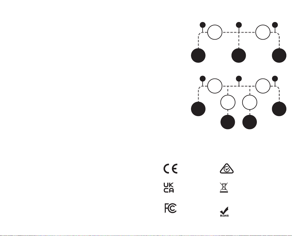
Low Pressure Sensor High Pressure SensorDeep Vacuum Sensor
Low Pressure Sensor High Pressure SensorDeep Vacuum Sensor
Deep Vacuum
Sensor Type: Thermistor
Port Type: SM382V: (3) 1/4” standard SAE male are ttings, or
SM482V: (1) 3/8” and (3) 1/4” standard SAE male are ttings
Range and Units:
50 to 9999 microns of mercury (English),
6.7 to 1330 Pascals (Metric),
0.067 to 13.30 mBar (Metric),
50 to 9999 mTorr (Metric),
0.050 to 9.999 Torr (Metric, equivalent to mmHg)
Best Resolution:
1 micron of mercury (below 2000 microns),
0.1 Pascal (below 250 Pascals),
0.001 mBar (below 2.500 mBar),
1 mTorr (below 2000 mTorr),
0.001 Torr (below 2.000 Torr)
Accuracy @ 25°C (77°F):
±(5% of reading + 5 microns of mercury), 50 to 2000 microns
±(5% of reading + 1.0 Pascal), 6.7 to 266.0 Pascal
±(5% of reading + 0.010 mBar), 0.067 to 2.660 mBar
±(5% of reading + 5 mTorr), 50 to 2000 mTorr
±(5% of reading + 0.005 Torr), 0.067 to 2.000 Torr
Manifold Diagrams
SM382V:
LOW
Port
LOW
Valve
REF
Port
HIGH
Valve
SM482V:
LOW
Port
LOW
Valve
VAC
Valve
VAC
Port
REF
Valve
REF
Port
HIGH
Valve
Certications and
HIGH
Port
HIGH
Port
Wireless Compatibility
Latest compatibility at www.fieldpiece.com
Job Link System Minimum Device Requirement:
BLE 4.0 devices running iOS 7.1 or AndroidTM Kitkat 4.4
Wireless Measurement Source Assignments:
Suction line temperature: Fieldpiece model JL3LC/PC (set to blue)
Liquid line temperature: Fieldpiece model JL3LC/PC (set to red)
Supply air psychrometer: Fieldpiece model JL3RH (set to blue)
Return air psychrometer: Fieldpiece model JL3RH (set to red)
Outdoor air psychrometer: Fieldpiece model JL3RH (set to red or blue)
Refrigerant weight scale: Fieldpiece models SRS3 or SR47
Vacuum: Fieldpiece model MG44
Module IDs
EN 300 328 Regulatory Compliance Mark
UK Conformity Assessed
IC: Industry Canada
Waste Electrical and
Electronic Equipment
Restriction of Hazardous
Substances Compliant
4746
Page 25

FCC Statement
This equipment has been tested and found to comply with the limits for a Class
B digital device, pursuant to Part 15 of the FCC Rules. These limits are designed
to provide reasonable protection against harmful interference in a residential
installation.
This equipment generates, uses and can radiate radio frequency energy and,
if not installed and used in accordance with the instructions, may cause harmful
interference to radio communications. However, there is no guarantee that
interference will not occur in a particular installation. If this equipment does cause
harmful interference to radio or television reception, which can be determined
by turning the equipment o and on, the user is encouraged to try to correct the
interference by one of the following measures:
. Reorient or relocate the receiving antenna.
. Increase the separation between the equipment and receiver.
. Connect the equipment into an outlet on a circuit dierent from that to which
the receiver is connected.
. Consult the dealer or an experienced radio/TV technician for help.
FCC Caution: To assure continued compliance, any changes or modications
not expressly approved by the party responsible for compliance could void the user’s
authority to operate this equipment. (Example - use only shielded interface cables
when connecting to computer or peripheral devices).
FCC Radiation Exposure Statement: This equipment complies with FCC RF
radiation exposure limits set forth for an uncontrolled environment. This equipment
should be installed and operated with a minimum distance of 0.5 centimeters
between the radiator and your body.
This transmitter must not be co-located or operating in conjunction with any
other antenna or transmitter.
The antennas used for this transmitter must be installed to provide a separation
distance of at least 0.5 cm from all persons and must not be co-located or operating
in conjunction with any other antenna or transmitter.
This device complies with Part 15 of the FCC Rules. Operation is subject to the
following two conditions:
(1) This device may not cause harmful interference, and (2) This device must
accept any interference received, including interference that may cause undesired
operation.
Industry Canada Statement
This device contains licence-exempt transmitter(s)/receiver(s) that comply with
Innovation, Science and Economic Development Canada’s licence-exempt RSS(s).
Operation is subject to the following two conditions:
(1) This device may not cause interference.
(2) This device must accept any interference, including interference that may
cause undesired operation of the device.
L’émetteur/récepteur exempt de licence contenu dans le présent appareil est
conforme aux CNR d’Innovation, Sciences et Développement économique Canada
applicables aux appareils radio exempts de licence. L’exploitation est autorisée aux
deux conditions suivantes :
1) L’appareil ne doit pas produire de brouillage;
2) L’appareil doit accepter tout brouillage radioélectrique subi, même si le
brouillage est susceptible d’en compromettre le fonctionnement.
IC Radiation Exposure Statement: This equipment complies with RSS-102
radiation exposure limit set forth for an uncontrolled environment. This equipment
should be installed and operated with minimum distance 0.5 cm between the
radiator and your body.
Cet équipement est conforme aux CNR-102 d’Industrie Canada. Cet équipement
doit êtreinstallé et utilisé avec une distance minimale de 0.5 centimètres entre
leradiateur et votrecorps. Cet émetteur ne doit pas être co-localisées ou opérant
en conjonction avec autreantenne ou émetteur. Les antennes utilisées pour cet
émetteur doivent être installés etfournir une distance de séparation d’au moins
0.5 centimètre de toute personne et doit pas être co-située ni fonctionner en
conjonction avec une autre antenne ou émetteur.
4948
Page 26

Limited Warranty
This product is warranted against defects in material or
workmanship for one year from date of purchase from an authorized
Fieldpiece dealer. Fieldpiece will replace or repair the defective unit, at
its option, subject to verication of the defect.
This warranty does not apply to defects resulting from abuse,
neglect, accident, unauthorized repair, alteration, or unreasonable use
of the machine.
Any implied warranties arising from the sale of a Fieldpiece product,
including but not limited to implied warranties of merchantability and
tness for a particular purpose, are limited to the above. Fieldpiece
shall not be liable for loss of use of the machine or other incidental or
consequential damages, expenses, or economic loss, or for any claim of
such damage, expenses, or economic loss.
State and country laws vary. The above limitations or exclusions
may not apply to you.
Obtaining Service
Visit www.eldpiece.com/rma for the latest information on how
to obtain service.
For customers outside the U.S., warranty for products should be
handled through local distributors.
Visit www.eldpiece-europe.com/store-locator.
Intentionally Blank
5150
Page 27

SM382V
SM482V
Job Link® System App
Link your Tools. Link your Jobs.
The Job Link® System works with all of our wireless tools—from
clamps to probes to digital manifolds, and integrates all of their
functionality seamlessly.
Download the app
to get started!
© Fieldpiece Instruments, Inc 2024; v08
 Loading...