

Page 1
O
F
F
NCV
VAC
VDC
AAC
Hz
SEL
HOLD
INRUSH
Fieldpiece
SEL
HOLD
HOLD
MAX
MIN
SYNC
MAX
MIN
HOLD
HOLD
MAX
MIN
SYNC
MAX
MIN
SC57
SC57
O
F
F
WIRELESS ENABLED
SEL
HOLD
HOLD
MAX
MIN
SYNC
MAX
MIN
O
F
F
M
FD
NCV
VAC
VDC
AAC
Hz
Hz
%
°C
SC56
SEL
HOLD
INRUSH
O
F
F
M
FD
NCV
VAC
VDC
AAC
Hz
Hz
%
°C
SC56
SEL
HOLD
INRUSH
O
F
F
SEL
HOLD
HOLD
MAX
MIN
SYNC
MAX
MIN
SC57
SC57
O
F
F
WIRELESS ENABLED
SEL
HOLD
HOLD
MAX
MIN
SYNC
MAX
MIN
SC57
SC57
O
F
F
SEL
HOLD
HOLD
MAX
MIN
SYNC
MAX
MIN
SEL
HOLD
INRUSH
HOLD
INRUSH
NCV
SEL
HOLD
INRUSH
O
F
F
NCV
VAC
VDC
AAC
Hz
SEL
HOLD
INRUSH
HOLD
INRUSH
SEL
HOLD
HOLD
MAX
MIN
SYNC
MAX
MIN
SC57
AUTO OFFTRUE RMS
CAT III
600V
TEMP
K-TYPE
30V
MAX
SC57
O
F
F
WIRELESS ENABLED
SEL
HOLD
HOLD
MAX
MIN
SYNC
SYNC
MAX
MIN
SC57
SC57
O
F
F
WIRELESS ENABLED
SEL
HOLD
HOLD
MAX
MIN
SYNC
SYNC
MAX
MIN
CAT.III
300V
400A
CLAMP
ACH4
AC Current
Clamp
1AAC / 1mVAC
400AAC MAX
!
ET2W
LO BATT
SEND
RECEIVE
ON
AC
DC
Wireless
Transmitter
SYNC
ET2W
LO BATT
SEND
RECEIVE
ON
AC
DC
Wireless
Transmitter
SYNC
ET2W
LO BATT
SEND
RECEIVE
ON
AC
DC
Wireless
Transmitter
SYNC
AUTO OFF
ARH4
SC57
AUTO OFFTRUE RMS
CAT III
600V
TEMP
K-TYPE
30V
MAX
SC57
O
F
F
WIRELESS ENABLED
SEL
HOLD
HOLD
MAX
MIN
SYNC
SYNC
MAX
MIN
HOLD
HOLD
MAX
MIN
DC
SEL
HOLD
INRUSH
O
F
F
NCV
VAC
VDC
AAC
Hz
SEL
HOLD
INRUSH
HOLD
Wireless
Swivel
Clamp
Meter
OPERATOR'S
MANUAL
Model SC57
01
Quick Start
Receive a Wireless Reading
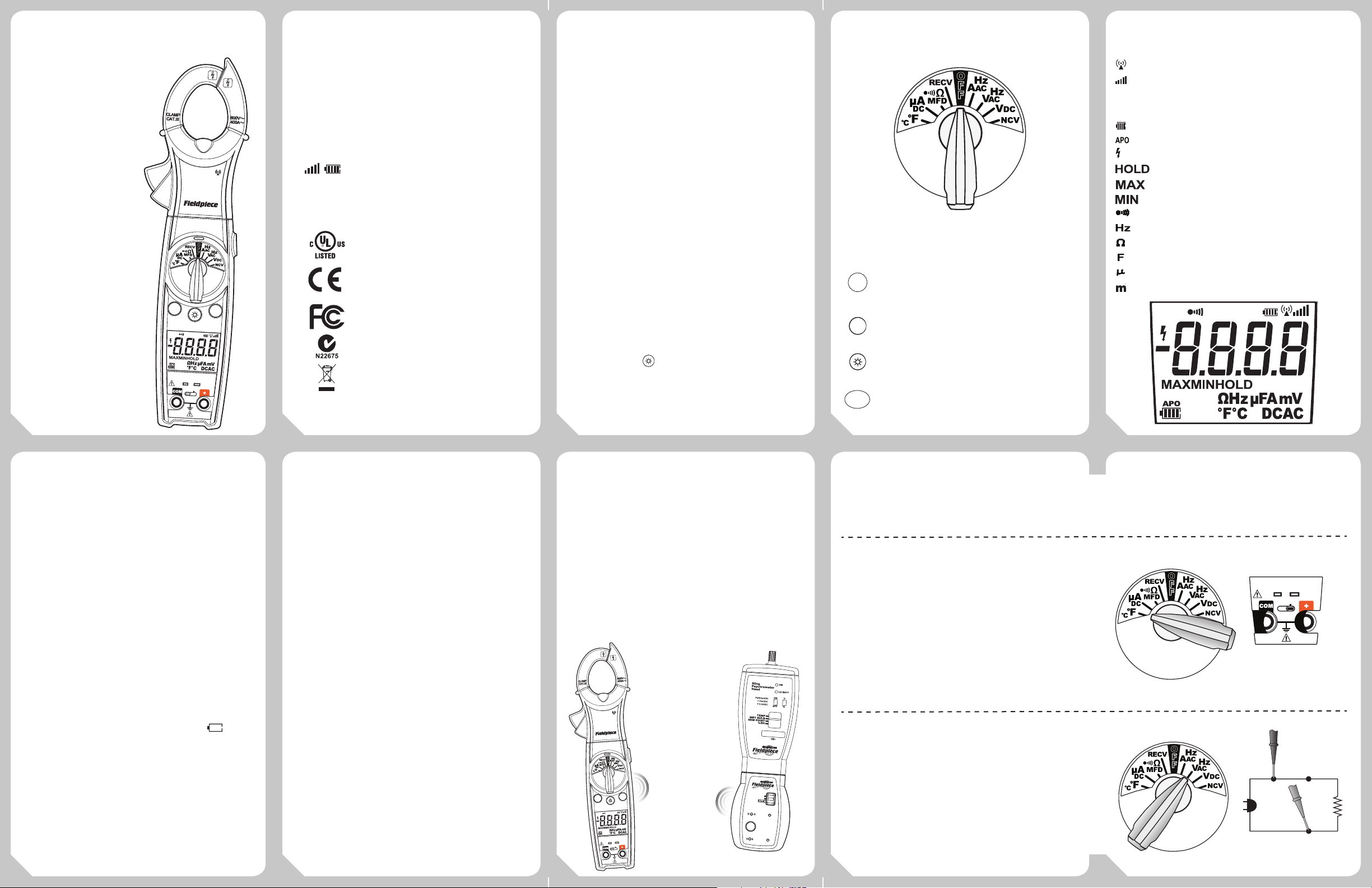
1. Select RECV on main dial of SC57.
2. Hold SYNC for one second.
3. Connect Fieldpiece accessory head to ET2W.
3. Turn ET2W to DC switch position.
4. Hold SYNC on ET2W for one second. When
connection is made the wireless reading and
icons will display on the SC57 screen.
Certifications
UL 61010-1, Second Edition
IEC/EN61010-1, EMC EN61326-1
IEC/EN61010-2-032
FCC
C-Tick (N22675)
WEEE
CATIII 600V, class II and pollution degree 2
indoor use comply with CE, RoHS compliant.
02
Description
As a proud owner of the first wireless
Fieldpiece clamp meter, SC57, you are well on
your way to eliminating tangled wires. SC57 will
give you the power to receive measurements
wirelessly from anywhere on the jobsite. For
instance, you can transmit indoor wet bulb
measurements for target superheat over the air
while you work at the condenser.
Your SC57 can receive measurements
wirelessly from any Fieldpiece accessory head
connected to a Fieldpiece wireless transmitter
like an ET2W or EH4W. Your SC57 comes with
one ET2W wireless transmitter.
In addition, your SC57 can transmit wirelessly
any measurement range on the dial to Fieldpiece
wireless receivers; like EH4W, HG3, LT17AW, or
another SC57.
SC57 is a swivel clamp meter designed for
the HVAC/R technician. The swivel on the
SC57 allows you to see the amperage reading,
regardless of wire orientation. The jaw light
and backlight
lighting condition. True RMS helps you take
more accurate voltage readings on variable
speed drives.
03
make it easier to use in any
Controls
O
F
F
Rotate dial to the function you want to use.
Hold for 1 second to connect with
SYNC
other Fieldpiece wireless products
Cycle through parameters or ranges
within a dial position
Press to illuminate backlight for 3 min
Press to freeze current, maximum or
HOLD
MAX
MIN
minimum reading
04
Display
Wireless Icon
Signal Strength Bars and Search
Pattern indicator when sending a
wireless measurement
Battery Life Indicator
Auto Power O Enabled
High Voltage Warning (+30V)
Data Hold Mode
Maximum Reading
Minimum Reading
Continuity Test
Frequency Test (hertz)
Resistance Test (ohms)
Capacitance Test (farads)
Micro Unit (10−6, one millionth)
Milli Unit (10−3, one thousandth)
05
Specifications
Wireless range: Up to 75 feet (23m) line of sight
Minimum wireless distance: 1 foot (30cm)
Wireless frequency: 910MHz to 920MHz (US), 868.1MHz to
868.5MHz (European)
Display: 10000 count display with backlight
Overrange: (OL) or (-OL) is displayed
Measurement rate: 2 times per second, nominal
Zero: Automatic
Operating environment: 32°F to 122°F (0°C to 50°C) at <70%
relative humidity
Storage temperature: -4°F to 140°F (-20°C to 60°C), 0 to 80% RH
(with battery removed)
Accuracy: Stated accuracy @ 73°F±9°F (23°C±5°C), <75%RH
Temperature coecient: 0.1 x (specied accuracy) per °C [0°C to
18°C (32°F to 64°F), 28°C to 50° C(82°F to 122°F)]
APO (Auto Power O): Approx. 30 minutes
Power: Single standard 9-volt battery, NEDA 1604, JIS 006P, IEC 6F22
Battery life: 100 hours typical alkaline
Low battery indication: Battery icon will be empty ( ). "batt"
displays along with a continuous beep when the battery voltage
drops below the operating level. Meter shuts o in 5 seconds.
Dimensions: 258.3mm(H) x 71.2mm(W) x 42.7mm(D)
Weight: Approx. 278g including battery
Altitude: 6562 feet (2000m)
Overload protection: 600VDC or 600VAC rms unless otherwise
stated in the individual test sections.
Test leads: Shall use UL listed test leads complied UL61010-031
rated CATIII 600V or above.
06
Functions
Wireless Receiver Mode
Use your SC57 to wirelessly receive a live
measurement you have set up at a diffeent
location on the jobsite. Like receiving an indoor
wet bulb temp. when your at the condensor.
Receiving Wireless Measurements
1. Select RECV switch position on SC57. Hold
SYNC button until meter beeps (>1 sec). Search
pattern initiates.
2. Connect and turn on any Fieldpiece accessory
head to the ET2W wireless transmitter.
3. Select DC switch position on ET2W for all acces-
sory heads except ACH4 (AC switch position).
4. Hold SYNC button on ET2W for one second.
5. The wireless measurement, signal strength,
and battery life of the ET2W will display in the
top-right corner of the SC57 screen.
Note: If the ET2W is not connected within 2 min,
the SC57 will beep and stop searching.
Wireless Transmitter Mode
Transmit electrical measurements wirelessly
from SC57 to Fieldpiece wireless receivers like
EH4W, LT17AW, HG3 or another SC57. Leave the
07
SC57 behind a closed fan door and send the amp
reading to the wireless receiver in your hand.
Sending Wireless Measurements
1. Select any switch position other than RECV.
2. Hold SYNC until meter beeps (>1 sec). Search
pattern will initiate.
3. Select RECV switch position on the Fieldpiece
wireless receiver. Hold SYNC button for one
second.
4. The measurement from the SC57 will be
displayed on the Fieldpiece wireless receiver.
ET2W w/ ARH4
transmitting wirelessly
to SC57
08
Wireless Auto-Connection
When powered on, SC57 will search and
connect to the last connected single-link
wireless partner device.
Temperature (°F/°C)
Plug any K-type thermocouple directly into the meter to measure
temperature. Cold junction is located inside the meter and allows for
extremely accurate measurements even in rapidly changing ambient
temperatures (going from rooftop to freezer). No adapter is required.
See Temp Calibration section for calibration instructions.
Range: -40°F to 2200°F, (-40°C to 1200°C) Resolution: 0.1°
Accuracy: ±(1°F) 32°F to 120°F, ±(1°C) 0°C to 49°C
±(1%+2°F) 120°F to 750°F, ±(1%+1°C) 49°C to 400°C
±(2%+6°F) -40°F to 32°F, ±(2%+3°C) -40°C to 0°C
±(2%+6°F) 750°F to 2200°F, ±(2%+3°C) 400°C to 1200°C
Sensor type: K-type thermocouple
Overload protection: 30 VDC or 30VAC rms
Voltage AC (VAC) (50Hz-400Hz)
Test power lines (120, 220, 480), test 24V going to controls, and
test for transformer failure.
Ranges: 0 to 600V Resolution: 0.1V
Accuracy: ±(1.0% + 5 dgts) 50-100Hz
±(6%+5 dgts) 100-400Hz
True RMS: Yes Crest factor: ≤ 3
Input impedance: 1MΩ
09
10
O
F
F
Unplug Leads and Slide
TEMP Switch to the Right
O
F
F
30V
MAX
TEMP
CAT III
600V
AUTO OFFTRUE RMS
K-TYPE
Page 2
MicroAmps DC (µADC)
SEL
HOLD
INRUSH
SEL
HOLD
INRUSH
SEL
HOLD
INRUSH
SEL
HOLD
INRUSH
A
B
C
!
!
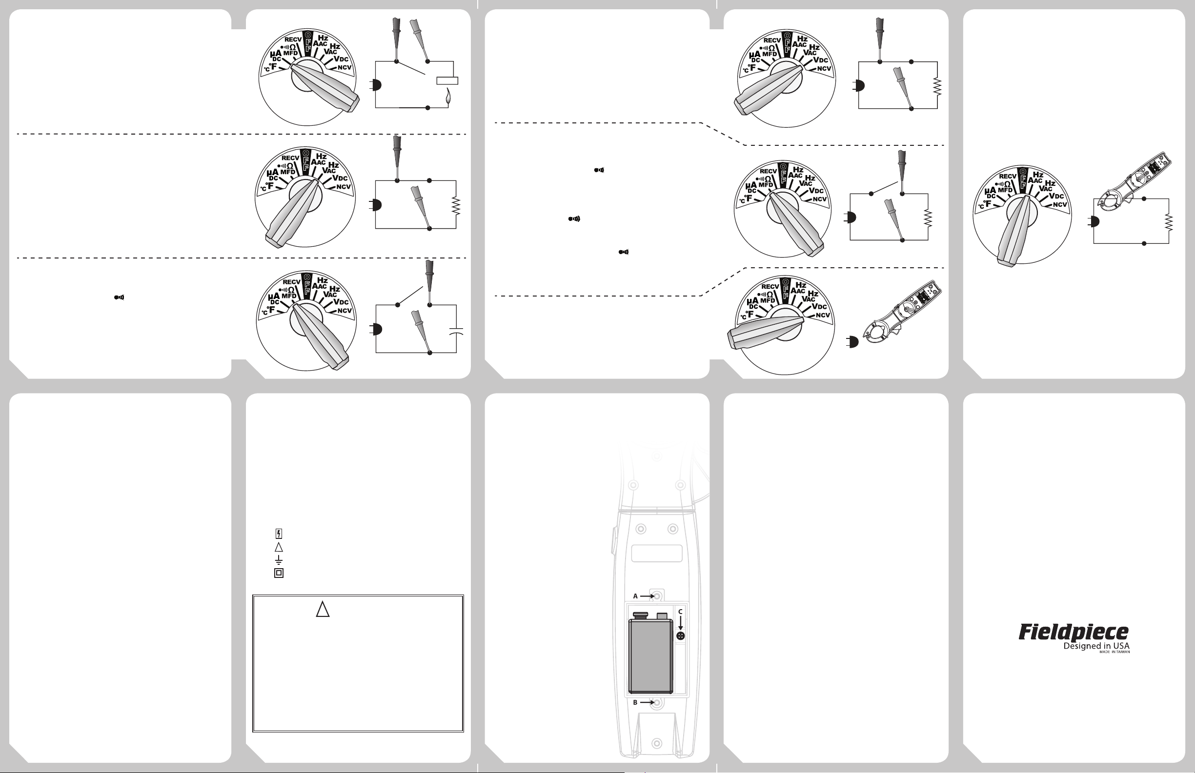
Microamps for ame rectier diode test on a heater control.
Connect leads between ame sensor probe and control module and
turn heating unit on to read µA measurement. When the ame is on,
there should be a measurable µADC signal, typically under 10µADC.
Compare measurement to manufacture’s specication to determine
if replacement is necessary.
Ranges: 1000µA Resolution: 0.1µA
Accuracy: ±(1.0% + 5 dgts) Voltage burden: 1V
Overload Protection: 600VDC or 600VAC rms
Frequency (Hz) Through Leads
Check variable frequency drives. Check incoming voltages to
ensure they are cycling at 60Hz or desired frequency. Select VAC/Hz
and press SEL button.
Ranges: 20 to 400Hz Resolution: 0.1Hz
Accuracy: ±(0.5% + 5 dgts)
Sensitivity: 5V rms on VAC range.
Capacitance (MFD)
Capacitors are one of the most failure prone components in
a HVAC/R system. Set to MFD/Ω/
capacitors. Discharge the capacitor and disconnect from power and
resistors between terminals before testing.
Ranges: 0 to 1000µF Resolution: 0.1µF
Accuracy: ±5% reading + 15 dgts
Overload Protection: 600VDC or 600VAC rms
11
to test motor start and run
12
O
F
F
Voltage DC (VDC)
Select VDC to measure DC voltage.
Ranges: 0 to 600V
Accuracy: ±(1.0% rdg + 5 dgts) on 600V range
Resolution: 0.1V Input impedance: 1MΩ
O
F
F
Resistance (Ω)
O
F
F
O
F
F
Used for “ohming out” a motor. 0.1Ω resolution is necessary to
test the resistance between the motor poles because the values are
typically very low. Select MFD/Ω/
Ranges: 0 to 1000Ω, 1000Ω to 9999Ω
Resolution: 0.1Ω Overload Protection: 600VDC/VAC rms
Accuracy: ±(1.5% + 5 dgts)
Continuity (
Use the continuity feature to test if a circuit is open or closed. Use
this feature to check fuses as well. A steady “beep” and green LED
indicate the circuit is good. Select MFD/Ω/
twice.
Range: 1000Ω Resolution: 0.1Ω Response time: 100ms
Audible beep: <30Ω Overload Protection: 600VDC/VACrms
and press SEL button once.
)
and press SEL button
O
F
F
O
F
F
SELRNG
Non Contact Voltage (NCV)
Use the non contact voltage (NCV) feature to test if a wire is hot or
not. Always test on a known live source before using. A red LED blinks
and beeping sound is emitted at >24VAC.
Discharge Cap First!
AC Voltage Detection Range: 24VAC to 600VAC (50-60Hz)
13
14
Amps AC (AAC) TrueRMS (50-60Hz)
Test any isolated power line. Select AAC/Hz dial position.
Ranges: 0 to 400AAC Resolution: 0.1A Crest factor: ≤ 3
Accuracy: ±(2.0% + 5 dgts) 50-60Hz
Jaw Opening: 1.2in (30 mm) Overload Protection: 400AAC
Frequency (Hz) Through Clamp
Measure frequency without using test leads, just use the clamp.
Turn dial to AAC/Hz and press SEL. Clamp Hz will be displayed.
Range: 20Hz to 400Hz Accuracy: ±(0.5% + 5)
Minimum current range: > 5AAC at 20 to 100Hz, >10AAC at 100
to 400Hz Resolution: 0.1Hz Overload Protection: 400AAC
O
F
F
SELRNG
BatteryReplacement
The battery must be replaced when the
battery icon is empty. "bAtt" will display with a
beeping sound. Meter will shut o in 5 seconds.
Disconnect and unplug leads, turn meter o
and remove battery cover.
15
Safety Information
• Never ground yourself when taking electrical
measurements. Do not touch exposed metal
pipes, outlets, xtures, etc., which might be
at ground potential, while taking measurements. Keep your body isolated from ground
by using dry clothing, rubber shoes, rubber
mats, or any approved insulating material.
• Disconnect the test leads before opening the
case. Inspect the test leads for damage to the
insulation or exposed wire. Replace if suspect.
Keep your ngers behind the nger guards
on the probes while taking measurements.
• When disconnecting from a circuit, disconnect
the “RED” lead rst, then the common “BLACK”
lead. Use one handed testing when possible.
Work with others.
• Turn o power to the circuit under test before
cutting, unsoldering, or breaking the circuit.
• Do not measure resistance (ohms) when circuit is powered. Isolate load by disconnecting
from circuit.
• Disconnect the meter from the circuit before
turning any inductor o, including motors,
transformers, and solenoids. High voltage
transients can damage the meter beyond
repair. Do not use during electrical storms.
• Do not apply more than rated voltages between input and ground.
• Isolate capacitors from system and discharge
them safely before testing.
All voltage tests: All voltage ranges will
withstand up to 600V. Do not apply more than
600VDC or AC rms.
Symbols used:
Caution, risk of electric shock
Caution, refer to manual.
Ground
Double insulation
WARNINGS
DISCONNECT AND UNPLUG TEST LEADS before opening case.
TEST NCV FUNCTION ON KNOWN LIVE WIRE before using.
DO NOT APPLY VOLTAGE greater than 30VAC or 60VDC to the
thermocouple or the jacks when the rotary dial is on °F. (Use
only k-type thermocouples)
REMOVE THE THERMOCOUPLE when taking voltage measurements.
DISCONNECT TEST LEADS when measuring temperature.
DO NOT APPLY VOLTAGE TO THE JACKS when the rotary dial is on
microamps. Even low voltages can cause a current overload and
potentially harm the meter.
Temp. Calibration
For accuracies of ±1°F,
calibrate to a known
temperature. A glass
of stabilized ice water
is very close to 32°F
(0°C) and is usually very
convenient but any
known temperature can
be used.
1. Select the °F/ °C range.
2. Plug thermocouple to be
calibrated into the K-type jack.
3. Unscrew A and B and remove
the battery cover.
4. Stabilize a large cup of ice
water. Stir the ice with the
water until temperature stays
at 32°F (0°C).
5. Immerse the thermocouple
probe and let it stabilize. Keep
stirring to prevent micro-
environments.
6. Use a small screwdriver to
adjust calibration pot C to the
right of the battery as close to
32°F as you would like.
Maintenance
Clean the exterior with a dry cloth. Do not
use liquid.
Limited Warranty
This meter is warranted against defects in
material or workmanship for one year from
date of purchase. Fieldpiece will replace or
repair the defective unit, at its option, subject
to verication of the defect.
This warranty does not apply to defects
resulting from abuse, neglect, accident,
unauthorized repair, alteration, or unreasonable
use of the instrument.
Any implied warranties arising from the sale of
a Fieldpiece product, including but not limited
to implied warranties of merchantability and
tness for a particular purpose, are limited to
the above. Fieldpiece shall not be liable for loss
of use of the instrument or other incidental or
consequential damages, expenses, or economic
loss, or for any claim of such damage, expenses,
or economic loss.
State laws vary. The above limitations or
exclusions may not apply to you.
Obtaining Service
Call Fieldpiece Instruments for one-pricefix-all out-of-warranty service pricing. Send
check or money order for the amount quoted.
Send the meter freight prepaid to Fieldpiece
Instruments. Send proof of date and location
of purchase for in-warranty service. The meter
will be repaired or replaced, at the option
of Fieldpiece, and returned via least cost
transportation.
www.fieldpiece.com
© Fieldpiece Instruments, Inc 2012; v07
16
17
18
19
20
 Loading...