

GeoSnap Pro
User Manual

© Field of View 2018 GeoSnap Pro User Manual
2 2 2
Date
Revision
3/17/14
Manual created
4/1/14
Added VN-200 INS state error code table
4/3/14
Added GPS antenna installation instructions
5/26/14
Added Garmin trigger mode description
9/26/14
Updated voltage range
9/26/14
Added instructions for using a new microSD card
2/19/15
Updated CONFIG file section to include new image file names
6/8/15
Adjusted GeoSnap Pro naming convention
12/14/15
Added Troubleshooting section
2/11/16
Updated to match 2.3.x firmware
3/28/16
Added File synchronization procedure
5/23/16
Updated to match 2.4.x firmware
6/29/16
Updated
7/18/17
Added camera cycle time section
11/30/17
Clarified antenna offset
8/17/18
Updated and reworked entire manual

© Field of View 2018 GeoSnap Pro User Manual
3 3
CONTENTS
OVERVIEW ............................................................................................................................4
GeoSnap Pro Components ..................................................................................................4
Control Unit................................................................................................................................................... 4
Hotshoe Module ........................................................................................................................................... 4
Accessories .................................................................................................................................................... 4
GETTING STARTED................................................................................................................5
Installing the GeoSnap Pro on a DSLR-style Camera .............................................................5
Mounting the GPS Antenna ......................................................................................................................... 6
Pigtail Trigger Cable ...................................................................................................................................... 6
Using the GeoSnap Pro .......................................................................................................7
GeoSnap Files................................................................................................................................................ 7
Synchronizing Image Names ........................................................................................................................ 9
Configuring for Mapping Flights .................................................................................................................. 9
Powering On the GeoSnap ........................................................................................................................... 9
LED Codes .................................................................................................................................................... 10
CONFIGURATION FILE ........................................................................................................11
AUXILIARY I/O CONNECTIONS ...........................................................................................24
External Trigger Input ....................................................................................................... 24
UPDATING FIRMWARE .......................................................................................................25
OPERATIONS CHECKLIST ....................................................................................................26
CAMERA SETTINGS .............................................................................................................27
Required and Recommended Settings ............................................................................... 27
Image numbering ............................................................................................................. 28
Camera cycle time considerations ..................................................................................... 28
TROUBLESHOOTING ...........................................................................................................30
GPS signal quality test ...................................................................................................... 30
Basic test ..................................................................................................................................................... 30
Identification test ....................................................................................................................................... 31
INS_stat code lookup tables.............................................................................................. 32
SPECIFICATIONS .................................................................................................................33
Physical specifications ...................................................................................................... 33
Power specifications......................................................................................................... 34
MicroSD card specifications .............................................................................................. 34
© Field of View 2018 GeoSnap Pro User Manual
4 4 4
OVERVIEW
GeoSnap Pro Components
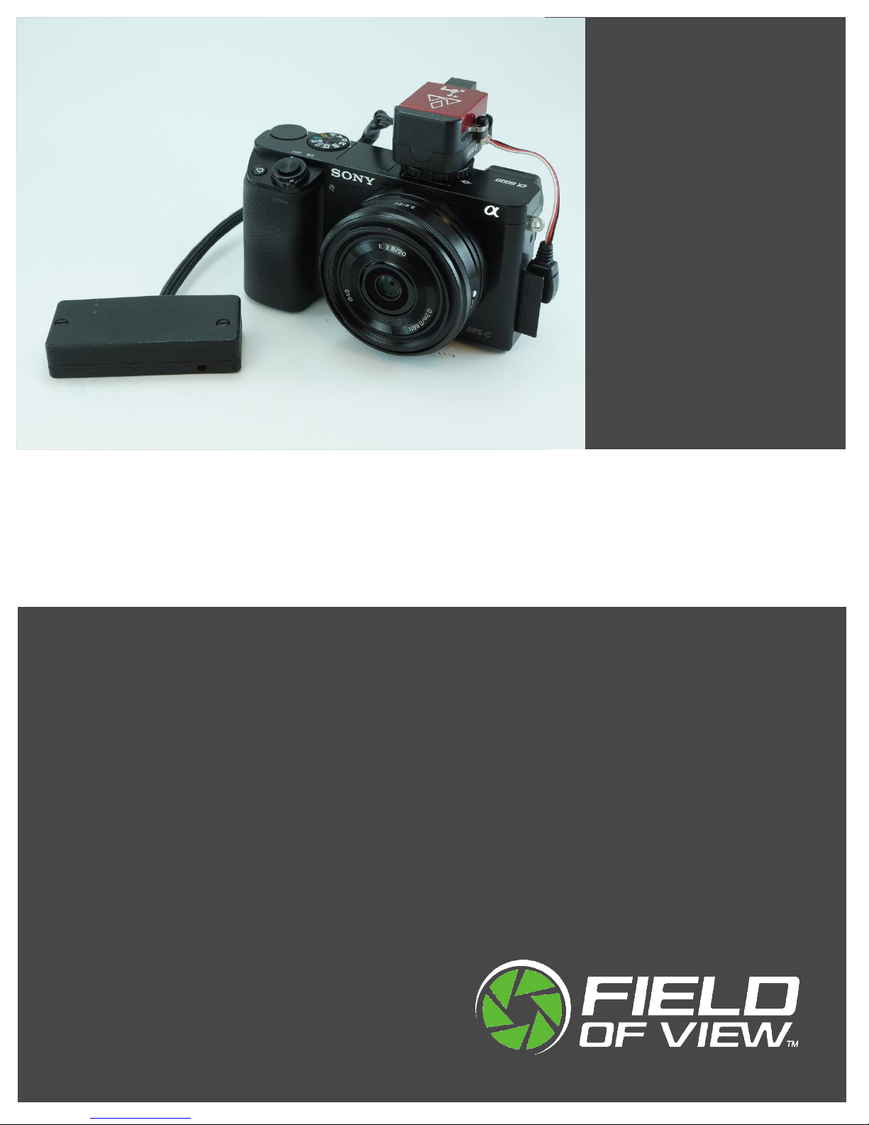
The Field of View GeoSnap Pro was developed to streamline DSLR-style camera payload
integration, facilitate intelligent triggering, and produce a valuable log of position/attitude
conditions at the moment of image capture.
CONTROL UNIT
HOTSHOE MODULE
ACCESSORIES
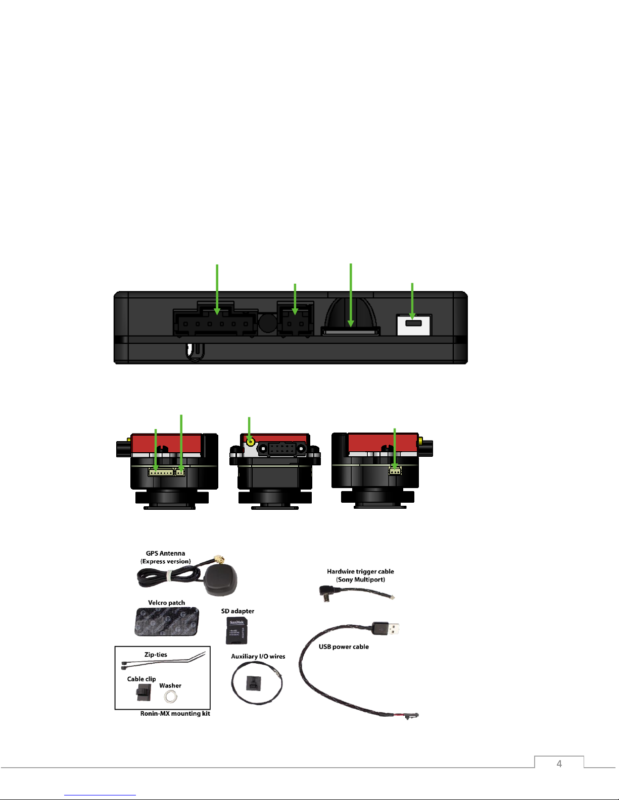
Power input
MicroSD card slot
Onboard button
Auxiliary I/O port
Wired trigger port
Control unit port
IR LED port
GPS antenna port

© Field of View 2018 GeoSnap Pro User Manual
5 5
GETTING STARTED
Installing the GeoSnap Pro on a DSLR-style Camera
Slide the hotshoe module onto
the hotshoe of the camera and
twist the lock ring clockwise
to tighten down the lock.
Pull back on the GPS antenna
strain relief and swivel the
GPS antenna cable into place.
Plug the GPS antenna’s MMCX
connector into the antenna port
on the VN-200 (press until it
clicks into place).
Plug the trigger cable into
the hotshoe module and the
camera trigger port.
© Field of View 2018 GeoSnap Pro User Manual
6 6
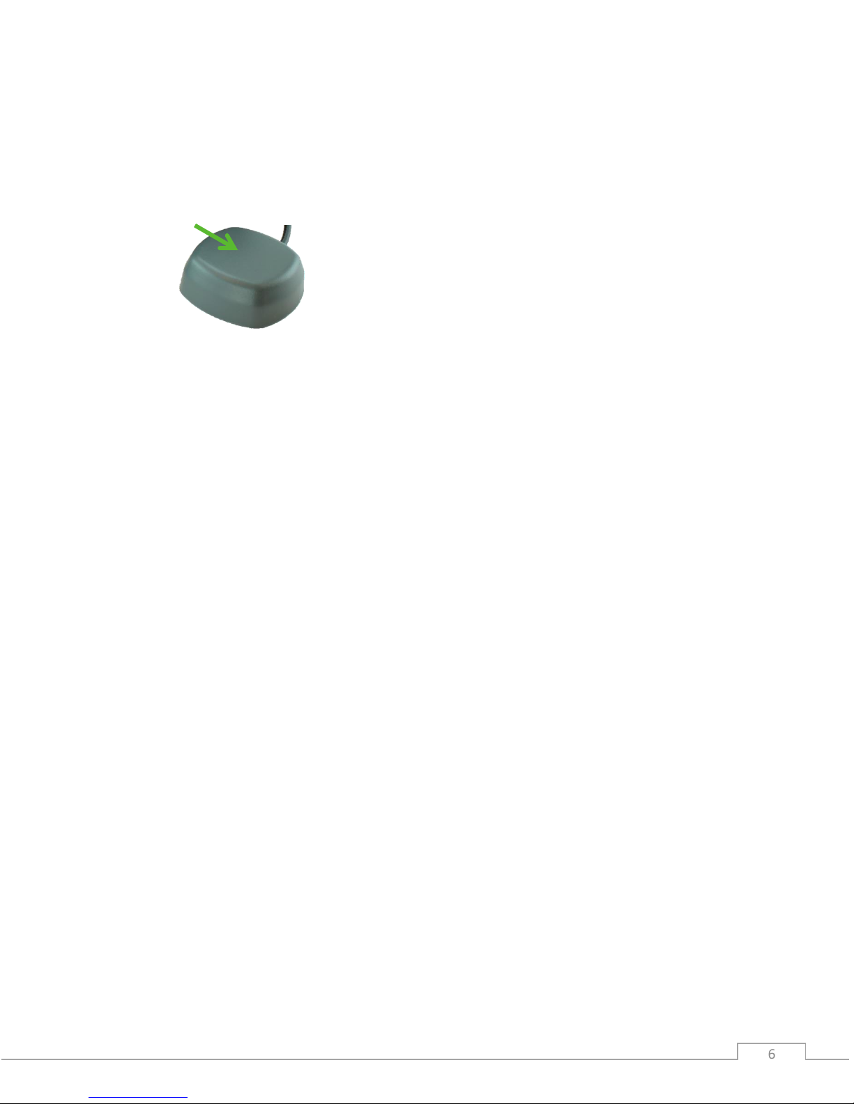
MOUNTING THE GPS ANTENNA
Make sure you mount the GPS antenna with the top facing up and with a clear view of the sky.
Also make sure that you do not mount the antenna near transmitters on the aircraft that could
cause interference and degrade the performance of the GPS.
Ground plane (optional)
To improve your GPS accuracy, it is recommended that you place a 10 cm diameter round or 10
cm x 10 cm square ground plane under the GPS antenna. This could be as simple as placing
some aluminum tape (that you can buy from a hardware store) around a piece of wood or
cardboard, sticking the antenna to the center of the plate, and attaching that whole assembly to
the top of your aircraft.
PIGTAIL TRIGGER CABLE
If you are not using a camera with a Sony multiport trigger connection, you will have been
provided with a 3-wire (green, white, black) pigtail trigger cable. When the GeoSnap system
sends a trigger command to the camera, it simply shorts the focus (white) and shutter release
(green) lines to ground (black). To make a trigger cable for your camera with this pigtail it is
recommended that you follow these steps:
1. Purchase a stock wired remote for your particular camera model.
2. Cut the stock remote cable 1-5” from the connector depending on the location of the
wired remote port relative to the GeoSnap hotshoe module.
3. Strip the ends of the stock remote cable wires.
4. Identify which cables in the stock cable relate to Ground, Focus, and Shutter Release.
5. Connect the wires to the provided pigtail trigger cable as follows: Ground -> Black, Focus
-> White, and Shutter Release -> Green.
6. Plug the cable into the camera and the GeoSnap hotshoe module as shown in steps 6
and 7 of the GeoSnap installation procedure above.
TOP

© Field of View 2018 GeoSnap Pro User Manual
7 7
Using the GeoSnap Pro
GEOSNAP FILES
There are various text files stored and/or logged on the microSD card. These files, and their
purposes, are described in this section.
Configuration File (CONFIG.txt)
The CONFIG file is where you can adjust all of the settings of the GeoSnap. Each time the
GeoSnap is powered, it searches for the configuration file and reads the settings. If this file is not
present, the GeoSnap creates a new configuration file with default options. For full descriptions
of all the settings in the CONFIG file, see the Configuration File section of this manual.
Image Log File (001-IMG.txt)
The IMG log file is a log of the image name and position/attitude of the camera at the moment
of image capture. Information is logged as plain, ASCII text in space-separated columns; each
column is 14 characters wide.
Image Log File Columns
Label
Units
Description
image
name
Image name/counter
gpsdate
YYYY-MM-DD
Date as reported by the VN-200
gpstime
HH:MM:SS.SSS
Time as reported by the VN-200
lat(deg)
degrees
Latitude as reported by the VN-200
lon(deg)
degrees
Longitude as reported by the VN-200
hght(wgs84-m)
meters
Height above WGS84 ellipsoid
roll(deg)
degrees
Roll as reported by the VN-200 (positive roll is a roll to the right)
pitch(deg)
degrees
Pitch as reported by the VN-200 (positive pitch is a pitch up)
yaw(deg)
degrees
Yaw as reported by the VN-200
gstime(ms)
milliseconds
GeoSnap time since power on
AttUncrt(deg)
degrees
Attitude uncertainty of the VN-200
PosUncrt(m)
meters
Position uncertainty of the VN-200

© Field of View 2018 GeoSnap Pro User Manual
8 8
Pix4D Log File (001-P4D.txt)
The Pix4D log file is a Pix4D compatible log of the image name and position of the camera at the
moment of image capture. Information is logged as plain, ASCII text in comma-separated
columns.
Pix4D Log File Columns
Label
Units
Description
imagename
name
Image name/counter
latitude
degrees
Latitude as reported by the VN-200
longitude
degrees
Longitude as reported by the VN-200
altitude
meters
Height above WGS84 ellipsoid
Flight Log File (001-FLT.txt)
The FLT log file is a 25Hz log of the position/attitude of the camera throughout the flight. If the
log reaches 3 million lines a new FLT file is created with a letter appended to it using the
following convention: 001-FLT.txt, 001- FLTA.txt, 001-FLTB.txt, etc. Information is logged as plain,
ASCII text in space-separated columns; each column is 14 characters wide.
Flight Log File Columns
Label
Units
Description
gpsdate
YYYY-MM-DD
Date as reported by the VN-200
gpstime
HH:MM:SS.SSS
Time as reported by the VN-200
lat(deg)
degrees
Latitude as reported by the VN-200
lon(deg)
degrees
Longitude as reported by the VN-200
hght(wgs84-m)
meters
Height above WGS84 ellipsoid
roll(deg)
degrees
Roll as reported by the VN-200 (positive roll is a roll to the right)
pitch(deg)
degrees
Pitch as reported by the VN-200 (positive pitch is a pitch up)
yaw(deg)
degrees
Yaw as reported by the VN-200
gstime(ms)
milliseconds
GeoSnap time since power on
AttUncrt(deg)
degrees
Attitude uncertainty of the VN-200
PosUncrt(m)
meters
Position uncertainty of the VN-200
INS_stat
Status of the INS as reported by VN-200

© Field of View 2018 GeoSnap Pro User Manual
9 9
Imagenum File (IMAGENUM.txt)
This file keeps track of the numbering of the images in the IMG and Pix4D log files. To restart the
numbering at 1, simply delete the IMAGENUM file from the GeoSnap microSD card.
SYNCHRONIZING IMAGE NAMES
The GeoSnap does not get the actual image names from the camera but uses a sequential
numbering scheme in the specified image name format. Because of this, it is important that the
camera and the GeoSnap be set up so that they both start image numbering at 1 and remain
synchronized through use.
It is recommended to set the camera’s file numbering setting to Reset (for more information on
this, see the Camera Settings section of this manual). Then, before you start a new mission, clear
all images off the camera’s SD card and delete the IMAGENUM.txt file off the GeoSnap card. This
will reset both systems to start image numbering at 1.
CONFIGURING FOR MAPPING FLIGHTS
For mapping missions, we recommend setting up the GeoSnap to trigger the camera using the
distance interval option. The appropriate distance interval can be obtained from your flight
planning software, or from Field of View’s flight planning calculator, available at
fieldofviewllc.com/downloads. To configure the GeoSnap for distance interval triggering:
1. Insert the GeoSnap microSD card into a computer
2. Open the CONFIG.txt file using a text editor (e.g. Notepad)
3. Edit the following CONFIG file options to the specified settings, then save and replace
microSD card in the GeoSnap
@2: File_name = camera dependent (select the correct option for your camera)
@3: Trigger mode = 2
@5: Trigger_dist_m = your desired trigger distance interval in meters
@20: Antenna_offset_m = installation dependent (see the Configuration File
section of this manual for more information on how to properly use this option)
POWERING ON THE GEOSNAP
To power on the GeoSnap, simply plug in the provided USB power cable, or the power pigtail
cable connected to an appropriate power source (see the Specifications section of this manual
for power specifications). Before powering down the system, press and hold the onboard button
for approximately 3 seconds until all LED shine solid. This ends logging, making it safe to remove
power from the system.
Dynamic Motion
The VN-200 requires dynamic motion to reach full heading accuracy. Because of this, if you are
using the GeoSnap Pro on a multirotor, we highly recommend performing a few S-turns in
manual flight mode at the start of the flight before sending it on its autonomous mission.
© Field of View 2018 GeoSnap Pro User Manual
10 10
LED CODES
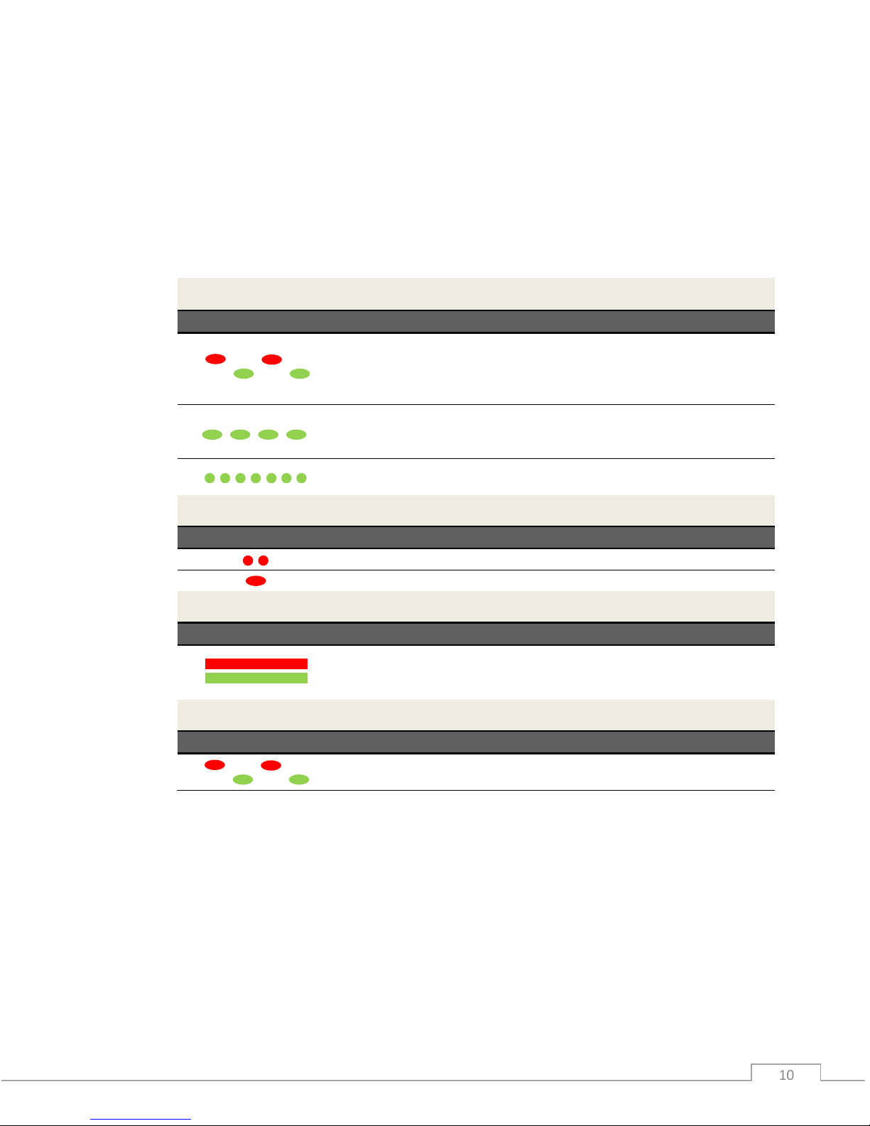
The meanings of the LEDs on the GeoSnap board are explained in this section.
• Blue LED – This LED indicates when the board is powered. When power is sent to the
board, this LED shines solid.
• Red LED & Green LED – These LEDs indicate the status of the GeoSnap, including startup
status, GPS status, triggering, and camera capture indications.
Startup Sequence
LED Code
Meaning
Board is checking for access to the microSD card and writing a default
CONFIG file to the card if a CONFIG file does not already exist. *Note: this
is also the LED code for an SD card error (see below) so if this pattern
persists, check the SD card.
No GPS lock but system is ready to start operating. If the GeoSnap is
configured for fast as possible or time triggering, the first trigger
command will be sent at this point
GPS lock. If the GeoSnap is configured for distance triggering, the first
trigger command will be sent at this point.
Capturing Images
LED Code
Meaning
Trigger command sent.
Capture confirmation received from camera.
Shutdown
LED Code
Meaning
All data logging has stopped and it is safe to power down the system. This
occurs after pressing and holding the trigger button for approximately 3
seconds.
Errors
LED Code
Meaning
MicroSD card error. Occurs when there is no card, the card is not seated
properly, the card is full, or if the log file number exceeds 999.
© Field of View 2018 GeoSnap Pro User Manual
11 11
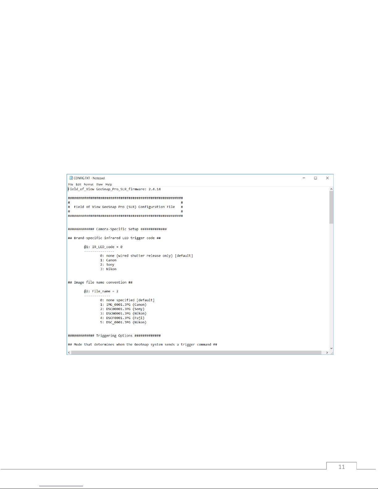
CONFIGURATION FILE
The CONFIG.txt file on the GeoSnap’s microSD card is where you can adjust all of the settings of
the GeoSnap. Each time the GeoSnap is powered, it searches for the configuration file and reads
the settings. If this file is not present, the GeoSnap creates a new configuration file with default
options.
The file consists of human-readable ASCII text and can be edited using many types of text
editors. On Windows, either Notepad or Wordpad may be used. On OSX, TextEdit may be used.
On GNU/Linux or Unix, EMACS, Vim, Nano, Pico, or other graphical equivalents may be used.
Note: word processing software such as Microsoft Word should not be used to edit the
configuration file.
The sections below describe in detail the various settings and how their options/values affect
the behavior of the GeoSnap.

© Field of View 2018 GeoSnap Pro User Manual
12 12
Brand-specific infrared LED trigger code
Default String:
@1:IR_LED_code = 0
Values:
0: none (wired shutter release only) [default]
1: Canon
2: Sony
3: Nikon
Description:
If you are using a wired trigger cable to trigger the camera, you can keep this value at the
default option ‘0’. This option was used to control the IR code that is output by the GeoSnap
to trigger the camera via an IR trigger cable (this cable is no longer provided standard with
the GeoSnap due to wired triggering being more reliable).
Image file name convention
Default String:
@2:File_name = 0
Values:
0: none specified [default]
1: IMG_0001.JPG (Canon)
2: DSC00001.JPG (Sony)
3: DSCN0001.JPG (Nikon)
4: DSCF0001.JPG (Fuji)
5: DSC_0001.JPG (Nikon)
Description:
This option allows you to specify what will be entered into the “image” column in the image
log file and Pix4D log file. If option ‘0’ is selected, the “image” entry in the log file will be
filled with a counter that can be converted to image names in post-processing using
Geotility. If an actual image name is selected the “image” entry in the image log file will be
filled with consecutively numbered image names. For example, if option ‘1’ is selected, the
entries in the “image” column will take the form of IMG_0001.JPG, IMG_0002.JPG, etc.

© Field of View 2018 GeoSnap Pro User Manual
13 13
Mode that determines when the GeoSnap system sends a trigger
command
Default String:
@3:Trigger_mode = 0
Values:
0: onboard button only [default]
1: time
2: distance
3: fast-as-possible
4: low->high input signal
5: high->low input signal
6: low->high and high->low input signal
7: Garmin portable aviation GPS waypoint arrival/time interval
Description:
Set this option to specify the camera triggering mode of the GeoSnap.
• Onboard button only: a trigger command is sent when the GeoSnap’s onboard
button is pushed.
• Time: trigger commands are sent at a uniform time interval that is specified in the
time interval option.
• Distance: trigger commands are sent at a uniform distance interval (calculated from
the latitude and longitude obtained from the GPS) that is specified in the distance
interval option.
• Fast-as-possible: a trigger command is sent immediately after the GeoSnap receives
capture verification from the camera from the prior trigger command.
• Input signal modes (options 4, 5, and 6): a trigger command is sent every time the
GeoSnap receives an external input signal as listed in the option. For example, if
‘low->high input signal’ is selected, the GeoSnap will send a trigger command to the
camera every time the external input signal transitions from low to high voltage (for
more information on using an external input signal, see the External Connections
section of this manual).
• Garmin portable aviation GPS waypoint arrival/time interval (legacy feature): a
trigger command is sent every time a waypoint that is set in a Garmin portable
aviation GPS is reached. It will also send a trigger command at the specified time
interval when the switch on the handheld remote (part of the Garmin portable
aviation GPS GeoSnap solution) is in the always on position.

© Field of View 2018 GeoSnap Pro User Manual
14 14
For mode 1 or 7 above, specify a time interval in seconds
Default String:
@4:Trigger_time_sec = 2.0
Values:
0.1 - 64800 seconds (in tenth of a second increments)
Description:
This option sets the amount of time (in seconds) between trigger commands sent by the
GeoSnap when it is set to time mode triggering (or when the handheld remote switch is set
to the always on position in a Garmin setup). This is configurable in tenth of a second
increments. The trigger mode must be set to 1 or 7 in order for this option to have any
effect on system operation.
For mode 2 above, specify a distance interval in meters
Default String:
@5:Trigger_dist_m = 50
Values:
1 - 10000 meters (in meter increments)
Description:
This option sets the distance (in meters) between trigger commands sent by the GeoSnap
when it is set to distance mode triggering. This is configurable in meter increments. Any
decimals entered will be truncated. The trigger mode must be set to 2 in order for this
option to have any effect on system operation.
Length of time the GeoSnap system waits for capture verification from
the camera before resending the trigger command
Default String:
@6:Resend_trig_time_ms = 500
Values:
0 - 60000 milliseconds
Description:
This option allows you to set the amount of time the GeoSnap waits for capture verification
before resending the trigger command. This option gives you control over your mission
quality control by allowing you to specify the amount of time to wait and see if the camera
took a picture before identifying a missed trigger and attempting to salvage the trigger
point.

© Field of View 2018 GeoSnap Pro User Manual
15 15
Use external input signal or onboard button to control time mode, fast-aspossible mode, and/or distance mode
Default String:
@7:Control_mode= 0
Values:
0: feature disabled [default]
1: high input signal enables time mode, fast-as-possible mode, or
distance mode
2: low input signal enables time mode, fast-as-possible mode, or
distance mode
3: onboard button starts time mode or fast-as-possible mode
4: onboard button toggles (starts/stops) time mode or fast-as
possible mode
Description:
This option allows you to use an external input signal to enable time mode, fast-as-possible
mode, or distance mode; or to use the GeoSnap onboard button to start and/or stop time
mode or fast-as-possible mode. If this feature is disabled and the GeoSnap is in time, or fastas-possible mode, it will start sending trigger commands as soon as it is powered. If this
feature is disabled and the GeoSnap is in distance mode, it will start sending trigger
commands as soon as a GPS lock is acquired.
If one of the input signal options (1 or 2) is selected, time, distance, or fast-as-possible
triggering will only be allowed when the external input signal is held high or held low
(depending on the option selected). This is useful if images are only desired during a certain
portion of the flight.
If option 3 is selected, time or fast-as-possible triggering won’t start until the button is
pressed, and subsequent button presses will be ignored. If option 4 is selected, time or fastas-possible triggering won’t start until the button is pressed and subsequent button presses
will stop and start the triggering.
Activate time mode or fast-as-possible mode when the GeoSnap system
detects an initial image capture
Default String:
@8:Initial_image_activation = 0
Values:
0: feature disabled [default]
1: feature enabled

© Field of View 2018 GeoSnap Pro User Manual
16 16
Description:
This option configures whether to start time or fast-as-possible triggering after an initial
camera image capture has been detected by the GeoSnap. This initial image capture could
be initiated using the shoulder button on the camera or with an external signal input.
Send trigger command at least every X minutes to prevent camera liveview timeout
Default String:
@9:Elapsed_time_min = 0
Values:
0 – 600000 min
Description:
This option is designed for use with a manned aircraft setup with Canon Live-View. The
Canon camera kicks out of Live view mode after a period of inactivity. This option allows you
to have the GeoSnap keep track of length of inactivity (i.e. no camera triggers) and send a
trigger command at the specified number of minutes if no activity has happened. For
example, if you set the value to 10 and there were no images taken after 10 minutes, the
GeoSnap would command a trigger at that point. To disable this feature, simply set the
value to 0.
Only allow time mode, distance mode, or fast-as-possible mode within
specified pitch/roll angles
Default String:
@10:Enable_PR_limit = 0
Values:
0: feature disabled [default]
1: feature enabled
Description:
This option allows you to constrain the GeoSnap so that it pauses image triggering when the
aircraft pitches or rolls beyond a specified limit. For example, when the roll limit is set to 45
degrees, the GeoSnap will not send a trigger command at any time that the VN-200 is
outputting roll values greater than or equal to 45 degrees or less than or equal to -45
degrees. A trigger not sent due to aircraft attitude is sent as soon as the attitude falls within
the set limits.

© Field of View 2018 GeoSnap Pro User Manual
17 17
Roll limit
Default String:
@11:Roll_limit_deg = 45
Values:
0 – 180 degrees (to the nearest degree)
Description:
This option configures the roll limit associated with Pitch/Roll limit option. The Pitch/Roll
limit option must be enabled for this to take effect. This is configurable in one degree
intervals only. Any decimals entered will be truncated.
Pitch limit
Default String:
@12:Pitch_limit_deg = 45
Values:
0 – 90 degrees (to the nearest degree)
Description:
This option configures the pitch limit associated with Pitch/Roll limit option. The Pitch/Roll
limit option must be enabled for this to take effect. This is configurable in one degree
intervals only. Any decimals entered will be truncated.
Only allow time mode, distance mode, or fast-as-possible mode above a
specified WGS84 altitude
Default String:
@13:Enable_altitude_limit = 0
Values:
0: feature disabled [default]
1: feature enabled
Description:
This option allows you to constrain the GeoSnap so that it pauses image triggering when the
aircraft is below a certain WGS-84 altitude. This is useful to prevent image capture while the
aircraft is on the ground.

© Field of View 2018 GeoSnap Pro User Manual
18 18
WGS84 altitude limit
Default String:
@14:Minimum_altitude_m = 50
Values:
1 - 65536 meters (to the nearest meter)
Description:
This option configures the altitude limit associated with the altitude limit option. The
altitude limit option must be enabled for this to take effect. This is configurable in one
meter intervals only. Any decimals entered will be truncated.
Associate and log position/attitude data at the moment the trigger
command is sent, not when capture verification is received
Default String:
@15:Blind_logging = 0
Options:
0: feature disabled [default]
1: feature enabled
Description:
This option allows you to ignore capture verification completely and associate and log
position/attitude data at the time that the trigger command is sent. Since capture
verification is ignored when blind logging is enabled, if you are in fast-as-possible mode the
GeoSnap will send a trigger command at the interval specified in the Resend_trig_time_ms
option (option @6).
Associate position/attitude data with the image ‘x’ milliseconds after
capture verification is received
Default String:
@16:Association_delay_ms = 0
Description:
This option allows you to add a delay between when the GeoSnap received capture
verification and when the position/attitude association is performed and written to the
image log file.

© Field of View 2018 GeoSnap Pro User Manual
19 19
Select which log files to generate
Default String:
@17:Data_logging = 0
Options:
0: generate image log, pix4d log, and flight data log [default]
1: generate image log and flight data log only
2: generate image log and pix4d log only
3: generate image log only
Description:
This option configures whether or not to create and populate the IMG, P4D, and/or FLT log
files on the GeoSnap’s microSD card.
VN-200 orientation relative to the camera
Default String:
@18:VN_orientation = 0
Options:
0: default orientation [default]
1: custom orientation
Description:
Use this option to select the orientation of the VN-200 relative to the camera. The default
orientation (0,0,-1,0,1,0,1,0,0) is appropriate for the standard GeoSnap installation on the
hotshoe of the camera. In this orientation the X-axis of the VN-200 and the camera lens are
pointing in the same direction, with the Z-axis of the VN-200 pointing down out of the
bottom of the camera. If the VN-200 is mounted in a different orientation relative to the
camera, select option 1 and specify the appropriate reference frame rotation in the
following option.
For option 1 above, specify the reference frame rotation for the VN-200
Default String:
@19:Reference_frame = 0,0,-1,0,1,0,1,0,0
Values:
C00,C01,C02,C10,C11,C12,C20,C21,C22
is translated to

© Field of View 2018 GeoSnap Pro User Manual
20 20
Description:
This input defines the transformation matrix required to align the body frame of the VN-200
to the camera frame of reference. This allows for the VN-200 to be placed in any arbitrary
orientation with respect to the camera. The default string is the appropriate string for the
standard mounting configuration of the VN-200 on the GeoSnap hotshoe module.
The variables {X, Y, Z}B are a measured parameter in the body reference frame with respect
to the VN-200. The variables {X, Y, Z}C are a measured parameter in the camera’s frame of
reference.
GeoSnap performs an internal transformation to assign the standard aircraft coordinate
system to the camera so that the Z-axis is pointing out of the lens, the X-axis is off of the top
of the camera, and the Y-axis is off of the right of the camera. This can be seen below.
The matrix equation translates to the following three linear equations:
Y X Z

© Field of View 2018 GeoSnap Pro User Manual
21 21
As an example on how to determine the values in the transformation matrix, let’s look at
the default configuration of the VN-200 mounted on the GeoSnap hotshoe module on a
DSLR.
As can be seen above, the X axis of the camera contains all of the negative Z axis of the VN200 and nothing else, the Y axis of the camera contains all of the positive Y axis of the VN200 and nothing else, and the Z axis of the camera contains all of the positive X axis of the
VN-200 and nothing else. Putting this into equation form gives:
Which gives the following linear equations:
This goes into the matrix equation as:
Which gives our default string of: 0,0,-1,0,1,0,1,0,0.
XC
YC
ZC
XB
YB
ZB

© Field of View 2018 GeoSnap Pro User Manual
22 22
GPS antenna offset in meters, PosX,PosY,PoxZ
Default String:
@20:Antenna_offset_m = 0,0,0
Values:
PosX,PosY,PosZ
Description:
The GPS antenna offset is the position of the GPS antenna relative to the VN-200 in the
camera coordinate frame in meters. An example of this can be seen below where PosX = 1,
PosY = 4, and PosZ = -3.
NOTE: Keep this value at the default of 0,0,0 if the GeoSnap hotshoe module (and VN-200) is
installed on a camera that is on a gimbal. When the VN-200 is on a gimbal and the antenna
is not, there is no longer a fixed coordinate frame between the two, so programming an
antenna offset is no longer applicable, and can result in less accurate position values.
Send initialization commands to the VN-200 and report the settings and
status in log file headers
Default String:
@21:VN_initialization = 0
Values:
0: feature enabled [default]
1: feature disabled
XC
YC
ZC

© Field of View 2018 GeoSnap Pro User Manual
23 23
Description:
If this feature is disabled, the VN-200 settings and status (such as reference frame rotation,
GPS antenna offset, etc.) will not be displayed in the header of the image and flight data log
files.
Reset all VN-200 settings
Default String:
@22:Factory_reset = 0
Values:
0: feature disabled [default]
1: feature enabled
Description:
If enabled, this causes a factory reset command to be sent to the VN-200. Enable this if you
need to reset the VN-200 for any reason, but do not leave this option enabled as it would
cause a factory reset command to be sent to the VN-200 every time the system is powered
on, causing an unnecessary increase in startup time.

© Field of View 2018 GeoSnap Pro User Manual
24 24
AUXILIARY I/O CONNECTIONS
The 6-pin Auxiliary I/O port can be used to interface the GeoSnap with external devices. A 6-pin
locking connector and three wires with pre-crimped pins are provided in the GeoSnap
accessories for this use. To install a wire into the 6-pin locking connector, place the wire into the
appropriate slot with the smooth side of the pin facing up. Push the wire in until you hear a click,
then tug on the wire slightly to ensure that it seated.
Auxiliary I/O Port Pinout
Pin
Label
Voltage
Description
1
Ground
-
-
2
RS232-in
-15 to 15V
Not currently operational
3
RS232-out
-15 to 15V
Not currently operational
4
Trigger
0 to 5V
Control GeoSnap by driving this line high (3.3-5V) or low
(0-0.2V)
5
Indication
0 or 3.3V
Line goes high (3.3-5V) when capture verification is
received
6
VCC
3.3V
Only for use with the Trigger line (position 4). Should not
be used to power any external device.
External Trigger Input
The GeoSnap board can be triggered externally by an autopilot, handheld remote, or other input
by driving Pin 4 high (3.3-5V) or low (0-0.2V), depending on the settings you have chosen in the
configuration file (see options @3 and @7 in the Configuration File section of this manual for
more information). There are two primary ways that this can be done:
Short Together Pin 4 and Pin 6 (recommended)
It is highly recommended that you use Pin 6 to provide the voltage to hold or drive Pin 4 high.
This can be done by simply shorting together Pin 4 and Pin 6 using a switch or relay.
Inject 3.3-5V into Pin 4
You can also inject 3.3-5V into Pin 4 using an external device (e.g. autopilot). If this is the case,
the external device and the GeoSnap must share a ground (Pin 1 can be used for this purpose).
Pin 1
Pin 1
(indicated by triangle)

© Field of View 2018 GeoSnap Pro User Manual
25 25
UPDATING FIRMWARE
To load new firmware on your GeoSnap, follow these steps:
1. Erase all data from the microSD card.
2. Copy the firmware file (FOV.fwu) to the root folder of the microSD card.
3. With the GeoSnap powered off, insert the microSD card into the GeoSnap.
4. Power on the GeoSnap.
5. Wait for a few seconds while the firmware file loads (the alternating red and green LEDs
will be flashing).
6. Once the GeoSnap is only blinking the green LED, you can power down the system.
7. The firmware file will have been automatically erased from the microSD card. You can
check that the firmware was updated successfully by checking the firmware number
listed in the first line of the CONFIG file.

© Field of View 2018 GeoSnap Pro User Manual
26 26
OPERATIONS CHECKLIST
GeoSnap Pro file setup
□ File name type (Sony, Canon, etc)
□ Trigger mode (distance, time, etc)
□ Trigger mode parameter (# meters or # seconds)
□ Resend trigger time (typically around 750ms)
□ Control mode (none, button toggle, etc)
□ GPS antenna offset (optional)
□ Delete IMAGENUM.txt file off of the card if you want the IMG log to start at 1
Camera setup
□ Insert fully charged battery into camera
□ Insert empty SD card into camera
□ Make sure all of the settings are correct
o Shutter priority, 1/1000s (shutter speed)
o ISO Auto
o White Balance Sunny/Cloudy
o MF (Manual Focus) – lens focused at infinity and taped down
o Single capture – remote shooting
o Large image quality
Pre-flight system checks
□ Lens cap is off camera and lens is clean
□ Hotshoe module is on the camera and tightened down
□ GeoSnap/camera trigger cable is in place and secure
□ GeoSnap microSD card is in the GeoSnap control module
□ GeoSnap GPS antenna is connected and antenna is mounted securely
□ GeoSnap and camera are securely mounted on aircraft
Powering the system
□ Power on camera
□ Plug in GeoSnap
□ Watch for GPS lock on GeoSnap (green LED will start flashing quicker)
□ If in distance trigger mode, watch for first trigger (when GPS lock is obtained)
□ Take-off and perform dynamic motion to initialize VN-200
Post-flight
□ Press and hold GeoSnap onboard button to stop logging
□ Power down GeoSnap and camera
□ Remove GeoSnap microSD card and camera SD card

© Field of View 2018 GeoSnap Pro User Manual
27 27
CAMERA SETTINGS
Required and Recommended Settings
To obtain good aerial images when performing a mission using the GeoSnap it is necessary that
certain settings be applied to your camera. The following table addresses the required and
recommended camera settings to help ensure successful imaging missions. Refer to your
camera manual for information on how to adjust these settings.
Required Settings
Setting
Value
Description
Drive Mode
Remote control
Often required for triggering the camera using
the IR LED or the wired remote
Focus Drive
Manual focus
-
Focus Distance
Infinity
Set the focus so objects are sharp at infinity
and lock down the lens in that position by
using a piece of tape or something similar
Shoot Mode
Shutter priority
-
Shutter Speed
1/1000 or faster
Required for sharp images while the aircraft is
in motion
Recommended Settings
Setting
Value
Description
Flash Mode
No flash
-
ISO
Auto
-
White Balance
AWB
-
Shading/Peripheral
Illumination
Enable/Auto
Enable any shading or peripheral illumination
correction option
Chromatic
Aberration
Enable/Auto
Enable any chromatic aberration correction
option
Distortion
Enable/Auto
Enable any distortion correction option

© Field of View 2018 GeoSnap Pro User Manual
28 28
Image numbering
DSLR-style cameras typically have two main options to handle file numbering. (The Canon 6D
has Continuous and Auto Reset; the Sony A6000 has Series and Reset). Continuous/Series file
numbering continuously numbers the images, even between power cycles or between cards,
etc. When the file numbering is set to Continuous, the Canon 6D has an option to reset the
numbering back to 1 by selecting the Manual Reset option. This will reset the numbering back to
1 then return to continuously numbering the images from there. The Sony A600, however, does
not have a Manual Reset option. Auto Reset/Reset file numbering resets the file numbering to 1
anytime that there is an SD card inserted that has no images on it or that the camera card is
formatted.
Method 1
The recommended method for handling file name synchronization is to set the camera’s file
numbering setting to Auto Reset. Then, before you start a new mission, clear all images off of
the camera’s SD card and delete the IMAGENUM.txt file off of the GeoSnap card. This will reset
both systems to start image numbering at 1.
Method 2 (only for Canon 6D)
(Note: This method requires unobstructed access to the camera screen and menu buttons.)
Alternatively, you can set the Canon’s “File numbering” option to Continuous and do a Manual
Reset to start it at 1. Delete the IMAGENUM.txt file off of the GeoSnap to start it at 1, but then
do not delete the IMAGENUM.txt file after that. Both the camera and GeoSnap will then
continue numbering between flights. However, if there is the need to reset numbering to 1 (e.g.
the IMAGENUM.txt was accidentally deleted off the GeoSnap card or image numbers hit 9999
and reset) then you need to synchronize the numbering again by deleting the IMAGENUM.txt
file and doing a Manual Reset on the camera’s file numbering to get both of them synchronized
back to 1.
Camera cycle time considerations
When using the GeoSnap to trigger your camera at a distance interval, the maximum ground
speed that should be allowed during your flight is a direct function of your desired trigger
distance interval and the cycle time of your camera. Every camera has a limit on how fast it can
take pictures (ranging from sub-second to over 4 seconds, depending on the camera), so, if you
are trying to take images at consistent distance intervals, you have to fly at a speed at which the
camera can keep up. The equation to use is:

© Field of View 2018 GeoSnap Pro User Manual
29 29
The cycle time of a camera is dependent on its buffer size, processor write speed, image size, SD
card write speed, etc. To figure out the cycle time of your camera system, set the GeoSnap to
time triggering and set the time interval to a reasonable guess for the camera’s cycle time (for
most DSLR-style cameras, a good starting point is 1 sec). Point the camera at a complex scene
(outside the window works well) as this can affect the file size of the images, and thusly the
cycle time of the camera. Start time triggering with the GeoSnap and let the camera trigger for
several minutes until you are confident that it can keep up with the commanded cycle time. If
the camera starts lagging or missing images, try increasing the time interval. If the camera is
keeping up, try reducing the time interval. Continue this testing until you are fairly confident you
have found the camera’s fastest cycle time at which it can sustain triggering indefinitely. We
then recommend doing a long test (at least the length of your mission) to make sure that the
camera keeps up over the mission length.
Field of View has performed cycle time testing with various cameras, and the results are shown
below. Note that these numbers are for reference only, and it is still highly recommended that
you perform your own testing!
CAMERA
FILE FORMAT
SD CARD
TEST
LENGTH
MIN CYCLE TIME
SONY A6000
JPEG, Fine
32GB SanDisk Extreme
Pro (95 MB/s read speed,
90 MB/s write speed)
20
minutes
0.8 seconds
SONY A7RII
JPEG, Extra Fine
1.5 seconds
SONY A7R
JPEG, Extra Fine
1.5 seconds

© Field of View 2018 GeoSnap Pro User Manual
30 30
TROUBLESHOOTING
GPS signal quality test
There are a variety of transmitters and components on an aircraft that can degrade the GPS
signal received by the antenna if it is placed in a poor spot and cause you to log poor GPS data in
your FLT and IMG log files. Because of this, it is best to test your setup for GPS signal quality
after installing your GeoSnap on your aircraft.
BASIC TEST
To run a quick test to identify if you are getting good GPS data, perform the steps outlined in
this section.
• Set the GeoSnap to the bench test settings (i.e. button toggle).
• With everything installed on your aircraft, place it outside in an area that has a clear
view of the sky (i.e. in a clear open area, not near tall buildings, trees, or power lines).
• Power on the GeoSnap and wait for it to get a GPS lock (signified by the green LED on
the GeoSnap control module flashing rapidly).
• Start image triggering on the GeoSnap by pressing the onboard button.
• Power on the rest of the systems on the aircraft (including any video transmitters) on
the aircraft and, if using a multicopter, set the motors to idle (make sure you take
appropriate safety measures around the spinning propellers).
• Let the system sit for 3-5 minutes to allow the GPS on the GeoSnap to stabilize and to
get a good dataset.
• Power everything down.
• Remove the GeoSnap’s microSD card, plug it into your computer and open the FLT log.
• Look at the PosUncrt column in the FLT log. It should start out with fairly high
uncertainties (≈15-20m) that rapidly decrease and stabilize at uncertainties ≤2m (ideally
≤1m).
• If the PosUncrt stabilizes at a value greater than 2m, there is likely some interference
happening with the GPS signal and further testing will have to be performed to identify
what on the aircraft may be causing the issue.

© Field of View 2018 GeoSnap Pro User Manual
31 31
IDENTIFICATION TEST
If you are getting poor GPS data (i.e. PosUncrt > 2m), run the test outlined below to identify
what system(s) on your aircraft are causing a degradation of the GPS data.
• Set the GeoSnap to the bench test settings (i.e. button toggle).
• With everything installed on your aircraft, place it outside in an area that has a clear
view of the sky (i.e. in a clear open area, not near tall buildings, trees, or power lines).
• Power on the GeoSnap and wait for it to get a GPS lock (signified by the green LED on
the GeoSnap control module flashing rapidly).
• With everything except the GeoSnap still powered off, let the system sit for 3-5 minutes
to allow the GPS on the GeoSnap to stabilize and to get a good baseline dataset.
• Power on the rest of the systems on the aircraft and press the GeoSnap onboard button
twice to turn on and off triggering (this is to trigger one image to act as a timestamp to
mark when you powered on the rest of the systems).
• Let the system sit for 3-5 more minutes with everything powered on.
• If using a multicopter, trigger another single image (to act as another timestamp) with
the GeoSnap by pressing the onboard button twice, then set the multicopter motors to
idle (making sure you take appropriate safety measures around the spinning propellers).
• Let the system sit for another 3-5 minutes with everything powered on and the motors
running.
• At this point, use the button on the GeoSnap to start triggering (if using a multicopter,
turn off the motors if necessary to safely access the GeoSnap then, once the triggering is
started, set the motors back to idle).
• Let the system sit for 3-5 more minutes with everything powered on, the motors
running, and the camera taking images.
• Power everything down.
• Remove the GeoSnap’s microSD card, plug it into your computer and open the IMG and
FLT logs.
• In the IMG log, make note of the gstime (located after the yaw column) of the first three
images (i.e. when you powered on the rest of the systems, when you started the
motors, and when you started triggering).
• In the FLT log, look at the PosUncrt column. It should start out with fairly high
uncertainties (≈15-20m) that rapidly decrease and stabilize at uncertainties ≤2m (ideally
≤1m) when just the GeoSnap is powered on.
• Scroll down until you find the gstime in the FLT log that corresponds to when the rest of
the systems on the aircraft were powered on. Look at the PosUncrt column to see if the
uncertainties increase noticeably after that point.
• Do the same process with the gstimes corresponding to when the motors were started
and when camera triggering was started.
• If the uncertainties increase noticeably after any of the marked occurrences (i.e.
systems powered on, motors started, or camera triggering started), perform the GPS

© Field of View 2018 GeoSnap Pro User Manual
32 32
test again with the corresponding system not operating (e.g. if there was an increase in
PosUncrt after the motors were turned on, place the aircraft outside with all of the
systems powered on and the camera triggering but with the motors turned off).
• If the resulting uncertainties are ≤2m, then you know that the GPS issue is coming from
the identified problem (in this example, the motors being powered).
• Try moving the GPS antenna to a better location on the aircraft, away from any
components that may be causing the interference, and re-run the test, looking for ≤2m
uncertainties. Or, if the interference appears to be coming from an expendable system
(e.g. a video transmitter that doesn’t need to be running during the flight), try turning
off that system and re-running the test, looking for ≤2m uncertainties.
INS_stat code lookup tables
INS_stat GPS/INS status (xxxX)
Column
GPS
INS
0
No fix
Not tracking; insufficient dynamic motion
1
No fix
Tracking; not within performance specs
2
No fix
Tracking; within performance specs
4
Fix
Not tracking; insufficient dynamic motion
5
Fix
Tracking; not within performance specs
6
Fix
Tracking; within performance specs
INS_stat Error Codes (xxXx)
Value
Time
IMU
Mag/Pres
GPS
0
1 x
2 x
3 x x 4 x
5 x x 6 x x
7 x x x 8
x
9 x x
A x x
B x x x
C x x
D x x x
E x x x
F x x x x

© Field of View 2018 GeoSnap Pro User Manual
33 33
SPECIFICATIONS
Physical specifications
GeoSnap Pro hotshoe module dimensions (in millimeters).
GeoSnap Pro control unit dimensions (in millimeters).
GeoSnap Pro Weights
Component
Weight
Control unit (with microSD card)
24 g
Hotshoe module
34 g
Cabling
10 g
GPS antenna w/ 1 m cable
32 g
Total system weight
100 g

© Field of View 2018 GeoSnap Pro User Manual
34 34
Power specifications
GeoSnap Pro Power Requirements
Parameter
Value
Voltage input range
4.5 to 28 V
Current input (typical)
0.10 A
MicroSD card specifications
The microSD card used in the GeoSnap must be formatted as FAT32 (exFAT is not supported).
We recommend using a Sandisk Ultra microSD card, and have successfully tested the system
with 4GB, 8GB, and 16GB SDHC cards.
To use a new microSD card in the GeoSnap, make sure it meets the requirements above and is
blank. Insert the card into the system, power on and wait for a couple seconds, then power
down and remove the card. The card will have been populated with a default CONFIG file that
you can edit to your requirements.
 Loading...