

GeoSnap Express
User Manual

Date
Revision
6/18/15
Manual created
12/14/15
Added Troubleshooting section
2/11/16
Updated to match 2.3.x firmware
3/28/16
Added File synchronization section
5/23/16
Updated to match 2.4.x firmware
6/29/16
Updated

© Field of View 2016 GeoSnap Express User Manual
iii iii iii iii
Contents
Introduction .......................................................................................................................... 1
The GeoSnap Express ................................................................................................................... 2
System components ..................................................................................................................... 2
Getting Started ...................................................................................................................... 4
Installing the GeoSnap Express on a DSLR camera ...................................................................... 5
Using the wired remote trigger ................................................................................................... 7
Using the 6-position I/O port ....................................................................................................... 7
Powering the GeoSnap system .................................................................................................... 8
Loading new firmware onto the GeoSnap system ....................................................................... 8
LED codes ..................................................................................................................................... 9
GeoSnap System Files .......................................................................................................... 10
Imagenum file ............................................................................................................................ 11
Configuration file ....................................................................................................................... 11
Flight data log file ....................................................................................................................... 19
Image log file .............................................................................................................................. 20
Pix4D log file .............................................................................................................................. 21
Troubleshooting .................................................................................................................. 22
GPS signal quality test ................................................................................................................ 23
Fix status code lookup table ...................................................................................................... 25
Specifications & Settings ...................................................................................................... 27
Physical specifications ................................................................................................................ 28
Power specifications .................................................................................................................. 29
6-position I/O port specifications .............................................................................................. 29
MicroSD card specifications ....................................................................................................... 30
Camera settings ......................................................................................................................... 30
GeoSnap Express and DSLR Checklist ........................................................................................ 32

© Field of View 2016 GeoSnap Express User Manual
1 1 1 1 1 1
Introduction
In this section:
The GeoSnap Express
System components
© Field of View 2016 GeoSnap Express User Manual
Introduction
2 2
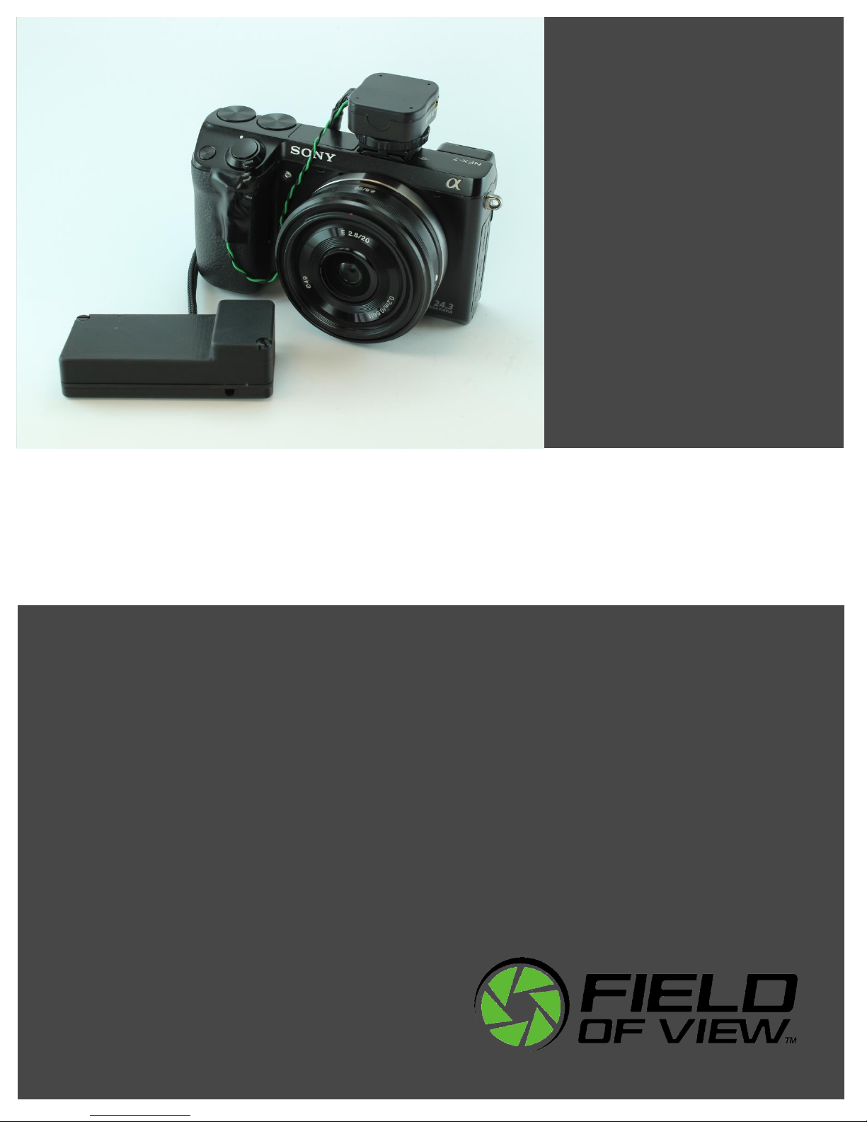
The GeoSnap Express
The Field of View GeoSnap system was developed to streamline camera payload integration,
facilitate intelligent triggering, and produce a valuable log of position and ground track heading
conditions at the moment of image capture.
System components
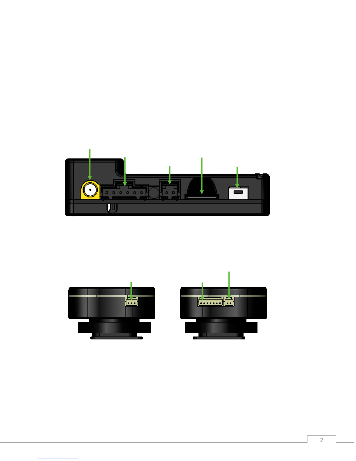
GeoSnap Control Unit
GeoSnap Hotshoe Module
GPS antenna port
Power input
MicroSD card slot
Onboard button
6-position I/O port
Wired trigger port
Control unit port
IR LED port

© Field of View 2016 GeoSnap Express User Manual
Introduction
3 3
Wired trigger pigtail
Velcro mounting patch
IR trigger cable
MicroSD card adapter
Power pigtail
6-position housing
6-position I/O wires
GPS antenna
Accessories

© Field of View 2016 GeoSnap Express User Manual
4 4 4 4 4 4
Getting Started
In this section:
Installing the GeoSnap system
Using the wired remote trigger
Using the 6-position I/O port
Powering the GeoSnap system
LED codes
Loading new firmware onto the GeoSnap system
© Field of View 2016 GeoSnap Express User Manual
Getting Started
5 5
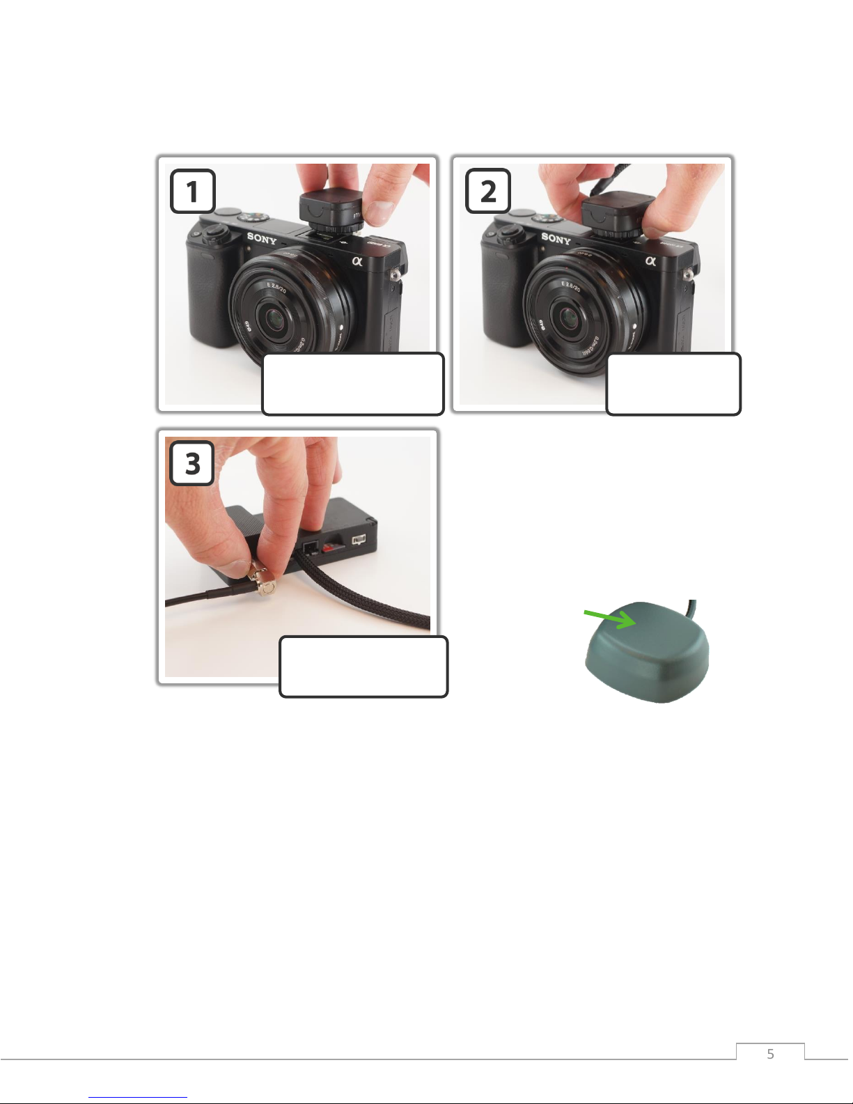
Installing the GeoSnap Express on a DSLR camera
Place the hotshoe module
onto the camera’s hotshoe
mount
Tighten down the
hotshoe module by
twisting the lock
Screw down the GPS
antenna SMA connector
so that it is snug
Note: Make sure you mount the GPS
antenna with the top facing up and with
a clear view of the sky. Also make sure
that you do not mount the antenna near
transmitters on the aircraft that could
cause interference and degrade the
performance of the GPS.
TOP
© Field of View 2016 GeoSnap Express User Manual
Getting Started
6 6
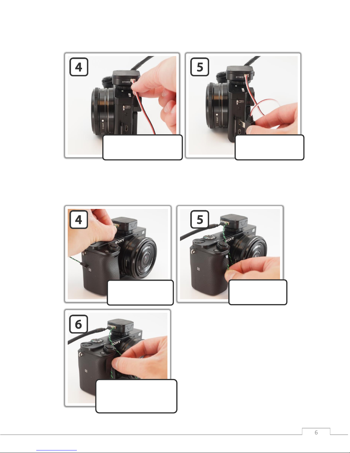
If using the hardwire trigger cable
Note: The standard GeoSnap kit comes with a trigger wire pigtail cable that you need to
integrate with the appropriate hardwire trigger plug for your camera. The images above show a
GeoSnap trigger cable that is integrated with a Sony A6000 trigger plug
If using the IR LED trigger cable
Plug the IR LED cable
into the IR LED port on
the hotshoe module
Route the IR LED
cable to the remote
control sensor
Attach the IR LED to the
camera over the remote
control sensor (you can do
this by using a piece of tape)
Plug the 3-pos trigger cable
into the wired trigger port on
the hotshoe module
Route the cable to the
wired trigger port on the
camera and plug it in

© Field of View 2016 GeoSnap Express User Manual
Getting Started
7 7
Using the wired remote trigger
You can trigger the camera via a wired remote port if your camera has one. There is a wired
trigger pigtail cable and/or custom wired trigger cable provided for this purpose. This cable
plugs into the 3-position wired trigger port. If you are interfacing with the camera using the
wired trigger pigtail, it is recommended that you follow these steps:
1. Purchase a stock wired remote for your particular camera model
2. Cut the cable 1-5” from the connector depending on the location of the wired remote
port relative to the GeoSnap hotshoe module
3. Strip the ends of the stock wired remote cable wires
4. Identify which cables in the stock cable relate to Ground, Focus, and Shutter Release
5. Connect the wires to the wired trigger pigtail as follows: Ground -> Black, Focus ->
White, and Shutter Release -> Green
6. Plug the cable into the camera and the GeoSnap hotshoe module
Using the 6-position I/O port
The 6-position I/O port can be used to interface with the GeoSnap system primarily to control
triggering using an external source. A 6-position locking connector and wires with pre-crimped
pins are provided in the GeoSnap system accessories. To install a wire into the 6-position locking
connector, place the wire into the appropriate slot in the 6-position connector with the smooth
side of the pin facing up. Push the wire in until you hear a click then tug on it slightly to ensure
that it seated.
6-Position I/O Port Pinout
Pin
Label
Voltage
Description
1
Ground
-
-
2
N/A
- - 3
N/A
- - 4
Trigger
0 to 5V
Control GeoSnap by driving this line high or low
5
Indication
0 or 3.3V
Line goes high when capture verification is received
6
VCC
3.3V
-
Triggering
The GeoSnap board can be triggered externally by an autopilot or other input by driving the
Trigger line (position 4) high (3.3-5V) or low (0-0.2V), depending on the settings you have chosen
in the configuration file. It is highly recommended that you use the GeoSnap system VCC line
(position 6) to provide the voltage to hold or drive the Trigger line high. Triggering using the
Trigger line and the VCC line can be accomplished by shorting the two wires together or by using
a PWM relay to control voltage level.

© Field of View 2016 GeoSnap Express User Manual
Getting Started
8 8
Indication
You may also interface with the Indication line (position 5) to receive indication when the
camera has taken a picture. The voltage in this line goes high (3.3-5V) when capture verification
is received from the camera.
Ground & VCC
If an external device (i.e. an autopilot) is being used to command a trigger through the Trigger
line (position 4) on the GeoSnap system as described above, it is highly recommended that the
external device and the GeoSnap system are powered by the same source. If this is not the case
(e.g. the external device and the GeoSnap system are powered by two separate batteries), the
ground pin on the autopilot and the Ground line (position 1) on the GeoSnap system should be
connected so that there is a common ground for triggering purposes.
The VCC line (position 6) should not be used to power any external devices. It should be used
only for triggering with the Trigger line (position 4) as described above.
Powering the GeoSnap system
When it comes time to power the system, plug either the provided 9V battery holder or the
provided power pigtail cable connected to an appropriate power source into the GeoSnap
control module power input port.
GeoSnap Express Power Requirements
Parameter
Value
Voltage input range
4.5 to 28 V
Current input (typical)
0.10 A
Loading new firmware onto the GeoSnap system
If you need to load new firmware on your GeoSnap system, follow these steps:
1. Erase all data from the microSD card
2. Copy the firmware file (FOV.fwu) onto the microSD card and insert the card into the
GeoSnap system
3. Power the GeoSnap system – it will flash alternating red and green LEDs for a couple of
seconds until the firmware is loaded and it automatically erases the firmware file from
the microSD card

© Field of View 2016 GeoSnap Express User Manual
Getting Started
9 9
LED codes
The meanings of the LEDs on the GeoSnap board are explained in this section.
Blue LED – This LED indicates when the board is powered. When power is sent to the
board, this LED shines solid.
Red LED & Green LED – These LEDs indicate the status of the GeoSnap system including
startup status, GPS status, triggering, and camera capture indications.
A detailed description of the LED sequences and their meanings are presented below.
Red and Green LED Codes
Startup Sequence
LED Code
Meaning
Board is checking for access to the microSD card and writing a
default CONFIG file to the card if a CONFIG file does not already
exist. *Note: this is also the LED code for an SD card error (see
below) so if this pattern persists, check the SD card.
No GPS lock but system is ready to start operating. If the GeoSnap
system is configured for fast as possible or time based triggering,
the first trigger command will be sent at this point
GPS lock. If the GeoSnap system is configured for distance based
triggering, the first trigger command will be sent 10s after GPS lock
is obtained.
This occurs after pressing and holding the trigger button for
approximately 3 seconds. This signifies that all data logging has
stopped and it is safe to power down the system.
Capturing Images
LED Code
Meaning
A trigger command has been sent
Capture confirmation received from camera
Errors
LED Code
Meaning
MicroSD card error. Occurs when there is no card, the card is not
seated properly, the card is full, or if the log file number exceeds
999.

© Field of View 2016 GeoSnap Express User Manual
10 10 10 10 10 10
GeoSnap System Files
In this section:
Imagenum file
Configuration file
Flight data log file
Image log file
Pix4D log file

© Field of View 2016 GeoSnap Express User Manual
GeoSnap System Files
11 11
Imagenum file
The GeoSnap system stores a text file on its microSD card called IMAGENUM.TXT. This file keeps
track of where the GeoSnap left off numbering the images in the IMG log file between power
cycles. If you want to restart the GeoSnap image numbering at 1, simply delete the IMAGENUM
file from the GeoSnap microSD card. For more information on synchronizing the camera and
GeoSnap file names, see the Camera settings section.
Configuration file
The CONFIG.TXT file is where you can adjust all of the settings of the GeoSnap. Each time the
GeoSnap system is powered, it searches for the configuration file and reads the settings. If this
file is not present, the GeoSnap system creates a new configuration file with default options.
The file consists of human-readable ASCII text and can be edited using many types of text
editors. On Windows, either Notepad or Wordpad may be used. On OSX, TextEdit may be used.
On GNU/Linux or Unix, EMACS, Vim, Nano, Pico, or other graphical equivalents may be used.
Note: word processing software such as Microsoft Word should not be used to edit the
configuration file.
The first line of the CONFIG file displays which GeoSnap system firmware generated the file. The
sections below describe in detail the various settings and how their options/values affect the
behavior of the GeoSnap system.

© Field of View 2016 GeoSnap Express User Manual
GeoSnap System Files
12 12
Brand-specific infrared LED trigger code
Default String:
@1:IR_LED_code = 0
Values:
0: none (wired shutter release only) [default]
1: Canon
2: Sony
3: Nikon
Description:
This option controls the code that is output by the IR LED to trigger the camera. Different
brands of cameras recognize different IR LED codes so it is very important to set this option
to the brand of camera that you are using. If you are using the wired shutter release to
trigger the camera, the camera brand is irrelevant.
Image file name convention
Default String:
@2:File_name = 0
Values:
0: none specified [default]
1: IMG_0001.JPG (Canon)
2: DSC00001.JPG (Sony)
3: DSCN0001.JPG (Nikon)
4: DSCF0001.JPG (Fuji)
5: DSC_0001.JPG (Nikon)
Description:
This option allows you to specify what will be entered into the “image” column in the image
log file. If option ‘0’ is selected, the “image” entry in the image log file will be filled with an
image counter that can be converted to image names in post-processing using Geotility. If
an actual image name is selected the “image” entry in the image log file will be filled with
consecutively numbered image names. For example, if option ‘1’ is selected, the entries in
the “image” column will take the form of IMG_0001.JPG, IMG_0002.JPG, etc.

© Field of View 2016 GeoSnap Express User Manual
GeoSnap System Files
13 13
Mode that determines when the GeoSnap system sends a trigger
command
Default String:
@3:Trigger_mode = 0
Values:
0: onboard button only [default]
1: time
2: distance
3: fast-as-possible
4: low->high input signal
5: high->low input signal
6: low->high and high->low input signal
7: Garmin portable aviation GPS waypoint arrival/time interval
Description:
Set this option to specify the mode that the GeoSnap system will use to determine when to
send a trigger command.
Onboard button only: a trigger command is sent when the GeoSnap system’s
onboard button is pushed.
Time: trigger commands are sent at a uniform time interval that can be specified in
the time interval option.
Distance: trigger commands are sent at a uniform distance interval (calculated from
the latitude and longitude obtained from the GPS) that can be specified in the
distance interval option.
Fast-as-possible: a trigger command is sent immediately after the GeoSnap system
receives capture verification from the camera resulting from the prior trigger
command.
Any of the input signal modes (options 4, 5, and 6): a trigger command is sent every
time the external input signal sends a voltage transition as listed in the option. For
example, if ‘low->high input signal’ is selected, the GeoSnap will send a trigger
command every time the external input signal transitions from low to high voltage
(for more information on using an external input signal, see the “Using the 6position I/O port” section).
Garmin portable aviation GPS waypoint arrival/time interval: a trigger command is
sent every time a waypoint that is set in a Garmin portable aviation GPS is reached.
It will also send a trigger command at the specified time interval when the switch on
the handheld remote (part of the Garmin portable aviation GPS GeoSnap solution) is
in the always on position.

© Field of View 2016 GeoSnap Express User Manual
GeoSnap System Files
14 14
For mode 1 or 7 above, specify a time interval in seconds
Default String:
@4:Trigger_time_sec = 2.0
Values:
0.1 - 64800 seconds (in tenth of a second increments)
Description:
This option sets the amount of time (in seconds) between trigger commands sent by the
GeoSnap system when it is set to time mode triggering or when the handheld remote switch
is set to the always on position in a Garmin setup. This is configurable in tenth of a second
increments. The trigger mode must be set to 1 or 7 in order for this option to have any
effect on system operation.
For mode 2 above, specify a distance interval in meters
Default String:
@5:Trigger_dist_m = 50
Values:
1 - 10000 meters (in meter increments)
Description:
This option sets the distance (in meters) between trigger commands sent by the GeoSnap
system when it is set to distance mode triggering. This is configurable in meter increments.
Any decimals entered will be truncated. The trigger mode must be set to 2 in order for this
option to have any effect on system operation.
Length of time the GeoSnap system waits for capture verification from
the camera before resending the trigger command
Default String:
@6:Resend_trig_time_ms = 500
Values:
0 - 60000 milliseconds
Description:
This option allows you to set the amount of time the GeoSnap system waits for capture
verification before resending the trigger command. This value should be greater than or
equal to the cycle time of the camera. This option gives you control over your mission
quality control by allowing you to specify the amount of time to wait and see if the camera
took a picture before identifying a missed trigger and attempting to salvage the trigger
point.

© Field of View 2016 GeoSnap Express User Manual
GeoSnap System Files
15 15
Use external input signal or onboard button to control time mode, fast-aspossible mode, and/or distance mode
Default String:
@7:Control_mode= 0
Values:
0: feature disabled [default]
1: high input signal enables time mode, fast-as-possible mode, or
distance mode
2: low input signal enables time mode, fast-as-possible mode, or
distance mode
3: onboard button starts time mode or fast-as-possible mode
4: onboard button toggles (starts/stops) time mode or fast-as
possible mode
Description:
This option allows you to use an external input signal to enable time mode, fast-as-possible
mode, or distance mode or to use the GeoSnap system onboard button to start and/or stop
time mode or fast-as-possible mode. If this feature is disabled and the GeoSnap system is in
time, or fast-as-possible mode, it will start sending trigger commands as soon as it is
powered. If this feature is disabled and the GeoSnap system is in distance mode, it will start
sending trigger commands as soon as a GPS lock is acquired.
If enabling with an input signal is selected (options 1 or 2), time mode, distance mode, or
fast-as-possible mode triggering, will only be allowed when the external input signal is held
high or held low (depending on the option selected). This is useful if images are only desired
during a certain portion of the flight.
If option 3 is selected, time or fast-as-possible triggering won’t start until the button is
pressed and subsequent button presses will be ignored. If option 4 selected, time or fast-aspossible triggering won’t start until the button is pressed and subsequent button presses
will stop and start the triggering.

© Field of View 2016 GeoSnap Express User Manual
GeoSnap System Files
16 16
Activate time mode or fast-as-possible mode when the GeoSnap system
detects an initial image capture
Default String:
@8:Initial_image_activation = 0
Values:
0: feature disabled [default]
1: feature enabled
Description:
This option configures whether to start time mode or fast-as-possible mode triggering after
an initial camera image capture has been detected by the GeoSnap system. This initial image
capture could be initiated using the shoulder button on the camera or with an external
signal input.
Send trigger command at least every X minutes to prevent camera liveview timeout
Default String:
@9:Elapsed_time_min = 0
Values:
0 – 600000 min
Description:
This option is designed for use with manned aircraft setup with Canon Live-View. The Canon
kicks out of Live view mode after a period of activity. This option allows you to have the
GeoSnap keep track of length of inactivity (i.e. no camera triggers) and send a trigger
command at the specified number of minutes if no activity has happened. For example, if
you set the value to 10 and there were no images taken after 10 minutes, the GeoSnap
would command a trigger at that point. To disable this feature, simply set the value to 0.

© Field of View 2016 GeoSnap Express User Manual
GeoSnap System Files
17 17
Only allow time mode, distance mode, or fast-as-possible mode above a
specified WGS84 altitude
Default String:
@13:Enable_altitude_limit = 0
Values:
0: feature disabled [default]
1: feature enabled
Description:
This option allows you to constrain the GeoSnap system so that it pauses image triggering
when the aircraft is below a certain WGS-84 altitude. Any time mode, distance mode, or
fast-as-possible mode triggering will only be allowed when the aircraft is above a specified
altitude. This is useful to prevent image capture while the aircraft is on the ground.
WGS84 altitude limit
Default String:
@14:Minimum_altitude_m = 50
Values:
1 - 65536 meters (to the nearest meter)
Description:
This option configures the altitude limit associated with the altitude limit option. The
altitude limit option must be enabled for this to take effect. This is configurable in one
meter intervals only. Any decimals entered will be truncated.
Associate and log position/attitude data at the moment the trigger
command is sent, not when capture verification is received
Default String:
@15:Blind_logging = 0
Options:
0: feature disabled [default]
1: feature enabled
Description:
This option allows you to ignore capture verification completely and associate and log
position/attitude data at the time that the trigger command is sent. Since capture
verification is ignored when blind logging is enabled, if you are in fast-as-possible mode the
GeoSnap system will send a trigger command at the interval specified in the
Resend_trig_time_ms option (option @6).

© Field of View 2016 GeoSnap Express User Manual
GeoSnap System Files
18 18
Associate position/attitude data with the image ‘x’ milliseconds after
capture verification is received
Default String:
@16:Association_delay_ms = 0
Description:
This option allows you to add a delay between when the GeoSnap system received capture
verification and when the position/attitude association is performed and written to the
image log file.
Select which log files to generate
Default String:
@17:Data_logging = 0
Options:
0: generate image log, pix4d log, and flight data log [default]
1: generate image log and flight data log only
2: generate image log and pix4d log only
3: generate image log only
Description:
This option configures whether or not to create and populate the IMG, P4D, and/or FLT log
files on the GeoSnap system’s onboard microSD card.
Set up which way your camera is oriented relative to the direction of
flight
Default String:
@27:Camera_install_orientation = 0
Values:
0: camera top facing forward [default]
1: camera left facing forward
2: camera bottom facing forward
3: camera right facing forward
Description:
This option allows you to configure how the yaw value is saved in the GeoSnap log files.
Refer to the images below to decide which option fits your camera installation orientation.

© Field of View 2016 GeoSnap Express User Manual
GeoSnap System Files
19 19
Top forward Left forward Bottom forward Right forward
Flight data log file
The FLT.txt file is a 25Hz log of the position of the camera throughout the flight. Files over 3
million lines are prevented to assure timely logging to the microSD card. After 3 million lines a
new FLT file is created with a letter appended to it with the following convention: 001-FLT.txt,
001-FLTA.txt, 001-FLTB.txt, 001-FLTC.txt, etc. Information is logged as plain, ASCII text in spaceseparated columns; each column is exactly 14 characters wide.
Direction of flight

© Field of View 2016 GeoSnap Express User Manual
GeoSnap System Files
20 20
Flight Data Log File Columns
Column
Label
Units
Description
1
utcdate
YYYY-MM-DD
Date as reported by the ublox
2
utctime
HH:MM:SS
UTC time as reported by the ublox
3
lat(deg)
degrees
Latitude as reported by the ublox
4
lon(deg)
degrees
Longitude as reported by the ublox
5
hght(wgs84-m)
meters
Height above WGS84 ellipsoid
6
roll(deg)
degrees
The GeoSnap Express does not log roll
data so this column is just zeros
7
pitch(deg)
degrees
The GeoSnap Express does not log pitch
data so this column is just zeros
8
yaw(deg)
degrees
Ground track heading of the system as
reported by the ublox
9
gstime(ms)
milliseconds
GeoSnap time since power on
10
horz_accy(m)
meters
Horizontal position uncertainty of the
ublox
11
vert_accy(m)
meters
Vertical position uncertainty of the ublox
12
fix_status
Status of the GNSS fix as reported by the
ublox
Image log file
The IMG.txt file is a log of the image name and position of the camera at the moment of image
capture. Information is logged as plain, ASCII text in space-separated columns; each column is
exactly 14 characters wide.
Image Log File Columns
Column
Label
Units
Description
1
image
name
Image name/counter
2
utcdate
YYYY-MM-DD
Date as reported by the ublox

© Field of View 2016 GeoSnap Express User Manual
GeoSnap System Files
21 21
3
utctime
HH:MM:SS
UTC time as reported by the ublox
4
lat(deg)
degrees
Latitude as reported by the ublox
5
lon(deg)
degrees
Longitude as reported by the ublox
6
hght(wgs84-m)
meters
Height above WGS84 ellipsoid
7
roll(deg)
degrees
The GeoSnap Express does not log roll
data so this column is just zeros
8
pitch(deg)
degrees
The GeoSnap Express does not log pitch
data so this column is just zeros
9
yaw(deg)
degrees
Ground track heading of the system as
reported by the ublox
10
gstime(ms)
milliseconds
GeoSnap time since power on
11
horz_accy(m)
meters
Horizontal position uncertainty of the
ublox
12
vert_accy(m)
meters
Vertical position uncertainty of the ublox
13
fix_status
Status of the GNSS fix as reported by the
ublox
Pix4D log file
The P4D.txt file is a Pix4D compatible log of the image name and position of the camera at the
moment of image capture. Information is logged as plain, ASCII text in comma-separated
columns.
Pix4D Log File Columns
Column
Label
Units
Description
1
imagename
name
Image name/counter
4
latitude
degrees
Latitude as reported by the ublox
5
longitude
degrees
Longitude as reported by the ublox
6
altitude
meters
Height above WGS84 ellipsoid

© Field of View 2016 GeoSnap Express User Manual
22 22 22 22 22 22
Troubleshooting
In this section:
GPS signal quality test
Fix status code lookup table

© Field of View 2016 GeoSnap Express User Manual
Troubleshooting
23 23
GPS signal quality test
There are a variety of transmitters and components on an aircraft that can degrade the GPS
signal received by the antenna if it is placed in a poor spot and cause you to log poor GPS data in
your FLT and IMG log files. Because of this, it is best to test your setup for GPS signal quality
after installing your GeoSnap system on your aircraft.
Basic test
To run a quick test to identify if you are getting good GPS data, perform the steps outlined in
this section.
Set the GeoSnap system to the bench test settings (i.e. button toggle).
With everything installed on your aircraft, place it outside in an area that has a clear
view of the sky (i.e. in a clear open area, not near tall buildings, trees, or power lines).
Power on the GeoSnap system and wait for it to get a GPS lock (signified by the green
LED on the GeoSnap control module flashing rapidly).
Start image triggering on the GeoSnap system by pressing the onboard button.
Power on the rest of the systems on the aircraft (including any video transmitters) on
the aircraft and, if using a multicopter, set the motors to idle (make sure you take
appropriate safety measures around the spinning propellers).
Let the system sit for 3-5 minutes to allow the GPS on the GeoSnap system to stabilize
and to get a good dataset.
Power everything down.
Remove the GeoSnap system’s microSD card, plug it into your computer and open the
FLT log.
Look at the horz_accy column in the FLT log. It should start out with fairly high
uncertainties (≈15-20m) that rapidly decrease and stabilize at uncertainties ≤2m (ideally
≤1m).
If the horz_accy stabilizes at a value greater than 2m, there is likely some interference
happening with the GPS signal and further testing will have to be performed to identify
what on the aircraft may be causing the issue.
Identification test
If you are getting poor GPS data (i.e. horz_accy > 2m), run the test outlined below to identify
what system(s) on your aircraft are causing a degradation of the GPS data.
Set the GeoSnap system to the bench test settings (i.e. button toggle).
With everything installed on your aircraft, place it outside in an area that has a clear
view of the sky (i.e. in a clear open area, not near tall buildings, trees, or power lines).
Power on the GeoSnap system and wait for it to get a GPS lock (signified by the green
LED on the GeoSnap control module flashing rapidly).

© Field of View 2016 GeoSnap Express User Manual
Troubleshooting
24 24
With everything except the GeoSnap still powered off, let the system sit for 3-5 minutes
to allow the GPS on the GeoSnap system to stabilize and to get a good baseline dataset.
Power on the rest of the systems on the aircraft and press the GeoSnap onboard button
twice to turn on and off triggering (this is to trigger one image to act as a timestamp to
mark when you powered on the rest of the systems).
Let the system sit for 3-5 more minutes with everything powered on.
If using a multicopter, trigger another single image (to act as another timestamp) with
the GeoSnap by pressing the onboard button twice, then set the multicopter motors to
idle (making sure you take appropriate safety measures around the spinning propellers).
Let the system sit for another 3-5 minutes with everything powered on and the motors
running.
At this point, use the button on the GeoSnap to start triggering (if using a multicopter,
turn off the motors if necessary to safely access the GeoSnap then, once the triggering is
started, set the motors back to idle).
Let the system sit for 3-5 more minutes with everything powered on, the motors
running, and the camera taking images.
Power everything down.
Remove the GeoSnap system’s microSD card, plug it into your computer and open the
IMG and FLT logs.
In the IMG log, make note of the gstime (located after the yaw column) of the first three
images (i.e. when you powered on the rest of the systems, when you started the
motors, and when you started triggering).
In the FLT log, look at the horz_accy column. It should start out with fairly high
uncertainties (≈15-20m) that rapidly decrease and stabilize at uncertainties ≤2m (ideally
≤1m) when just the GeoSnap is powered on.
Scroll down until you find the gstime in the FLT log that corresponds to when the rest of
the systems on the aircraft were powered on. Look at the horz_accy column to see if the
uncertainties increase noticeably after that point.
Do the same process with the gstimes corresponding to when the motors were started
and when camera triggering was started.
If the uncertainties increase noticeably after any of the marked occurrences (i.e.
systems powered on, motors started, or camera triggering started), perform the GPS
test again with the corresponding system not operating (e.g. if there was an increase in
horz_accy after the motors were turned on, place the aircraft outside with all of the
systems powered on and the camera triggering but with the motors turned off).
If the resulting uncertainties are ≤2m, then you know that the GPS issue is coming from
the identified problem (in this example, the motors being powered).
Try moving the GPS antenna to a better location on the aircraft, away from any
components that may be causing the interference, and re-run the test, looking for ≤2m
uncertainties. Or, if the interference appears to be coming from an expendable system

© Field of View 2016 GeoSnap Express User Manual
Troubleshooting
25 25
(e.g. a video transmitter that doesn’t need to be running during the flight), try turning
off that system and re-running the test, looking for ≤2m uncertainties.
Fix status code lookup table
Fix Status Lookup Table
Value
Description
00
No GNSS fix
01
Dead reckoning only
02
2D fix
03
3D fix

© Field of View 2016 GeoSnap Express User Manual
26 26 26 26 26 26

© Field of View 2016 GeoSnap Express User Manual
Specifications & Settings
27 27
Specifications & Settings
In this section:
Physical specifications
Power specifications
6-position I/O port specifications
MicroSD card specifications
Camera settings
GeoSnap Express and DSLR Checklist

© Field of View 2016 GeoSnap Express User Manual
Specifications & Settings
28 28
Physical specifications
GeoSnap Express (DSLR) hotshoe module dimensions (in millimeters).
GeoSnap Express control unit dimensions (in millimeters).

© Field of View 2016 GeoSnap Express User Manual
Specifications & Settings
29 29
GeoSnap Express (DSLR) Weights
Component
Weight
Control unit (with microSD card)
32 g
Hotshoe module
14 g
Cabling
6 g
GPS antenna w/ 0.75m cable
40 g
Total system weight
92 g
Power specifications
GeoSnap Express (DSLR) Power Requirements
Parameter
Value
Voltage input range
4.5 to 28 V
Current input (typical)
0.10 A
6-position I/O port specifications
6-Position I/O Port Pinout
Position
Label
Voltage
Description
1
Ground
- - 2
RS232-in
-15 to 15V
Not currently operational
3
RS232-out
-15 to 15V
Not currently operational
4
Trigger
0 to 5V
Control GeoSnap system by driving this line
high or low
5
Indication
0 or 3.3V
Line goes high when capture verification is
received
6
VCC
3.3V
-

© Field of View 2016 GeoSnap Express User Manual
Specifications & Settings
30 30
MicroSD card specifications
The MicroSD Flash Storage Card (microSD card for short) is used to log flight telemetry and
image telemetry data on-board the GeoSnap system control unit. The card used must meet the
following requirements:
MicroSD ( SDHC)
Sandisk Ultra MicroSD recommended
System successfully tested with 4GB, 8GB, and 16GB SDHC cards
Formatted as FAT32 (exFAT is not supported)
To use a new microSD card in the GeoSnap system, make sure it meets the requirements above
and is blank. Insert the card into the system, power on and wait for a couple seconds, then
power down and remove the card. The card will have been populated with a default CONFIG file
that you can then edit to your requirements.
Camera settings
To obtain good aerial images when performing a mission using the GeoSnap system it is
necessary that certain settings be applied to your camera. The following table addresses the
required and recommended camera settings to help ensure successful imaging missions. Refer
to your camera manual for information on how to adjust these settings.
Required Settings
Setting
Value
Description
Drive Mode
Remote control
Required for triggering the camera using the
IR LED or the wired remote
Focus Drive
Manual focus
-
Focus Distance
Infinity
Set the focus so objects are sharp at infinity
and lock down the lens in that position by
using a piece of tape or something similar
Shoot Mode
Shutter priority
-
Shutter Speed
1/1000 or faster
Required for sharp images while the aircraft is
in motion
Recommended Settings
Setting
Value
Description
Flash Mode
No flash
-
ISO
Auto
-
White Balance
AWB
-
Shading/Peripheral
Enable/Auto
Enable any shading or peripheral illumination

© Field of View 2016 GeoSnap Express User Manual
Specifications & Settings
31 31
Illumination
correction option
Chromatic
Aberration
Enable/Auto
Enable any chromatic aberration correction
option
Distortion
Enable/Auto
Enable any distortion correction option
File name synchronization
The GeoSnap and the camera both handle image numbering separately (i.e. the GeoSnap does
not get the actual image names from the camera but just logs the correct image name format
with a sequential numbering scheme). Because of this, it is important that the camera and the
GeoSnap be set up so that they both start numbering the images at 1 and remain synchronized
through use.
The GeoSnap system keeps track of the image name count between power cycles using the
COUNT.SYS file that is on the GeoSnap microSD card. If you want to restart the GeoSnap image
numbering at 1, simply delete the COUNT.SYS file off of the GeoSnap microSD card.
DSLR style cameras typically have two main options to handle file numbering. (The Canon 6D has
Continuous and Auto Reset; the Sony A6000 has Series and Reset). Continuous/Series file
numbering continuously numbers the images, even between power cycles or between cards,
etc. When the file numbering is set to Continuous, the Canon 6D has an option to reset the
numbering back to 1 by selecting the Manual Reset option. This will reset the numbering back to
1 then return to continuously numbering the images from there. The Sony A600, however, does
not have a Manual Reset option. Auto Reset/Reset file numbering resets the file numbering to 1
anytime that there is an SD card inserted that has no images on it or that the camera card is
formatted.
Method 1
The recommended method for handling file name synchronization is to set the camera’s file
numbering setting to Auto Reset. Then, before you start a new mission, clear all images off of
the camera’s SD card and delete the COUNT.SYS file off of the GeoSnap card. This will reset both
systems to start image numbering at 1.
Method 2 (only for Canon 6D)
(Note: This method requires unobstructed access to the camera screen and menu buttons.)
Alternatively, you can set the Canon’s “File numbering” option to Continuous and do a Manual
Reset to start it at 1. You would then delete the COUNT.SYS file off of the GeoSnap, to start it at
1, but then not delete the COUNT.SYS file after that. Both the camera and GeoSnap would then
continue numbering between flights. However, if there was the need to reset numbering to 1
(e.g. the COUNT.SYS file was accidentally deleted off of the GeoSnap card or image numbers hit
9999 and reset) then you would need to synchronize the numbering again by deleting the
COUNT.SYS file and then doing a Manual Reset on the camera’s file numbering to get both of
them synchronized back to 1.

© Field of View 2016 GeoSnap Express User Manual
Specifications & Settings
32 32
GeoSnap Express and DSLR Checklist
GeoSnap Express file setup
□ IR LED code (or wired trigger)
□ File name type (Sony, Canon, etc)
□ Trigger mode (distance, time, etc)
□ Trigger mode parameter (# meters or # seconds)
□ Resend trigger time (typically around 750ms)
□ Control mode (none, button toggle, etc)
□ Camera orientation (top forward, bottom forward, etc)
□ Delete IMAGENUM.txt file off of the card if you want the IMG file to start at 1
DSLR setup
□ Insert fully charged battery into camera
□ Insert empty SD card into camera
□ Make sure all of the settings are correct
o Shutter priority, 1/1000s (shutter speed)
o ISO Auto
o White Balance Sunny/Cloudy
o MF (Manual Focus) – lens taped down and focused at infinity
o Single capture – remote shooting
o Large image quality
Pre-flight system checks
□ Lens cap is off of camera and lens is clean
□ Hotshoe module is on the camera and tightened down
□ GeoSnap/camera trigger cable is in place and secure
□ GeoSnap microSD card is in the GeoSnap control module
□ GeoSnap GPS antenna is screwed on and antenna is mounted securely
□ Camera/GeoSnap are securely mounted on aircraft
Powering the system
□ Power on DSLR
□ Plug in the GeoSnap Express
□ Watch for GPS lock on GeoSnap Express (green LED will start flashing quicker)
□ If in distance trigger mode, watch for first trigger (10sec after GPS lock is obtained)
□ Take-off
Post-flight
□ Press and hold GeoSnap onboard button to stop logging
□ Power down GeoSnap and DSLR
□ Remove GeoSnap microSD card and DSLR SD card
 Loading...