

FieldLogix GPS Device Installation Instructions Manual
Soldering tool and solder
Voltage Meter
Zip Ties
A. GPS
B. Power
C. GPS
D. Navigation
Table of Contents
Item
Page
GPS Device Installation Instructions
You will need the following tools:
•
Crimp ring terminal • Electrical Tape • Silicone Glue
•
•
Torque Seal • Wire strippers • Wire crimpers
•
•
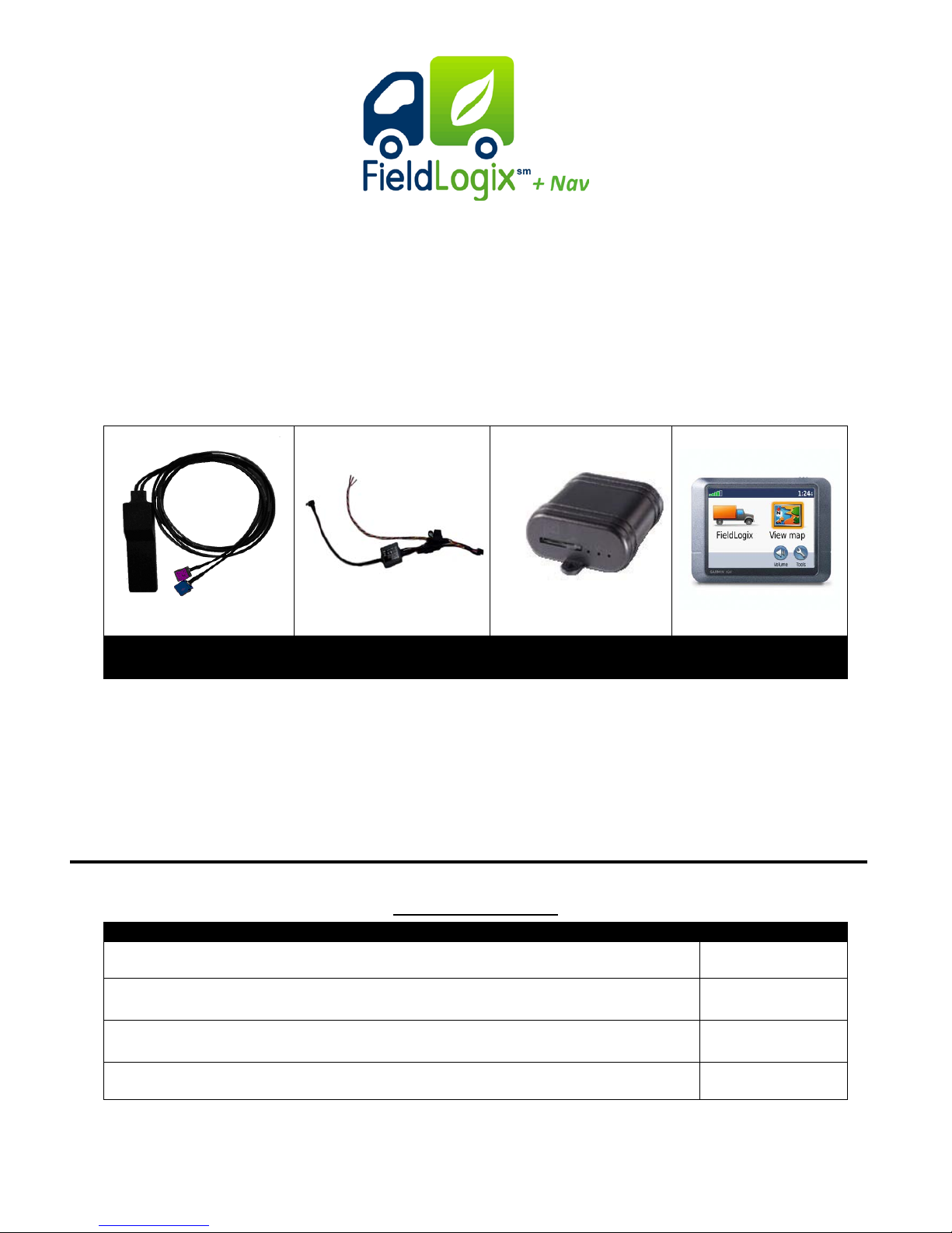
There are 4 components to the GPS device:
Antenna
Harness
Device
The above components must be installed in the following order:
A. GPS / Cell combo antenna
B. Power harness
C. GPS device
D. Garmin Navigation Device
Device
GPS / Cell Combo Antenna Install at ion Procedure 2
Power Harness Installation Procedure 3
GPS Device Installation Procedure 5
Device Testing & Troubleshooting Procedure 6
Copyright © 2010 FieldLogix 888-803-0200
1
support@fieldtechnologies.com
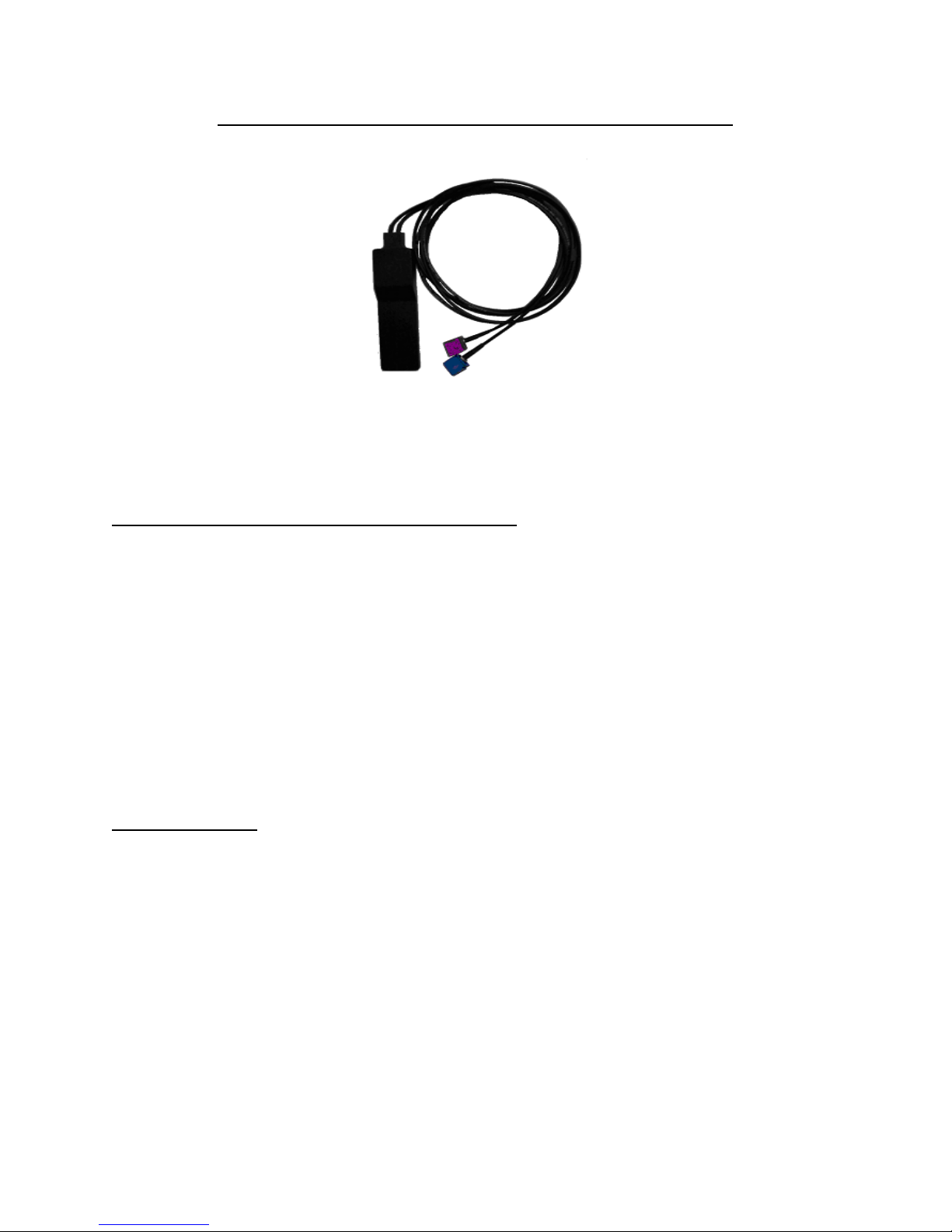
A. Installing the Combo GPS / Cellular Antenna
Mount the antenna in the specified location (see below) and run the antenna leads to the
planned location of the GPS device. The standard location is underneath the dashboard.
Only perform a roof mo unt installation if you c annot meet the specif ications requi red in the
under dashboard installation or if specified on the work order.
1. Under dashboard installation - Standard:
Mount the antenna in a location underneath the dashboard. Be sure to follow the points
below:
• The top (side that has th e arch) of the antenna must face up toward the sky.
• The antenna should be hidd en and must hav e direct line of sight to th e sky through
the windshield.
• The antenna cannot be mounted underneath metal as this will interfere with the
GPS signal.
• Make sure that the ant enna is not beneath a portion of the wi ndshield that has a
metal film or tint as this will block the signal.
• Do not crimp or route antenna cables.
• Use the adhesive or silicone glue to secure the bottom of the antenna to its
location.
2. Roof mount:
Only install a roof mount antenna if specified on the work order or if you cannot find a
suitable location underneath the dash board.
Drill a 3/4 inch hole in the front l eft corner of the roof of the ve hicle, just over the A-pillar.
Run the antenna leads thr ough the hole down the A-pilla r to the device. Mount the GP S
antenna to the roof using silicone glue and use silicone on the drilled hole to ensure that
there are no leaks.
***You must ensure that any drilled holes are sealed properly***
Copyright © 2010 FieldLogix 888-803-0200
2
support@fieldtechnologies.com
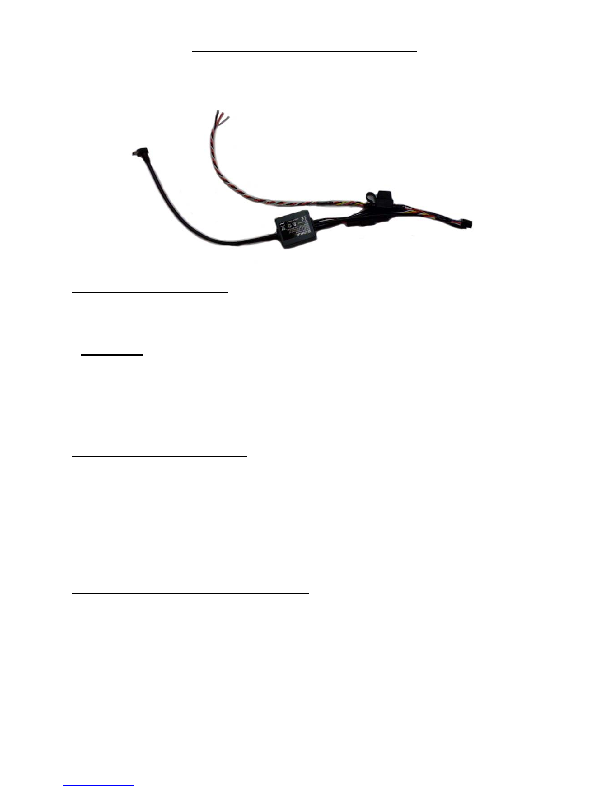
B. Installing the wiring ha rness:
This type of harness has three wires. The Red wire is for constant power, the White wire is
for ignition, and the Black is for ground.
Do not plug harness into devi ce when makin g connections !
Searching for Correct Wir es :
In order to find to correct wires, you must first set your multi meter to DCV or DC voltage
12V or 20V, attach the negative (-) probe to the vehicle chassis ground, and then begin
probing the wires you suspect of being the constant and ignition pow er s ourc es .
Important: When searching for the correct wires, DO NOT use a test bulb circuit tester.
Often, damage to vehicle computers and vehicle air bag restraint systems result from the
use of a test bulb causing a short circuit. Ideally, the use of a digital multi meter is the best
tool to search for the correct wires.
The appropriate power wires should be found in the vehicle’s ignition harness
(See Chart A for the most common color codes for most vehicles)
How to Find Constant Power:
Locate the wire that yo u suspec t would h ave cons tant pow er. Pro be the w ire wit h the met er
lead. T urn the v ehicle’s ignition o n and off w hile met ering the wire. Th is wire shou ld read a
constant 12 volts or higher when the ignition is in both the “ON” and “OFF” positions.
Strip the insulation back and connect the red wire from th e tracking unit’s harness to this
constant wire using the hook and wrap technique (See dia gram A on the following page).
Solder the conn ection to ensure a quality contact. Refer t o Chart A for the most common
colors for a constant power connection.
How to Find Ignition (switched) power:
Locate the wire that you suspect to have ignition (Switched) power. Probe the wire with the
meter lead.
• With the key in the ignition and turned to the “ON” position (Not starting the
vehicle), the wire should meter 12 volts or more.
• With the lead still probing the wire, start the vehicle. When the car is cranking, the
wire’s voltage should not drop by more than 2 volts.
• Turn the key to the “OFF” position, the voltage should drop down to 0.
Copyright © 2010 FieldLogix 888-803-0200
3
support@fieldtechnologies.com
 Loading...