

Page 1
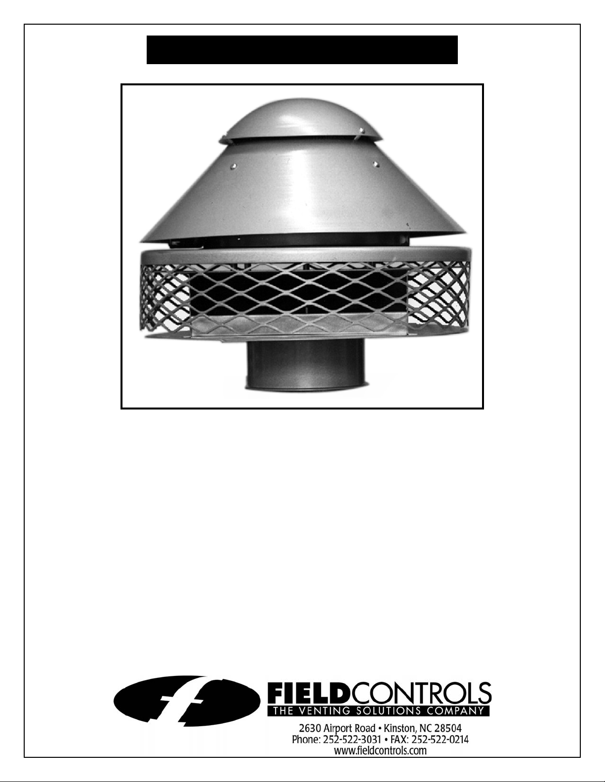
CHIMNEY TOP DRAFT INDUCER
Model: Type “C”
The Type “C” Chimney Top Draft Inducer is designed for installation on smoke
pipes, Type” B” vents, Type “L” vents and factory built Class “A” chimneys. The
Type “C” Draft Inducer is installed on the top of the vent system outside of the
building.
English .......Page 1
Français .....Page 4
Espanõl ......Page 6
Page 2

INSTALLATION
MOKE PIPE, TYPE “B” VENTS AND TYPE ”L” VENTS
S
1. Insert the Type “C” housing directly into the vent pipe. (See Figure 1)
2. Fasten housing to vent pipe using three (3) sheet metal screws, located 120º
apart.
3. Seal joint with a high temperature silicone adhesive sealant
M
ASONRY CHIMNEYS
1. Measure the size of the chimney liner and compare this dimension to the
diameter of the base plate on the inducer. Allow for at least ½ inch overlap of
the base plate. If this overlap cannot be maintained, refer to Installation with
Chimney Cap Section.
2. Apply a bead of high temperature silicone adhesive sealant around the
edge of the masonry top or chimney liner.
3. Install the draft inducer on top of the chimney with the unit resting on the
base plate. Make sure the unit is sealed. Fasten the inducer to the chimney
using anchor bolts and securing wires or cables. (See Figure 2)
W
ITH CHIMNEY CAP
1. Construct a chimney cap that completely covers the outside of the chimney.
(See Figure 3)
Figure 1
2. Apply a bead of high temperature silicone adhesive sealant around the hole
cut in the center of chimney cap. Fasten chimney cap onto draft inducer
base plate with three (3) sheet metal screws.
3. Apply a bead of high temperature silicone adhesive sealant around edge of
the masonry top and fasten chimney cap onto chimney. (See Figure 4)
Figure 2
Figure 3
Figure 4
Page 2
Page 3
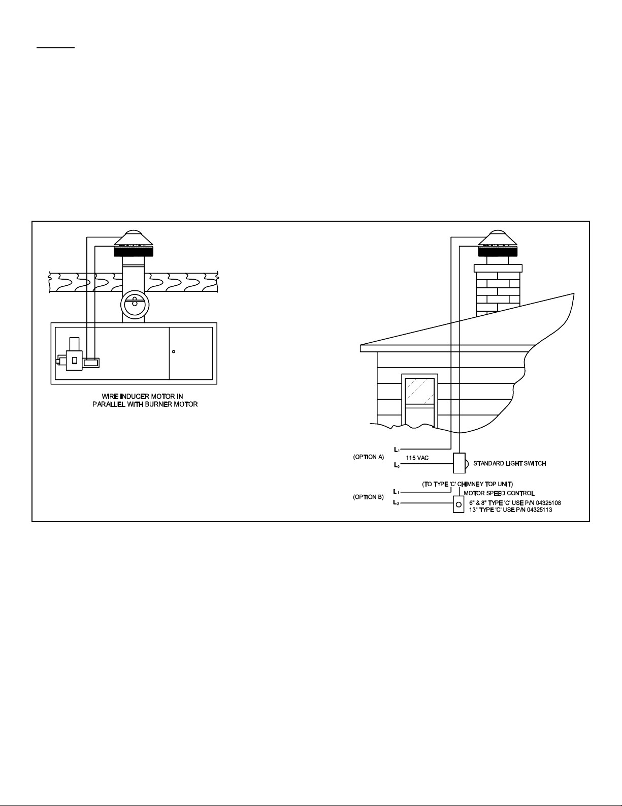
WIRING
1. Remove the four (4) screws that hold the conical rain cover in place.This will expose the motor juction box.
CAUTION: Disconnect electrical power when wiring dr aft inducer.
2. Wire the draft inducer in accordance with the National Electrical Code and applicable local codes. UNIT MUST BE
GROUNDED! Check ground circuit to make certain the unit has been properly grounded. The wiring should be
protected by an overcurrent protection circuit, such as a fuse or circuit breaker rated at 15 amperes. (See Diagram A)
3. After wiring, replace conical rain cover.
Diagram A
Page 3
Page 4

INDUCTEUR DE TIRAGE DE TETE DE CHEMINEE
Model: Type “C”
INSTALLATION
T
UYAUX DE CHEMINÉE, ÉVENTS DE TYPE"B" ET ÉVENTS DE TYPE "L"
1. Insérer le boîtier de type "C" directement dans le tuyau de ventilation. (Voir
Le Schéma 1)
2. Fixer le boîtier au tuyau de ventilation au moyen de trois vis à tôle, à 120° de
distance.
3. Sceller le joint au moyen d’un adhésif de silicone à haute température.
C
HEMINÉES DE MAÇONNERIE
1. Mesurer la doublure de cheminée et comparer ses dimensions au diamètre
de la plaque de base de l’inducteur. Prévoir un chevauchement d’au moins
½ po sur la plaque de base. Si ce chevauchement est impossible, se reporter à
la section Installation avec chapiteau de cheminée.
2. Appliquer un cordon d’adhésif de silicone à haute température au bord de la
cheminée de maçonnerie, dans le haut, ou au bord de la doublure de cheminée.
3. Installer l’inducteur de tirage dans le haut de la cheminée, en s’assurant que
l’unité repose bien contre la plaque de base. S’assurer que l’unité est scellée.
Fixer l’inducteur à la cheminée au moyen de boulons d’ancrage et de fils ou de
câbles de fixation. (Voir Le Schéma 2)
Schéma 1
A
VEC CHAPITEAU DE CHEMINÉE
1. Construire un chapiteau de cheminée qui couvre entièrement l’extérieur de la
cheminée. (Voir Le Schéma 3)
2. Appliquer un cordon d’adhésif de silicone à haute température autour du trou
coupé au centre du chapiteau de cheminée. Fixer le chapiteau à la plaque de
base de l’inducteur de tirage au moyen de trois vis à tôle.
3. Appliquer un cordon d’adhésif de silicone à haute température au bord
de la cheminée de maçonnerie, dans le haut, et fixer le chapiteau à la
cheminée. (Voir Le Schéma 4)
Schéma 2
Schéma 3
Page 4
Schéma 4
Page 5

CÂBLAGE
1. Retirer les quatre vis qui maintiennent le capuchon conique en place, de façon à exposer la boîte de jonction du
moteur.
ATTENTION: Couper l’alimentation électrique avant de câbler l’inducteur de tirage.
2. Câbler l’inducteur de tirage selon le Code national de l’électricité et les codes locaux applicables. L’UNITÉ DOIT
ÊTRE MISE À LA TERRE ! Vérifier le circuit de terre pour s’assurer que l’unité a été mise à la terre de façon
appropriée. Le câblage devrait être protégé par un dispositif de protection de surintensité (fusible ou disjoncteur)
classé à 15 A. (Voir Les Diagramme A)
3. Après le câblage, remettre le capuchon conique en place.
Diagramme A
Page 5
Page 6

INDUCTOR DE DIRCULACIÓN PARA LA PARTE
SUPERIOR DE LA CHIMENEA
Modelo: Tipo “C”
INSTALACIÓN
C
ONDUCTOS DE HUMO, RESPIRADEROS TIPO “B” Y RESPIRADEROS TIPO “L”
1. Introduzca el bastidor tipo “C” directamente en el tubo de ventilación. (Ver
Figura 1)
2. Afiance la caja al tubo de ventilación usando tres (3) tornillos para hoja
metálica, colocados a 120° de distancia.
3. Selle la junta con un compuesto sellador de silicona para altas
temperaturas.
C
HIMENEAS DE MAMPOSTERÍA
1. Mida el tamaño del revestimiento de la chimenea y compare esta
dimensión con el diámetro de la plancha de base del inductor. Deje por lo
menos ½ pulgada de superposición con la plancha de base. Si no se puede
mantener esta superposición, consulte las instrucciones en la sección de
instalación con casquete de chimenea.
2. Aplique una gota de compuesto sellador de silicona para altas temperaturas
alrededor del borde de la parte superior de la mampostería o del revestimiento
de la chimenea.
Figura 1
3. Instale el inductor de circulación en la parte superior de la chimenea con la
unidad apoyada sobre la plancha de base. Asegúrese de que la unidad esté
herméticamente cerrada. Afiance el inductor a la chimenea usando los pernos de
ancla y los alambres o cables de fijación. (Ver Figura 2)
C
ASQUETE DE CHIMENEA
1. Construya un casquete de chimenea que cubra completamente el exterior de la
chimenea. (Ver Figura 3)
2. Aplique una gota de compuesto sellador de silicona para altas temperaturas
alrededor del orificio cortado en el centro del casquete de la chimenea. Afiance
el casquete de la chimenea a la plancha de base del inductor de circulación
con tres (3) tornillos para hoja metálica.
Figura 2
Figura 3
3. Aplique una gota de compuesto sellador de silicona para altas temperaturas
alrededor del borde de la parte superior de la mampostería y afiance el
casquete de la chimenea a la chimenea. (Ver Figura 4)
Page 6
Figura 4
Page 7

CABLEADO
A
1. Saque los cuatro (4) tornillos que sostienen el capuchón cónico en posición. Esto dejará expuesta la caja de
empalme del motor.
PRECAUCIÓN: Desconecte la corriente eléctrica cuando conecte los cables del inductor de circulación.
2. Cablee el inductor de circulación conforme al Código Eléctrico Nacional y todo código local correspondiente. LA
UNIDAD DEBE SER PUESTA A TIERRA. Inspeccione el circuito de puesta a tierra para asegurarse de que la
unidad se haya puesto a tierra correctamente. Los cables debe estar protegidos por medio de un circuito de
protección contra sobrecorriente, como un fusible o un disyuntor con clasificación nominal de 15 amperios. (Ver
diagramas A)
3. Después del cableado, vuelva a colocar el capuchón cónico.
Diagramas
Page 7
Page 8

OPTIONAL RAIN SHIELD INSTALLATION INSTRUCTIONS:
As an optional accessory to the Type C Draft Inducer, a rain shield has been provided to further prevent water from wind
driven rain from entering the chimney. To install please follow the instructions below.
1. Remove cap on Type C unit by removing the four mounting screws as shown in figure 1.
2. Apply a bead of the provided silicone sealant along the edges of the first three sections. (See Figure 2)
3. Then using the provided #8x3/8 screws, join the three sections by screwing each section together at the first 3 holes.
(See Figure 3)
4. Apply a bead of silicone sealant around the top of the unit at the approximate position shown in Figure 4.
5. Center the assemble three sections of the rain shield over the Type C unit so that the opening allows for the electrical
box as shown in Figure 5.
6. Apply two strips of silicone sealant the the edges of the assembled section to seal the fourth section. (See Figure 6)
7. Insert fourth section under electrical box and on top of the assembled three sections. Using the remaining #8x3/8
screws, complete the four piece assembly. (See Figure 7)
8. Using the #10x5/8 self drilling screws provided, mount the shield to the Type C unit using the two holes at the top of
each section. (See Figure 8)
9. Re-attach the cap of the Type C unit. (See Figure 9)
Figure 1
Figure 4
Figure 7
Figure 2
Figure 5
Figure 8
Figure 3
Figure 6
Figure 9
Page 8
PN 04052900 Rev C 10/06
 Loading...