

Page 1
THERMAL SAFETY SWITCH
I
:
Model: TSP-1
Installation of a Thermal Safety Switch or Spillage Switch is
recommended for L.P. and Natural Gas fired systems with draft hoods.
This device is installed to detect flue gas spillage from a blocked flue
system and/or inadequate draft. This device MUST be installed by a
qualified installer in accordance with manufacturer’s installation
instructions. Wiring should be in accordance with the manufacturer’s
recommendations, National Electrical Code and applicable local codes.
NOTE: For 30 Millivolt Wiring Applications, the TCA-1 Thermocouple
Adapter must be ordered sparately. (Part No. 46082700)
TEMS SUPPLIED WITH KIT
1 Thermal Safety Switch Assembly
3 Probe Mounting Tabs
5 #8 Self-tapping Sheet Metal Screws
Page 2
INSTALLATION
CAUTION: Never attempt to shorten probe length. Avoid kinking
probe while handling. Before and after installation, it is
recommended to follow the pre-installation inspection
instructions.
NOTE: Probe length is designed for mounting on draft hoods up
to 6” Dia. Pipe size. To achieve 360° spillage sensing on larger
draft hood, an additional switch or switches would be required.
WATER HEATERS AND BOILERS
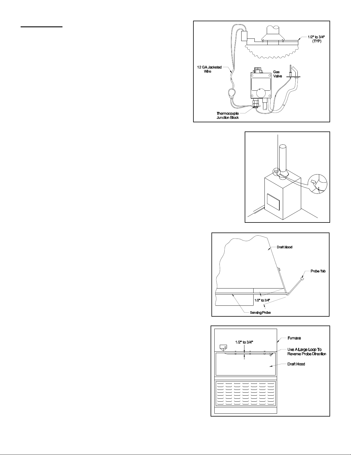
1. Mount the switch box onto the appliance 2 to 3 inches away
from the draft hood using two sheet metal screws. The probe
should be directed towards the draft hood. (See Figure 1)
An alternative mounting method is to mount the switch
directly onto the draft hood. (See Figure 2)
2. Mount the probe tabs around the draft hood, located
approximately 120° apart. The bottom of the bent end should be ½ to ¾ inches
away from the bottom edge of the draft hood. (See Figure 3)
3. Carefully uncoil and route the probe around the draft hood. (See Figure 3) Avoid
bending the sensing probe, kinks can alter the switches performance. NOTE: For
small draft hoods, multiple wraps around the draft hood is required.
4. To secure the probe, bend the tab ends to hold the probe secure.
FURNACES OR UNIT HEATERS
1. Mount the switch on the outside of the appliance near the draft hood. The probe
should be directed towards the draft hood.
2. Mount the probe tabs along the top edge of the draft hood. (See Figure 4) The
bottom of the bent end should be ½ to ¾ inches away from the edge of the draft
hood.
3. Carefully uncoil and route the probe along the draft hood. (See
Figure 4) Avoid bending the sensing probe, kinks can alter the
switches performance. NOTE: For small draft hoods, double back
with the probe using a minimum of a 1 inch radius to bend the
probe. (See Figure 4)
4. To secure the probe, bend the tab ends to hold the probe secure.
Figure 1
Figure 2
Figure 3
Figure 4
Page 2
Page 3

WIRING
Figure 5
Diagram A
Refer to System Check-out Procedure Section before operating.
24 VAC SYSTEMS
CAUTION: Disconnect electrical power when wiring Safety Switch.
1. Remove one of the thermostat wires from the gas control valve and wire the safety switch in series with the
thermostat circuit. (See Diagram A)
2. After installing the safety switch, check the amperage drown through the thermostat circuit and adjust the thermostat
anticipator accordingly.
MILLIVOLT WIRING SYSTEMS
CAUTION: Shut off main gas supply to appliance before wiring.
NOTE: TCA-1 Thermocouple Adapter (Part No. 460827000)
required.
30 MILLIVOLT SYSTEM
1. Remove thermocouple from gas control valve. (See Figure 5)
2. Thread TCA-1 thermocouple adapter into thermocouple port,
then thread the thermocouple into the bottom of the TCA-1.
(See Figure 6)
3. Connect lead wires (NOTE: 12 GA wire should be used) from the TCA-1
thermocouple adapter to the leads on the thermal switch. (See Diagram B)
750 MILLIVOLT SYSTEM
Wire the TSP-1 thermal switch in series with one side of the thermostat circuit (See
Diagram C) or pilot generator circuit.
SYSTEM CHECK-OUT PROCEDURE
1. Push the reset on the spillage switch. Light the appliance burner in accordance
with manufacturer’s instructions. Operate the appliance to determine that the
appliance will operate continuously.
2. Adjust thermostat so the appliance burner is shut off. Allow system to
cool down, then remove the vent pipe connection near the appliance.
3. Block the appliance vent outlet with a noncombustible material.
4. Adjust thermostat control to call for heat. Allow approximately 2 minutes
for the system flue gases to back up and the gas burner to shut off.
5. Push the reset on the spillage switches, then relight appliance and
perform Steps 3 & 4 again.
Figure 6
Diagram B
6. Re-connect vent pipe connection and cycle system 2 to 3 times to ensure
continuous operation.
NOTE: Shutdown of appliance burner should not be more than 10 minutes.
Diagram C
PRE-INSTALLATION INSPECTION INSTRUCTIONS FOR EXISTING APPLIANCES
RECOMMENDED PROCEDURE FOR SAFETY INSPECTION OF AN EXISTING APPLIANCE INSTALLATION BY THE NATIONAL FUEL GAS
CODE 54, Z223.1 APPENDIX H:
The following procedure is intended as a guide to aid in determining that an appliance is properly installed and is in a safe
condition for continuing use. This procedure is predicated, on central furnace and boiler installations, and it should be
Page 3
Page 4

recognized that generalized procedures cannot anticipate all situations. Accordingly, in some cases deviation from this
procedure may be necessary to determine safe operation of the equipment:
a. This procedure should be performed prior to any attempt to modification of the appliance or of the installation.
b. If it is determined there is a condition which could result in unsafe operation, the appliance should be shut off and
the owner advised of the unsafe condition.
THE FOLLOWING STEPS SHOULD BE FOLLOWED IN MAKING THE SAFETY INSPECTION:
1. Conduct a gas leakage test of the appliance piping and control system downstream of the shut off valve in the supply
line to the appliance.
2. Visually inspect the venting system for proper size and determine there is no blockage or restriction, leakage,
corrosion, and other deficiencies which could cause an unsafe condition.
3. Shut off all gas to the appliance and shut off any other fuel-gas burning appliance within the same room. Use the shut
off valve in the supply line to each appliance.
4. Inspect burners and crossovers for blockage and corrosion.
5. Applicable only to furnaces. Inspect heat exchanger for cracks, openings, or excessive corrosion.
6. Applicable only to boilers. Inspect for evidence of water or combustion product leaks.
7. Insofar as practical, close all building doors and windows and all doors between the space in which the appliance is
located and other spaces of the building. Turn on clothes dryers. Turn on any exhaust fans, such as range hoods and
bathroom exhausts, so they will operate at maximum speed. Do not operate a summer exhaust fan. Close fireplace
dampers. If, after completing Steps 8 through 13, it is believed sufficient combustion air is not available, refer to local
codes, or in the absence of local codes, to the National Fuel Gas Code, A.N.S.I. Z223.1 No. 54 for guidance.
8. Place in operation the appliance being inspected. Follow the lighting instructions. Adjust thermostat so appliance will
operate continuously.
9. Determine that the pilot(s) is burning properly and that main burner ignition is satisfactory by interrupting and
reestablishing the electrical supply to the appliance in any convenient manner. Test the pilot safety device to
determine it is operating properly by extinguishing the pilot burner(s) when the main burner(s) is off and determine,
after 3 minutes, that the main burner gas does not flow upon a call for heat.
a. Visually determine that main burner gas is burning properly: i.e., no floating, lifting, or flashback. Adjust the
primary air shutter(s) as required.
b. If appliance is equipped with high and low flame controlling or flame modulation, check for proper main burner
operation at low flame.
10. Test for spillage at draft hood relief opening after 5 minutes of main burner operation. Use a draft gauge, flame or a
match or candle, or smoke from a cigarette, cigar, or pipe.
11. Turn on all other fuel-gas burning appliances within the same room so they will operate at their full inputs. Follow
lighting instructions for each appliance.
12. Repeat Steps 10 through 12 on the appliance being inspected.
13. Return doors, windows, exhaust fans, fireplace dampers, and any other fuel-gas burning appliance to their previous
conditions of use.
14. Applicable only to furnaces. Check both the limit control and fan control for proper operation. Limit control operation
can be checked by blocking the circulation air inlet or temporarily disconnecting the electrical supply to the blower
motor and determine that the limit control acts to shut off the main burner gas.
15. Applicable only to boilers.
a. Determine that the water pumps are in operating condition.
b. Test low water cutoffs, automatic feed controls, pressure and temperature limit controls, and relief valves in
accordance with the manufacturer’s recommendations to determine they are in operating condition.
Page 4
PN 46170300 Rev A 11/00
 Loading...