

Page 1

REPAIR MOTOR KIT
Model: SWG-4HD, SWGII-4HD, SWG-5,
SWGII-5, SWG-6, SWGII-6
This kit includes a replacement assembly for the SWG and SWGII series sidewall power
venter models listed above.
NOTE: Before working on power venter, shut o electrical power to control box.
ITEMS INCLUDED:
1- Replacement Motor and Blower Wheel on Mounting Bracket with Mounting Fasteners
1
1-
⁄8" Hex wrench
1- Tube of high temperature silicone sealant
1- Instruction Sheet
READ THESE INSTRUCTIONS CAREFULLY AND COMPLETELY BEFORE PROCEEDING WITH THE INSTALLATION.
This device MUST be installed by a quali ed agency in accordance with the manufacturer's installation instructions. The de nition of
a quali ed agency is: any individual, rm, corporation or company which either in person or through a representative is engaged
in, and is responsible for, the installation and operation of HVAC appliances, who is experienced in such work, familiar with all the
precautions required, and has complied with all the requirements of the authority having jurisdiction.
Please retain these instructions after installation.
Installed By: Phone:
Installation Date:
www. eldcontrols.com
Page 2
IDENTIFY WHICH MODEL POWER VENTER YOU HAVE
CAUTION: Avoid applying excess pressure on the blower wheel when handling. This will cause an imbalance
of the blower wheel which will result in excessive vibration and premature motor failure.
REMOVAL
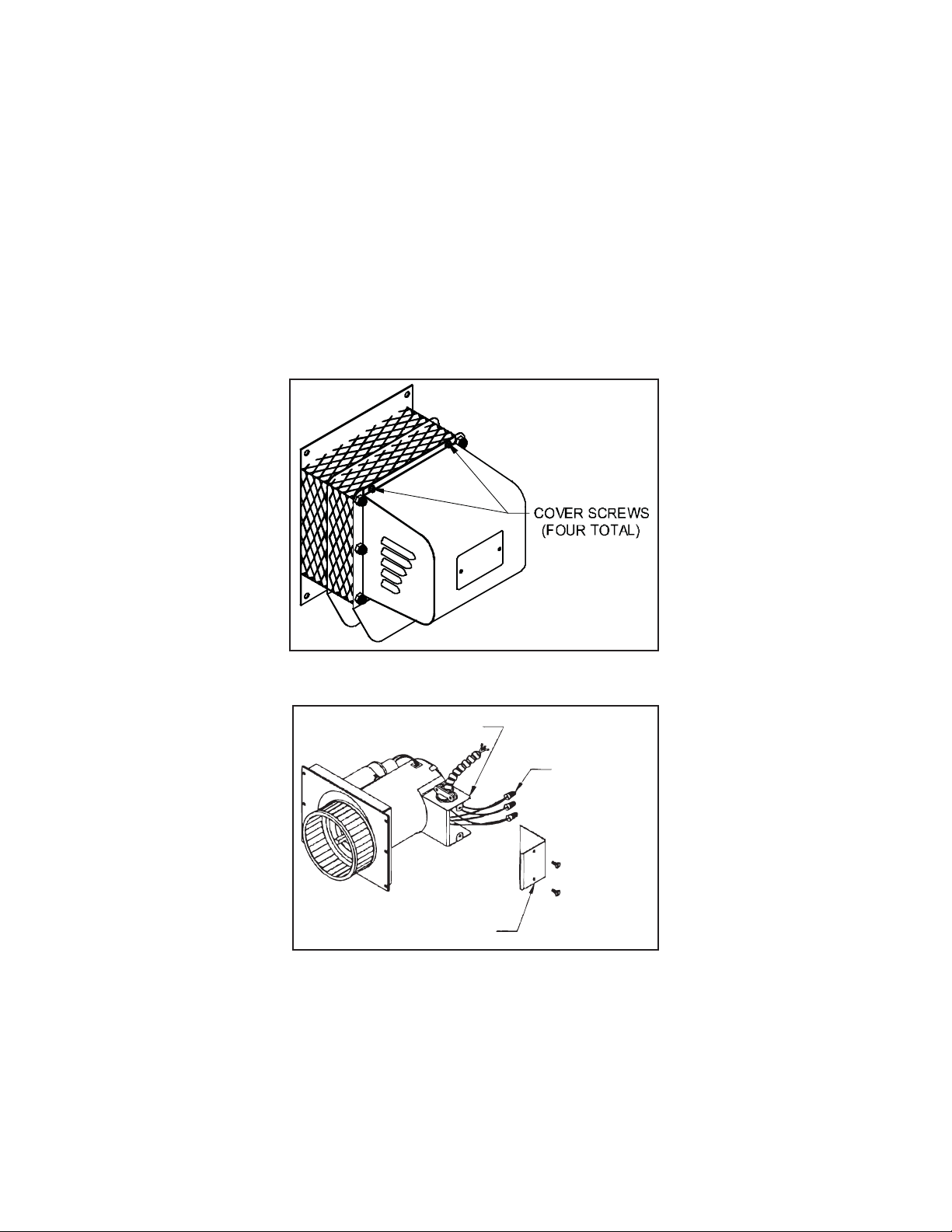
1. Remove motor cover. (See Figure 1)
2. Remove the electrical box cover and disconnect the conduit and wires. (See Figure 2) It is not necessary
to disconnect the wires from the Control Kit.
3. Remove the nuts securing the motor assembly, and pull the motor assembly straight o of the unit.
(See Figure 3)
4. Clean o any build-up inside the blower wheel housing.
ELECTRICAL BOX
ELECTRICAL BOX COVER
Figure 1
WIRE NUTS
Figure 2
page 2
Page 3

INSTALLATION
1. Align the holes in the circular cover plate with the holes in the motor mount bracket on the motor
assembly. (See Figure 3)
2. Slide the motor assembly onto the protruding threaded studs on the power venter body with the exhaust
chute pointing downward, and replace the nuts securely to the threaded studs. (See Figure 3)
3. Use the top knockout on the electrical box and reattach the exible conduit and wires to the motor using
the conduit connector and wire nuts. Secure the cover on the electrical box.
4. Seal around the edge of the motor mount bracket with the provided high temperature silicone sealant.
Install the motor cover with the side louvers pointing downward. (See Figure 1)
Figure 3
MAINTENANCE
1. Motor: Inspect the motor once a year - motor should rotate freely. To prolong the life of the motor, it must be
lubricated with six drops of SWG Superlube, Part # 46226200, annually. NOTE: Some models may have sealedbearing motors, which do not require lubrication.
2. Wheel: Inspect the power venter wheel annually to clear any soot, ash or coating which inhibits either rotation
or air ow. Remove all foreign materials before operating.
3. Vent System: Inspect all vent connections annually for looseness, for evidence of corrosion and for ue gas
leakage. Replace, seal or tighten pipe connections if necessary. Check the power venter choke plate to ensure
it is secured in place. Check the barometric draft control, if installed, to ensure the gate
swings freely.
4. System Safety Devices: With the heating system operating, disconnect the pressure sensing tube from
the pressure switch on the CK Kit. This will stop the burner operation. Re-connecting the tube will relight
the burner. For 30 millivolt operating systems, disconnect one lead of the spill switch circuit from the
thermocouple junction block. This will shut o the pilot and the burner. Re-connection will allow relighting
the pilot.
page 3
Page 4

LIMITED WARRANTY
Field Controls, LLC (“Company”) warrants that its products shall be free from defects in material and workmanship
under normal use for the limited period indicated, from the date of manufacture, subject to the provisions 1-8 below.
Eighteen (18) months
All Field Controls Products (except for those listed below as 5 years or 90 days).
Five (5) years
Field Controls Direct Vent Systems (FDVS), Field Oil Vent Kits (FOVP), and ComboVents (CV).
Field Controls warrants that the products listed below shall be free from defects in material and workmanship under
normal use for the limited period indicated, from the date of purchase by the consumer, subject to the provisions
1-8 below.
Ninety (90) days
UV lamps/bulbs
Provisions:
1. During the limited warranty period, Company, or its authorized service representative, will repair or replace, at Company’s
option, without charge, a defective Product. Product that is repaired may be repaired with new or refurbished replacement
parts. Product that is replaced may be replaced with a new or refurbished product of the same or similar design. Company
will return repaired or replacement Product to customer in working condition. Labor charges are not covered as part of the
limited warranty.
2. With regard to UV lamps/bulbs, customer shall be required to include a "valid proof of purchase" (sales receipt) identifying
the Product purchased (Product model or accurate date code information) and the date the Product(s) was purchased.
3. Product whose warranty/quality stickers, Product serial number plates or electronic serial numbers have been removed,
altered or rendered illegible shall not be covered under the limited warranty.
4. Defective Product must be returned to Company, postage prepaid.
5. IN NO EVENT SHALL COMPANY BE LIABLE FOR ANY INDIRECT, SPECIAL, INCIDENTAL, CONSEQUENTIAL, OR SIMILAR
DAMAGES (INCLUDING, BUT NOT LIMITED TO, LOST PROFITS OR REVENUE, INABILITY TO USE PRODUCT, OR OTHER
ASSOCIATED EQUIPMENT, THE COST OF SUBSTITUTE EQUIPMENT, AND CLAIMS BY THIRD PARTIES) RESULTING FROM
THE USE OF PRODUCT. Some states do not allow the exclusion or limitation of incidental or consequential damages, so the
above limitation or exclusion may not apply to you.
6. THIS WARRANTY AND REMEDIES ARE EXCLUSIVE AND IN LIEU OF ALL OTHER WARRANTIES, REMEDIES AND
CONDITIONS, WHETHER ORAL, WRITTEN, EXPRESS, STATUTORY OR IMPLIED. TO THE EXTENT PERMITTED BY LAW,
COMPANY DISCLAIMS ALL IMPLIED AND STATUTORY WARRANTIES, INCLUDING WARRANTIES OF MERCHANTABILITY
AND FITNESS FOR A PARTICULAR PURPOSE.
7. Company makes no warranty of any kind in regard to other manufacturer’s products distributed by Company. Company will
pass on all warranties made by the manufacturer and where possible, will expedite the claim on behalf of the customer, but
ultimately, responsibility for disposition of the warranty claim lies with the manufacturer.
8. Product that has been subjected to misuse, accident, shipping or other physical damage, improper installation or application,
abnormal operation or handling, neglect, fire, water or other liquid intrusion are not covered by the warranty.
Phone: 252.522.3031 • Fax: 252.522.0214
www.fieldcontrols.com
© Field Controls, LLC P/N 46252300 Rev H 10/12
 Loading...