

Page 1
REPAIR MOTOR KIT
Model: SWG-4HD, SWGII-4HD, SWG-5
SWGII-5, SWG-6, SWGII-6
BEFORE WORKING ON POWER VENTER,
SHUT OFF ELECTRICAL POWER TO CONTROL BOX
This kit includes a replacement motor assembly for the SWG and SWGII series sidewall power venter
models listed above.
ITEMS INCLUDED:
Replacement Motor and Blower Wheel on Mounting Bracket
Adapter Plate (for SWG Models)
Mounting Fasteners
Blower Wheel Depth Gage
1/8" Hex wrench
Tube of high temperature silicone sealant
Instruction Sheet
Page 2
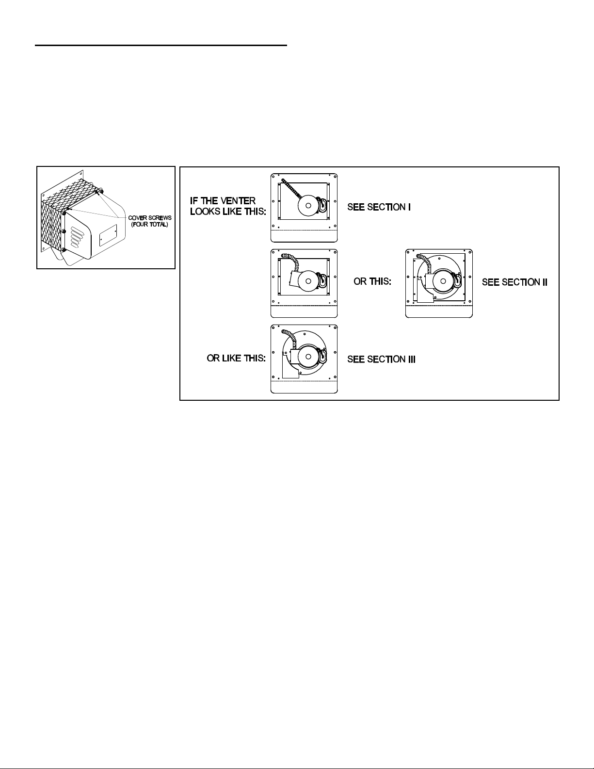
IDENTIFY WHICH MODEL POWER VENTER YOU HAVE
Figure 2
CAUTION: Avoid applying excess pressure on the blower wheel when handling. This will cause an imbalance of the
blower wheel which will result in excessive vibration and premature motor failure.
1. Remove motor cover. (See Figure 1)
2. Verify which power venter you have to determine which section to reference. (See Figure 2)
3. Refer to one of the following sections for removal and installation of the replacement motor kit.
4. This kit is pre-assembled for the SWGII series power venter but includes an adapter plate for mounting to an SWG
series venter.
Figure 1
Page 2
Page 3
SECTION I (Models SWG-4HD, SWG-5, SWG-6)
6
REMOVAL
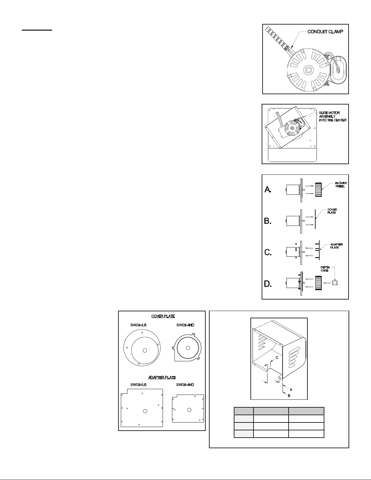
1. Remove the clamps from the conduit and motor and disconnect the motor lead
wires from the Control Kit. (See Figure 3) Attach a "pull" or "fish" wire to the motor
lead wires on the Control Kit side to use to pull the leads from the new repair kit
motor through the conduit during re-assembly.
2. Remove the screws securing the motor assembly. Rotate the motor assembly
counterclockwise and slide the assembly into the center, then pull the motor
assembly out of the unit. (See Figure 4)
3. Clean off any build-up inside the blower wheel housing.
INSTALLATION
This kit is pre-assembled for the SWGII series power venter, therefore the following
must be done to adapt the kit to an SWG series venter.
1. Remove the blower wheel from the Repair Motor Kit using the provided 1/8” hex
wrench. (See Figure 5A)
2. Remove the flat circular cover plate and replace with the provided adapter plate as
shown in Figure 5B and 5C (Refer to Figure 6 for identifying the cover plate and
adapter plate.) Use an 11/32” nut driver to tighten the provided nuts onto the studs
on the adapter plate.
3. Re-attach the blower wheel, setting the depth on the motor shaft using the "2" side
of the provided "H"-shaped depth gage. (See Figure 5D) The "1" side of the depth
gage is for setting the blower wheel on the shaft when not using the adapter plate.
Figure 3
Figure 4
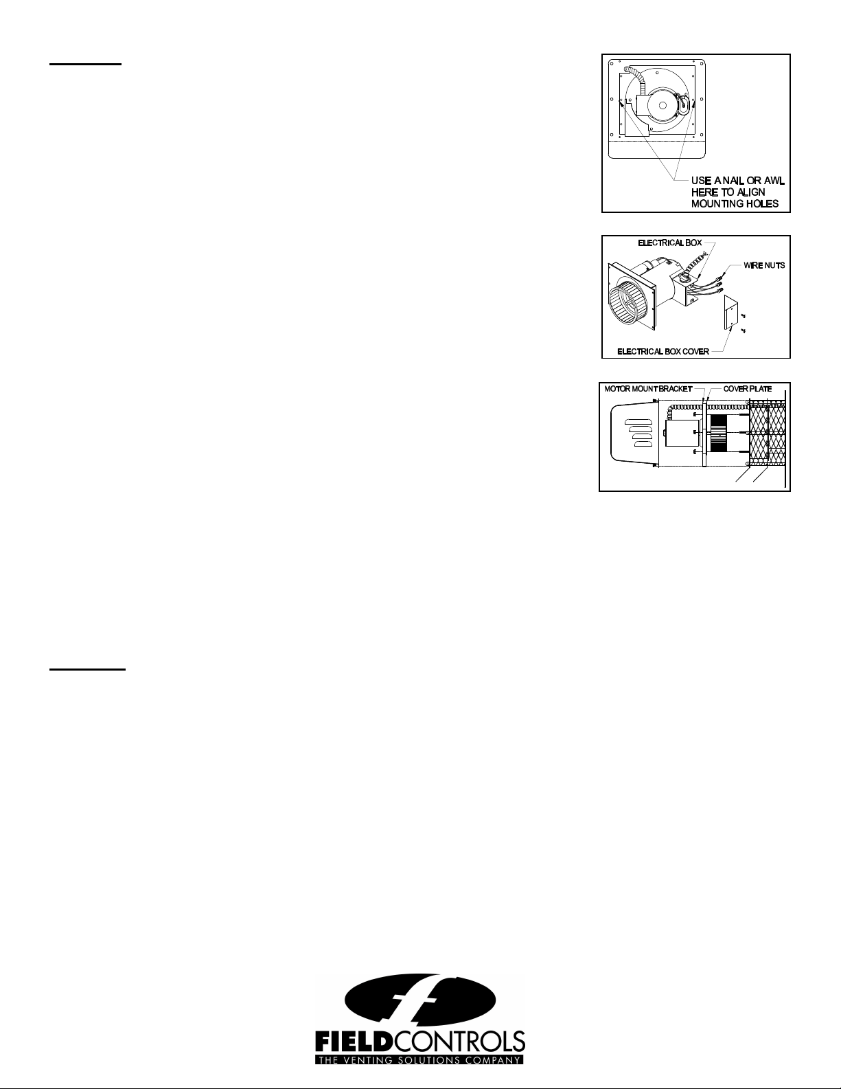
4. Insert the blower wheel into the hole in the front plate of the venter housing.
5. Locate the motor assembly into position and rotate as shown in Figure 4. Slide the
assembly over the mounting holes in the front plate. It may be necessary to use
two nails or awls to hold the assembly in position. (See Figure 8) Use provided
sheet metal screws to secure motor assembly into position at the four corners,
then secure center two holes.
6. Route the wires from the new motor repair kit through the conduit and attach to the
Control Kit in the appropriate location. Use the top knockout on the electrical box
and attach the flexible conduit and wires to the motor using the provided conduit
connector and wire nuts. Secure the cover on the electrical box.
7. Seal around the edge of the circular motor mount bracket and the top of the
rectangular adapter bracket with the provided high temperature silicone sealant.
8. Cut a notch in the bottom of
the motor cover using sheet
metal shears as shown in
Figure 7. This must be done
to provide clearance for the
exhaust chute of the new
motor assembly. Re-install
the motor cover with the side
louvers pointing downward
as shown in Figure 1.
Figure 5
DIM. SWG-4HD SWG-5,6
Figure
A
B
C
3/4” 1”
3-1/4” 3-3/4”
3/4” 3/4”
Figure 7
Page 3
Page 4
SECTION II (Models SWG-4HD, SWG-5, SWG-6)
Figure 10
P/N 46252300 Rev E 01/01
REMOVAL
1. Remove the electrical box cover from the motor and disconnect the conduit and
wires. (See Figure 9) It is not necessary to disconnect the wires from the Control Kit.
2. Remove the screws securing the motor assembly. Rotate the motor assembly
counterclockwise and slide the assembly into the center, then pull the motor
assembly out of the unit. (See Figure 4)
3. Clean off any build-up inside the blower wheel housing.
INSTALLATION
1. Remove the blower wheel from the Repair Motor Kit using the provided 1/8” hex
wrench. (See Figure 5A)
2. Remove the flat circular cover plate and replace with the provided adapter plate as
shown in Figure 5B and 5C. (Refer to Figure 6 for identifying the cover plate and
adapter plate.) Use an 11/32” nut driver to tighten the provided nuts onto the studs
on the adapter plate.
Figure 8
3. Re-attach the blower wheel, setting the depth on the motor shaft using the "2" side
of the provided "H"-shaped depth gage. (See Figure 5D) The "1" side of the depth
Figure 9
gage is for setting the blower wheel on the shaft when not using the adapter plate.
4. Insert the blower wheel into the hole in the front plate of the venter housing.
5. Locate the motor assembly into position and rotate as shown in Figure 4. Slide the
assembly over the mounting holes in the front plate. It may be necessary to use
two nails or awls to hold the assembly in position. (See Figure 8) Use provided
sheet metal screws to secure motor assembly into position at the four corners,
then secure center two holes.
6. Use the top knockout on the electrical box and re-attach the flexible conduit and
wires to the motor using the provided conduit connector and wire nuts. Secure the cover on the electrical box.
7. Seal the around the edge of the circular motor mount bracket and top of the rectangular adapter bracket (if applicable)
with the provided high temperature silicone sealant.
8. Cut a notch in the bottom of the motor cover using sheet metal shears as shown in Figure 7. This must be done to
provide clearance for the exhaust chute of the new motor assembly. Re-install the motor cover with the side louvers
pointing downward as shown in Figure 1.
SECTION III (Models SWGII-4HD, SWGII-5, SWGII-6)
REMOVAL
1. Remove the electrical box cover and disconnect the conduit and wires. (See Figure 9) It is not necessary to
disconnect the wires from the Control Kit.
2. Remove the nuts securing the motor assembly, and pull the motor assembly straight off of the unit. (See Figure 10)
3. Clean off any build-up inside the blower wheel housing.
INSTALLATION
1. Align the holes in the circular cover plate with the holes in the motor mount bracket on the motor assembly. (See
Figure 10)
2. Slide the motor assembly onto the protruding threaded studs on the power venter body with the exhaust chute
pointing downward, and replace the nuts securely to the threaded studs. (See Figure 10)
3. Use the top knockout on the electrical box and reattach the flexible conduit and wires to the motor using the conduit
connector and wire nuts. Secure the cover on the electrical box.
4. Seal around the edge of the motor mount bracket with the provided high temperature silicone sealant. Install the
motor cover with the side louvers pointing downward as shown in Figure 1.
Page 4
 Loading...