

Page 1
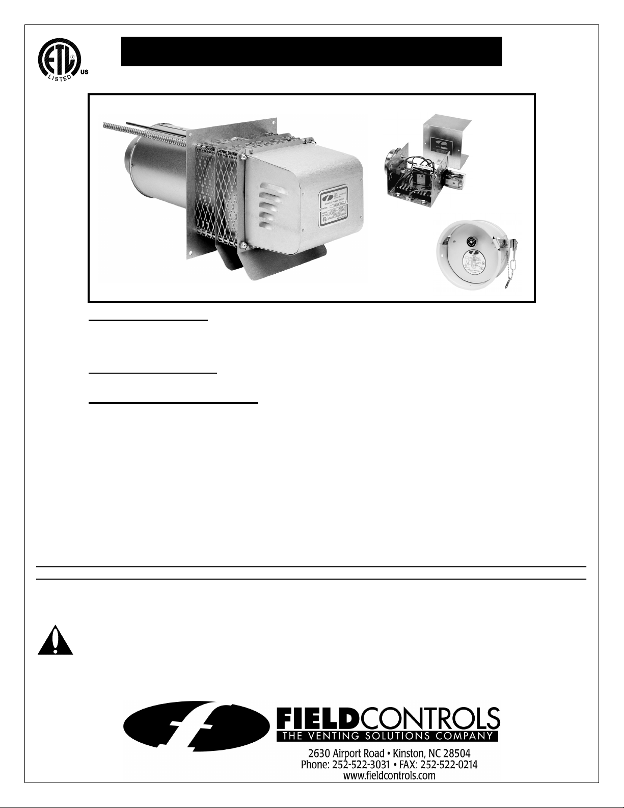
SIDEWALL POWER VENTING SYSTEM
Model: SWG-4G
ITEMS INCLUDED IN KIT
1 - SWGII-4HD Sidewall Power Venter
1 - CK-43F Control Kit (includes 4" MG-1 Barometric Draft Control)
1 - Installation Instructions
OPTIONAL COMPONENTS
PEK-4HD Extension Kit. For installations in walls over 8" thick.
GENERAL SYSTEM INFORMATION
Designed for operation with natural gas and LP gas.
1. The thermostat calls for heat and energizes a relay which activates the power venter. After
the venter motor has come up to speed, the pressure switch closes. This closes the circuit
to the burner and allows the burner to fire.
2. After the heating requirement has been satisfied, the thermostat circuit will open and deactivate the burner.
3. The power venter operates for a period of time after the burner has shut off to purge
remaining flue gases.
WARNING: Bodily injury can result from high voltage electrical components, fast moving fans, and combustible
gas. For protection from these inherent hazards during installation and servicing, the electrical supply must be
disconnected and the main gas valve must be turned off. If operating checks must be performed with the unit
operating, it is the technicians responsibility to recognize these hazards and proceed safely.
DO NOT DESTROY
THESE INSTRUCTIONS MUST REMAIN WITH EQUIPMENT
Page 2
INSTALLATION SAFETY INSTRUCTIONS
CAUTION: The power venting system must be installed by a qualified installer. "Qualified Installer" means an individual
who has been properly trained or a licensed installer. The installer must write or imprint his name, phone number, and
date of installation on the installation tag. The tag should be attached to the power venting system control kit box or power
venter unit.
1. Safety inspection of a venting system should be performed before and after installing a power venting system on an
existing or new appliance. Procedures to follow are those recommended by the National Fuel Gas Code, ANSI
Z223.1, CGA Standard B149.1-M91 or B149.2-M91, or refer to the General Installation Inspection section of this
manual.
2. Plan the vent system layout before installation to avoid the possibility of accidental contact with concealed wiring or
plumbing inside walls.
3. Single wall vent pipe (refer to Diagram B) may be used to join the appliance to the power venter. If proper clearances
cannot be maintained from combustible material, Type B vent pipe should be used. Refer to national or local codes for
guidelines.
4. Disconnect power supply before making wiring connections to prevent electrical shock and equipment damage.
5. This equipment is designed to overcome minor negative pressure conditions. To ensure extreme negative pressure
does not exist, follow the General Installation Inspection section of this manual.
6. Air flow adjustment MUST be made to ensure appliance efficiency. This should be done at the appliance exhaust
outlet with a velocity meter or draft gauge.
7. On gas-fired furnaces, a barometric draft control must be installed to regulate proper air flow and fluctuations in the
system’s air flow during operation. Fluctuations may come from wind loads on the outlet of the power venter or house
depressurization during windy days.
8. The air pressure switch must be adjusted to assure safe operation. Failure to adjust the air pressure switch as
specified later in these instructions, could lead to improper operation of the venting system and furnace which will
result in product damage, personal injury, or death.
INSTALLATION OF SWG POWER VENTER
WARNING: Failure to install, maintain and/or operate the power venting system in accordance with the
manufacturer’s instructions may result in fire, personal injury, or death.
P
ROCEDURE FOR CALCULATING TOTAL EQUIVALENT PIPE LENGTH IN FEET
1. Calculate the total equivalent feet for each type of fitting used in the venting system from Table 1 below.
2. Calculate the total amount of feet for the straight lengths of vent pipe.
3. Add the equivalent feet for the fittings with the total amount of feet of straight lengths. This will approximate the total
equivalent feet of the vent system. The total equivalent feet must be less than the maximum equivalent vent length as
shown in OEM instructions.
Table 1
EQUIVALENT LENGTH (FEET) OF VENT PIPE FOR VENT PIPE FITTINGS
VENT PIPE FITTINGS 4” VENT PIPE DIAMETER
90° ELBOW 7
45° ELBOW 4
Example: System Pipe Size = 4"
Step 1 Two 4" 90° Elbows @ 7 feet each = 14 Ft.
Step 2 Ten 2 Foot Lengths of 4" Pipe = 20 Ft.
Step 3 Total Equivalent Feet = 14 Ft. + 20 Ft. = 34 Ft.
Page 2
Page 3
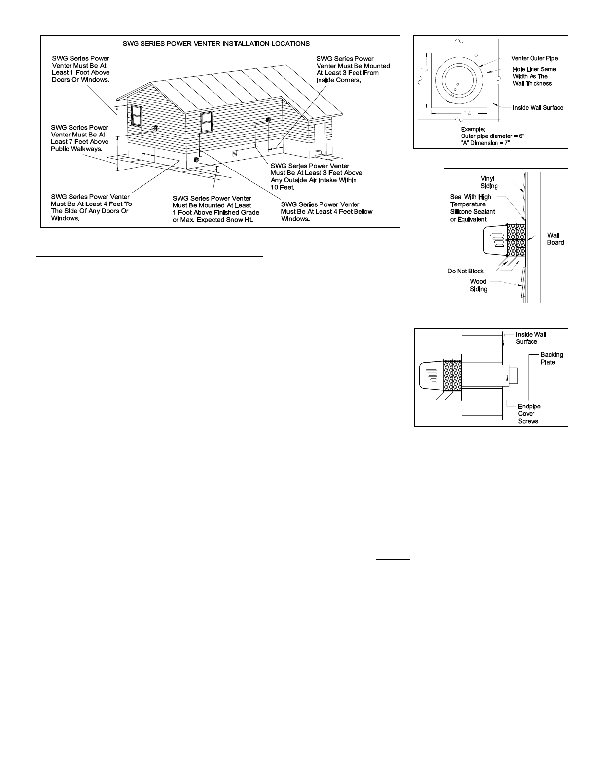
Figure 1
Diagram A
INSTALLATION FOR THE SWG POWER VENTER
1. Remove power venter from box and inspect unit for damage. If the carton has
been crushed or mutilated, check unit very carefully for damage. Rotate blower
wheel to insure that the motor and blower wheel rotate freely. DO NOT install if
any damage is apparent.
2. Location of the termination of the venting system should be installed in
Figure 2
accordance with the National Fuel Gas Code, ANSI Z223.1, CGA Standards
B149.1-M91, B149.2-M91, manufacturer's recommendations, and/or local
codes which are applicable. See requirements below or refer to installation
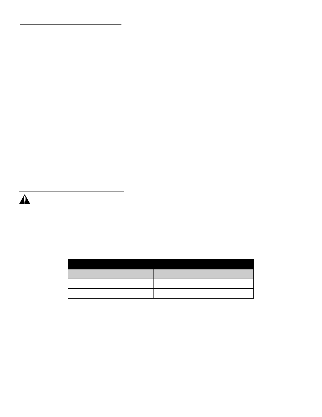
location Diagram A for typical locations.
a. The exit termination of mechanical draft systems shall not be less than 7'
above grade when located adjacent to public walkways.
b. A venting system shall terminate at least 3' above any forced air inlet lo-
cated within 10'. For Canadian applications, a venting system shall
terminate more than 6' away from a mechanical air supply inlet.
c. The venting system of other than a direct vent appliance shall terminate at
Figure 3
least 4' below, 4' horizontally from, or 1' above any door, window or gravity
air inlet into the building. For Canadian applications, according to CAN/CGA Standards B149.1-M91 and B149.2M91, 12" clearance is required for inputs up to and including 100,000 BTU/HR and 3' for inputs exceeding
100,000 BTU/HR.
d. The vent termination of a direct vent appliance with an input of 50,000 BTU's per hour or less, shall be located at
least 9" from any opening through which vented gases could enter the building. With an input over 50,000 BTU's
per hour, a 12" termination clearance shall be required.
e. The vent termination point shall not be installed closer than 3' from an inside corner of an L-shaped structure.
f. The vent termination should not be mounted directly above, or within 3' horizontally from an oil tank vent or gas
meter.
g. The bottom of the vent terminal shall be located at least 12" above finished
grade or maximum expected snow
height.
3. After determining the location of the venting system termination point (See Diagram A), cut a square hole through the
wall 1" larger than the outer pipe diameter of the power venter. (See Figure 1)
4. Seal the back side of the base plate around the outer pipe of the venter and the conduit with a bead of high
temperature silicone sealant. (See Figure 3) Mount the power venter through the wall, keeping the outer pipe centered
in the hole. (See Figure 1) Fasten the power venter to the outside wall with appropriate fasteners. Seal the edges of
the power venter base plate to the wall with a high temperature silicone sealant.
NOTE: If mounting the power venter through a combustible wall material and the flue gas temperature is above 400°F at
the power venter inlet, line the square hole with a piece of corrosion resistant sheet metal or non-combustible material.
The liner piece should be the same width as the wall section. (See Figure 1) The power venter has a maximum flue gas
temperature of 550°F at the venter inlet. For installation through walls over 8 inches thick, use an SWG Series Extension
Kit, Model PEK-4HD.
5. Remove the end pipe cover screws on the sides of the outside pipe and remove end pipe cover. Then mount the
backing plate over the outer pipe and route the flexible conduit and pressure switch tube through the holes provided in
the backing plate. Fasten the backing plate to the inside wall with appropriate fasteners. (See Figure 3) Re-install
cover and end pipe screws.
Page 3
Page 4
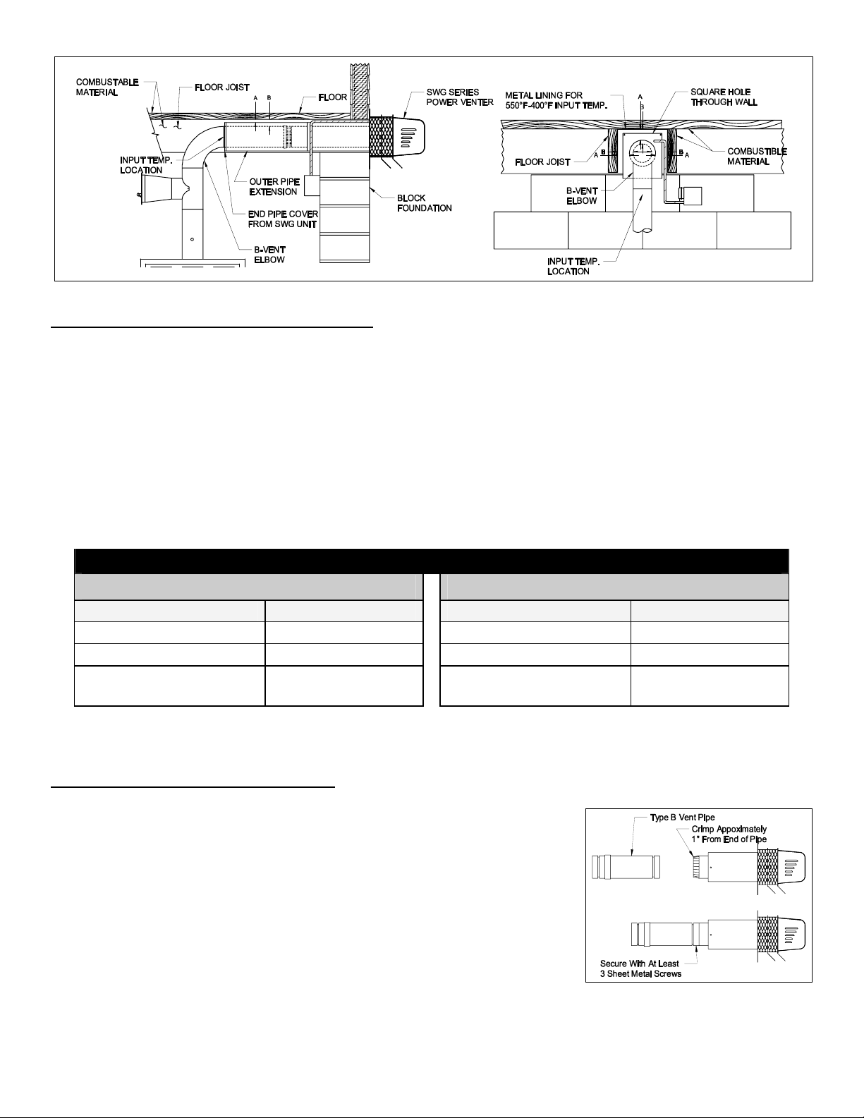
Diagram B
CONNECTING POWER VENTER TO APPLIANCE
The venting system should be installed and supported in accordance with the National Flue Gas Code, ANSI Z223.1,
CGA Standards B149.1-M91, B149.2-M91, or in accordance with any local codes. A vent pipe connector shall be
supported for the design and weight of the material employed, to maintain clearances, prevent physical damage and
separation of joints.
If mounting venting system near combustible materials, refer to Diagram B for allowable installation clearances. Always
check local code requirements for code restrictions.
Route the vent pipe from the appliance to the power venter using the minimum number of elbows necessary. The
horizontal section of the vent pipe should have a slight upward slope from the appliance to the power venter. For
clearances to combustible materials, multiple appliance venting, and other installation requirements, refer to the National
Fuel Gas Code ANSI Z223.1, CGA Standards B149.1-M91, B149.2-M91, and/or any applicable local codes or appliance
manufacturer's installation instructions.
Table 3
INSTALLATION CLEARANCE WITH SINGLE WALL VENT PIPE
DOUBLE PIPE SYSTEM SINGLE PIPE VENTING SYSTEM
Allowable Inlet Temperature Clearance (A) Allowable Inlet Temperature Clearance (A)
400°F Or Less 1/2” Minimum 400°F Or Less 1/2” Minimum
400°F To 550°F 1” Minimum 400°F To 550°F 1” Minimum
400°F To 550°F
1/2” Minimum
With Sheet Metal Liner
400°F To 550°F
1/2” Minimum
With Sheet Metal Liner
NOTE: Vent pipe joints should be secured with at least three sheet metal screws.
Use a PEK series extension kit or follow installation method below for a double pipe system. When the outer pipe of the
SWG is extended over the inner pipe, use the double pipe guidelines for determining clearances.
INSTALLATION USING TYPE B VENT PIPE
1. Using a hand crimper or a like device, crimp the inner pipe of the SWG power
venter approximately 1" long. (See Figure 4)
2. Attach the vent pipe over the crimped end of the SWG power venter inner pipe.
3. Secure the vent pipe to the SWG power venter inner pipe with at least (3) three
#8 sheet metal screws. Pre-drilling the holes through both pipes will allow easier fastening.
Figure 4
Page 4
Page 5

PEK-4HD EXTENSION KIT INSTALLATION INSTRUCTIONS (Optional)
(Includes an air adjustment damper plate)
1. Remove the End pan from the SWG Venter. (See Figure 5)
2. Using a pair of sheet metal cutters, cut the Damper Plate Adjustment Bracket. (See
Figure 6) Then remove the Damper Plate and Adjustment Bracket.
3. Install the Extension by starting the inner pipe into the attaching section first, then
lightly tap the end of the inner and outer pipe into the attaching section until the rib on
the crimped end touches the attaching pipe. The lock seam of the pipe should be on
the top of the pipe.
NOTE: The Extension Kit can be added onto the SWG Venter directly or by attaching
equal lengths of pipe to the inner and outer pipes, then the Extension Kit can be added
closer to the heating unit.
4. Make sure damper plate rotates freely, then fasten the outer pipe with at least (3)
three sheet metal screws.
INSTALLATION INSTRUCTIONS FOR CK-43F CONTROL KIT
Designed for use with the SWG Series Power Venter for controlling Natural
Gas and L.P. Gas Draft Induced appliances.
I
TEMS INCLUDED IN CK-43F CONTROL KIT:
1) Junction box with mounted air pressure switch and post purge
relay/timer.
1) 2 Ft. Length of 1/4 inch aluminum tubing.
1) 1/4 inch tubing connector
1) Flexible conduit connector
1) 4" MG-1 Barometric Draft Control
DRAFT CONTROL INSTALLATION
1. Install a vent pipe reducer or increaser, if needed, into the tee and fasten
using sheet metal screws. (See Figure 7)
2. If using a Type B Vent Tee, the opening of the Tee, at the draft control mounting location,
should be sealed with a high temperature sealant or equivalent.
3. Insert the draft control into the tee. The front face of the control MUST be plumb and the
bearing surfaces MUST be level whether the control is on a horizontal, vertical or sloping flue
pipe. Use a spirit level and level accurately. Secure the control in tee by using sheet metal
screws.
NOTE: Do not install the draft control in a vent pipe tee in the configuration as shown in Figure 8.
MOUNTING JUNCTION BOX
The junction box can be mounted near the venter or remotely mounted up to 100 feet
away from the venter. (See Figures 9 & 10)
1. Remove one of the knockouts from the side of the junction box where the pressure
switch is mounted. Install the flexible conduit connector onto the CK-43F junction box
and secure with fastening nut. If remote mounting the CK-43F junction box, mount
the flexible conduit connector onto a 2" x 4" installer supplied junction box. (See
Figure 10)
2. Fasten the flexible conduit from the SWG Venter into the conduit connector. Mount
the CK-43F junction box or installer supplied junction box onto the wall or floor joist
without straining the flexible conduit. Fasten the CK-43F junction box to the wall
through the four dimpled locations on the base of the box. NOTE: The Control Kit
box must be mounted so that the air pressure switch is vertical. If not
mounted vertical, the control system will not operate properly.
Figure 5
Figure 6
Figure 7
Figure 8
Figure 9
Page 5
Figure 10
Page 6

PRESSURE SWITCH SENSING TUBE INSTALLATION
1. Attach the 1/4 inch tubing connector to the pressure tube on the SWG Venter.
(See Figure 11)
2. Connect the supplied 1/4" aluminum tubing to the tubing connector. Route the
tubing to the CK-43F junction box and connect the tubing to the pressure
switch. When routing the tubing, avoid kinking the tubing by bending the
tubing too sharply.
For remote mounted CK-43F Junction Box, use a 1/4" OD copper, aluminum or
plastic tubing and route the tubing to avoid contact with any heat source.
WIRING
WARNING: Disconnect power supply before installation to prevent personal
Figure 11
injury or death from electrical shock and equipment damage.
Wire the power venter motor and controls in accordance with the National Electric Code and applicable local codes.
CAUTION: Unit must be grounded. Check ground circuit to make certain that the unit has been properly grounded.
CAUTION: All parts of this product that are capable of conducting electrical current are grounded. If grounding wires,
screws, straps, clips, nuts, or washers used to complete a path to ground are removed for service, they must be returned
to their original position and properly fastened. The wiring should be protected by an over-current circuit device rated at 15
amperes.
CAUTION: Power venter wiring must not come in contact with any heat source. All line voltage and safety control circuits,
between the power venter and the appliance, MUST be wired in accordance with the National Electrical Code for Class 1
wiring or equivalent.
Refer to Diagram C for guidance in wiring the Power Venter and Control Kit to the appliance.
Diagram C
SYSTEM CONTROL CHECK OUT PROCEDURES
1. Adjust the thermostat to call for heat and observe the power venting system for proper operation sequence (Repeat if
necessary.)
a. Thermostat calls for heat.
b. Relay in Control Kit is energized and Power Venter motor starts.
c. Air pressure switch closes and ignition sequence starts.
d. Thermostat is satisfied, the appliance burner stops.
e. Power Venter continues to run.
f. Power Venter stops after the post purge cycle.
2. After verifying the correct operation of the system as stated above, repeat the procedure. While the appliance is
operating, disconnect power to the Power Venter motor. As the venter motor slows, the air pressure switch contacts
will open and stop the appliance burner operation. This simulates a venter failure and tests the fan proving switch and
wiring.
Page 6
Page 7

AIR FLOW ADJUSTMENTS
In order to obtain proper system draft, the power venter has an airflow adjustment damper built-in.
(See Figure 12) This damper should be used to make coarse draft adjustments while the barometric
should be used for finer adjustments. Changes in the adjustment of the 4" MG-1 Draft Control should
be made by adding or removing the washer-like weights (supplied with the control) to or from the
weight holder chain assembly. After the control is adjusted, its action will be entirely automatic, the
gate will open or close by itself to correct for changes in the draft. The control MUST be adjusted to
the desired draft setting by adding or removing the washer-type weights supported by the two chains
on the side of the draft control. (See Figure 13) DO NOT move the weight attached directly to the
gate, this is used only for balancing at the factory.
R
EFER TO THE FOLLOWING TO PROPERLY SET THE AIRFLOW ADJUSTMENTS ON THE POWER VENTER AND
DRAFT CONTROL
Figure 12
1. Set the adjustment damper in the SWG venter to its full open position.
2. Start with no weights on the chain hanger of the MG-1 draft control.
3. Follow the appliance manufacturer's procedures for starting the heating
appliance. Then adjust the thermostat to call for "Heat".
4. After the system has operated for at least 10 minutes to stabilize flue gas
temperatures, check for negative draft or up-draft at the heating appliance
outlet. Use a draft gauge, velocity meter or match test procedure.
5. Loosen the damper locking screw on the underside of the SWG outer pipe
and rotate the adjustment damper closed to obtain the minimum air flow
required to maintain draft. Then increase air flow slightly (10% over minimum
Figure 13
air flow rate) to ensure proper venting. If using a draft gauge, draft settings
should typically be -0.02" of water column draft at the appliance outlet. (Check equipment requirement.)
6. Observe the position of the gate on the draft control. It should be set so that during normal operation the gate is in the
midpoint of its swing. This will be approximately 30°-45° from vertical.
7. When first setting up the system the gate on the control will probably be fully open. Add washer weights to the chain
hanger until the gate stabilizes at the midpoint of its swing.
8. Changing the weight on the draft control will affect the system draft, therefore repeat steps 5 through 7 as necessary
until proper draft is obtained and the draft control gate is in the proper position.
9. Tighten the damper locking screw on the SWG to prevent it from moving during operation and secure the washer
weights on the draft control with the provided screw and nut.
W
HILE ADJUSTING THE SYSTEM AIRFLOW, TWO THINGS ARE ESSENTIAL
1. The appliance burner must operate for at least 10 minutes prior to setting the draft to stabilize flue gas temperatures.
2. An analysis of the flue gases is necessary to determine the percentage of CO
Refer to the local gas company for the proper CO
readings and allowable CO levels.
2
and check for the presence of CO.
2
Refer to the General Installation Inspection section to check for negative pressure problems in the building. If sufficient
combustion air for the burner is not provided, a flow reversal during the off cycle could occur within the venting system.
This may cause combustion problems as well as condensation that could block the air pressure sensing tube. It may also
contribute to premature motor failure. Combustion, and/or make-up air, should be supplied from outside the structure and
the air inlet should be on the same wall as the power venter discharge. For example, tightly constructed homes and
homes retro-fitted from electric heated systems are more likely to experience combustion and/or make-up air problems.
For further information consult Form #4199, "The Field Report - Effects of Insufficient Combustion Air" available from The
Field Controls Company.
PROVING SWITCH ADJUSTMENTS
Refer to the following for air pressure switch adjustment procedure and system
checkout procedures before operating the appliance continuously.
After proper air flow is established, the air pressure switch adjustment is made by
turning the adjustment screw clockwise (See Figure 14) until the burner operation
stops on the furnace. Slowly turn the adjustment screw counterclockwise until burner
ignites. Make notice of the position of the adjustment screw, then turn the adjustment
screw an additional 1/4 to 1/2 turn counterclockwise to ensure adequate switch
adjustment.
Figure 14
NOTE: Under most circumstances, 1/4 turn is typical, however, 1/2 turn may be necessary to avoid short cycling due to
extreme wind fluctuations.
WARNING: Failure to properly adjust the air pressure switch as specified in the proving switch section could lead to
improper operation of the venting system which will result in product damage, personal injury, or death.
Page 7
Page 8

POST PURGE TIMER
The CK-43F Control Kit is designed with a non-adjustable purge timer and no adjustment is necessary. The nominal time
is 1-3 minutes, and approximately 1.5 minutes is typical.
ADJUSTMENTS FOR THERMOSTATS WITH HEAT ANTICIPATORS
After venting kit installation and checkout, check the amperage current draw through the thermostat circuit and adjust the
thermostat anticipator accordingly.
GENERAL INSTALLATION INSPECTION
Recommended procedures for safety inspection of an appliance in accordance with the National Fuel Gas Code, ANSI
Z223.1 or CAN/CGA B149.1-M91 or CAN/CGA B149.2-M91. The following procedure will help evaluate the venting
system. It is intended as a guide to aid in determining that the venting system is properly installed and is in a safe
condition for continuous use. This procedure should be recognized as a generalized procedure which cannot anticipate all
situations. Accordingly, in some cases, deviation from this procedure may be necessary to determine safe operation of the
equipment. If it is determined that a condition exists which could result in unsafe operation, the appliance should be shut
off and the owner advised of the unsafe condition. Corrections must be made before the appliance is put into continuous
operation. The following steps should be followed in making a safety inspection. If, after completing Steps 3 through 7, it is
believed sufficient combustion air is not available, refer to the National Fuel Gas Code, ANSI Z223.1, CAN/CGA B149.1M91 or CAN/CGA B149.2-M91, or any applicable local codes for guidance.
1. Visually inspect the venting system for proper size and determine that there is no flue gas spillage, blockage, restriction, leakage, corrosion, or other deficiency which could cause an unsafe operation.
2. Insofar as practical, close all building doors, fireplace dampers, windows, and all doors in area in which the appliance
is located. Turn on clothes dryers, any exhaust fans, such as range hoods and bathroom exhausters, so they operate
at maximum speed. Do not operate a summer exhaust fan.
3. Place in operation the appliance being inspected. Follow the lighting instructions and adjust thermostat so appliance
will operate continuously.
4. Determine that the burner is operating properly and that the main burner ignition operates satisfactorily by interrupting
and re-establishing the electrical power of the appliance in any convenient manner. Test the pilot or burner safety
device to determine if it is operating properly by extinguishing the pilot or disconnecting the flame safety circuit and air
pressure switch sensing tube from the pressure switch on the Control Kit.
5. Visually determine that the main burner is burning properly; i.e., no floating, lifting, or flashbacks.
6. Test for spillage at the barometric draft control opening and burner inlet air location after 5 minutes of main burner
operation. Use a draft gauge, flame of a match or candle, or smoke from a cigarette, cigar or pipe. If spillage occurs,
adequate air is not available. Shut off heating appliance thermostat and check for spillage around the barometric draft
control and burner inlet air location after the Power Venter has stopped operation. If a flow reversal is noticed, house
depressurization is occurring and make up air is required.
7. Turn on all other fuel burning appliances within the same room so that they will operate at their maximum input. Then
repeat Steps 5 and 6.
8. Return doors, windows, exhaust fans, fireplace dampers, and any other fuel burning appliances to their previous
condition of use.
TROUBLE SHOOTING HINTS
1. Main burner does not fire when thermostat calls for heat with venter operating.
a. Check for blocked flue vent.
b. Check system draft.
c. Check air pressure switch adjustment.
d. Check wiring connections between air pressure switch and burner.
e. Check air pressure switch for continuity across terminals, during venter operation.
2. Venter does not activate when thermostat calls for heat.
a. Check all appliance and Control Kit internal wiring.
b. Refer to "System Check Out Procedures" section to ensure proper sequence of operation.
3. Flue gas odor.
a. Check system draft.
b. Check for negative pressure in building.
Page 8
Page 9

MAINTENANCE
1. Motor: Inspect the motor once a year - motor should rotate freely. To prolong the life of the motor, it must be lubricated with six drops of SWG Superlube, Field Controls Part #46226200, annually.
2. Blower Wheel: Inspect the Power Venter blower wheel annually to clear any soot, ash, or coating which inhibits
either rotation or air flow. Remove all foreign materials before operating.
3. Vent System: Inspect all vent connections annually for looseness, evidence of corrosion, and flue gas leakage.
Replace, seal, or tighten pipe connections if necessary. Check the Power Venter choke plate to insure it is secured in
place. Check the barometric draft control to insure the gate swings freely.
4. System Safety Devices: With the heating system operating, disconnect the air pressure sensing tube from the air
pressure switch on the Control Kit. This will stop the burner operation. Re-connecting the tube should re-light the
burner.
REPLACEMENT PARTS
The following replacement items are available. The Repair Motor Kit contains the Motor and Blower Wheel factory
assembled to a mounting bracket.
MODEL COMPONENT PART NUMBER
SWGII-4HD
CK-43F
REPAIR MOTOR KIT 46234800
BLOWER WHEEL 46180400
AIR PRESSURE SWITCH 46273100
POST PURGE TIMER 46282800
Repair Motor
Assembly Kit
Blower
Wheel
Page 9
Page 10

Page 10
Page 11

INSTALLATION INFORMATION
MODEL NO.:____________________________________________________________
INSTALLER’S NAME:_____________________________________________________
INSTALLER’S COMPANY:_________________________________________________
INSTALLER’S PHONE NO.: ________________________________________________
DATE OF INSTALLATION:_________________________________________________
SWG-4G Sidewall Power Venting Kit
Page 11
Page 12

Page 12
P/N 46334800 Rev A 11/00
 Loading...