

Page 1
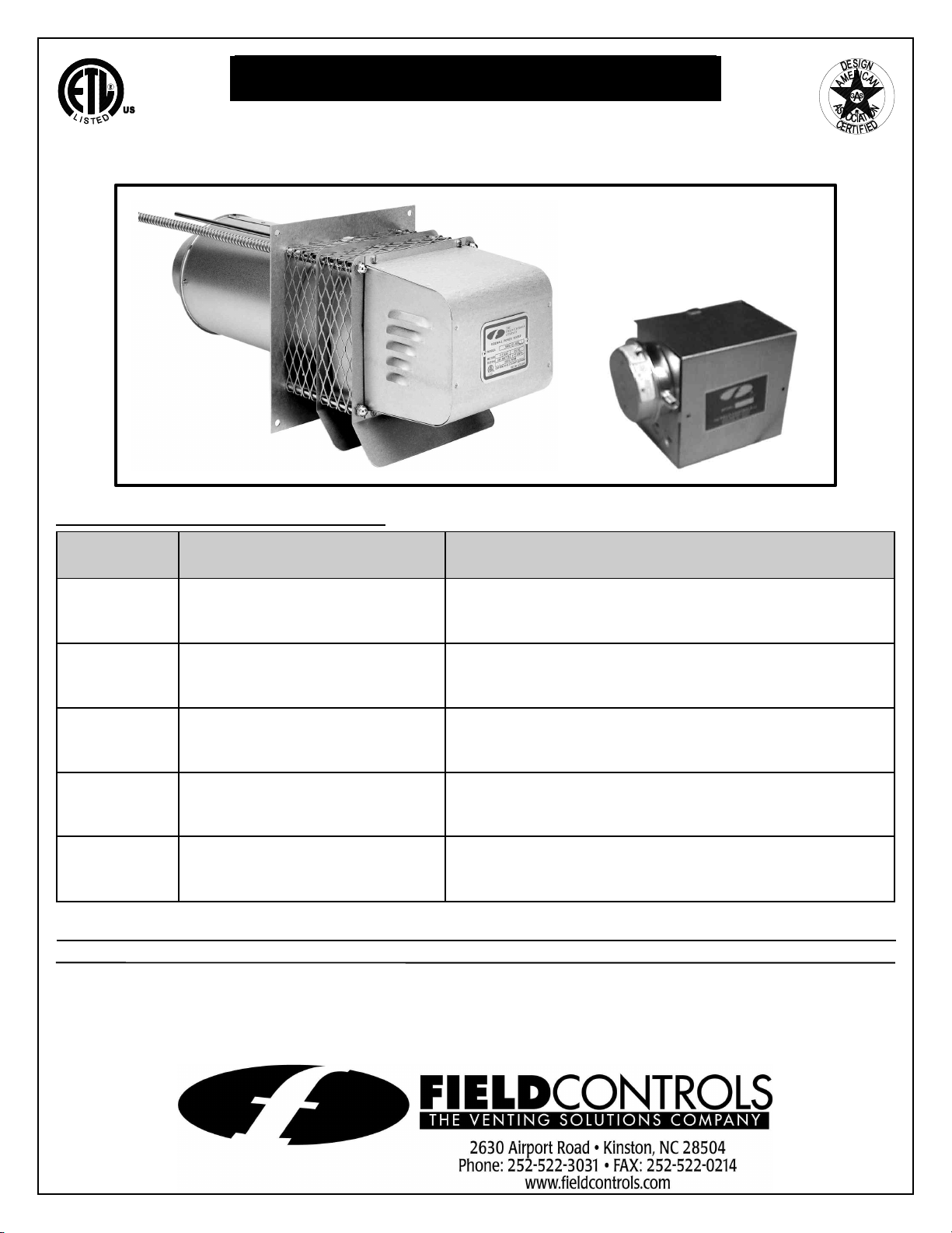
SIDEWALL POWER VENTER KIT
Model: SWGII-5,6 AGA and SWG-8*
FOR COMMERCIAL WATER HEATERS
TYPICAL VENTING SYSTEM COMPONENTS:
*Patented
PART
NUMBER
239-81764-00
239-81765-00
239-81766-00
239-81767-00
239-82148-00
DESCRIPTION APPLICATION
SWGII-5 POWER VENTER,
CK-41 24 VOLT CONTROL KIT
SWGII-5 POWER VENTER,
CK-81 MILLIVOLT CONTROL KIT
SWGII-6 POWER VENTER,
CK-41 24 VOLT CONTROL KIT
SWGII-6 POWER VENTER,
CK-81 MILLIVOLT CONTROL KIT
SWG-8 POWER VENTER,
CK-41 24 VOLT CONTROL KIT
DO NOT DESTROY
THESE INSTRUCTIONS MUST REMAIN WITH EQUIPMENT
COMMERCIAL WATER HEATERS WITH 24 VOLT
CONTROLS WITH INPUT RATINGS OF UP TO 290,000
BTU/HR.
COMMERCIAL WATER HEATERS WITH MILLIVOLT
CONTROLS WITH INPUT RATINGS OF UP TO 290,000
BTU/HR.
COMMERCIAL WATER HEATERS WITH 24 VOLT
CONTROLS WITH INPUT RATINGS GREATER THAN
290,000 BTU/HR. UP TO 416,000 BTU/HR.
COMMERCIAL WATER HEATERS WITH 24 VOLT
CONTROLS WITH INPUT RATINGS GREATER THAN
290,000 BTU/HR. UP TO 416,000 BTU/HR.
COMMERCIAL WATER HEATERS WITH 24 VOLT
CONTROLS WITH INPUT RATINGS GREATER THAN
415,000 BTU/HR.
Page 2
CONTROL KITS
Page 2
1. For 24 volt control systems (intermittent pilot ignition): CK-41 control kit with the following components: Junction box
with mounted pressure switch and relay base, 24 volt relay for controlling power venter motor, 1 ft. length of 0.25"
aluminum tubing, 0.25" tubing connector, flexible metal clad conduit, GSK-3 spillage switch, wiring harness (30 ft.
length) to connect power venter control to water heater controls, 3 cable clamps to fasten the harness.
2. For millivolt control systems (standing pilots): CK-81 control kit with the following components: Junction box with
mounted pressure switch, 115V to 24V transformer, and 24 volt relay, 1 ft. length of 0.25" aluminum tubing, 0.25"
tubing connector, flexible metal clad conduit, GSK-3 spillage switch, wiring harness (30 ft. length) to connect power
venter control to water heater controls, 3 cable clamps to fasten the harness.
GENERAL SYSTEM OPERATION
POWER VENTER KITS FOR 24 VOLT CONTROLS (CK-41 CONTROL KIT)
1. The water heater aquastat contacts close and the flue damper (if part of water heater) opens. When the damper
opens all the way, the end switch contacts in the damper motor close, completing the 24 volt circuit to the CK-41
control box causing the motor relay contacts to close and start the power venter motor.
2. When the power venter blower reaches operating speed, the resulting vacuum cause the pressure switch contacts to
close. The 24 volt control circuit flows through the pressure switch contacts in the CK-41 control box and through the
normally closed spillage switch contacts on the draft hood, completing the circuit to the ignition module on the water
heater control box. The ignitor lights the pilot and the main gas valve opens causing the main burners to light.
3. If the venting system becomes disconnected or plugged between the power venter and the water heater vent
connection, the flue products will spill out of the draft hood relief opening, heat up the spill switch temperature disc
and cause the contacts to open and interrupt power to the ignition module causing the gas valve to close and stop the
burners. If the power venter blower fails to operate, the pressure switch contacts will not close and the burners remain
off.
4. When the aquastat is satisfied, the contacts open and stop the power venter, interrupting power to the ignition module
and gas valve, and the flue damper closes.
POWER VENTER KIT FOR MILLIVOLT CONTROLS (CK-81 CONTROL KIT)
1. When the aquastat contacts close, the 24 volt circuit is completed from the transformer, through the wiring harness
and switch contacts, and through the relay coil causing the motor relay contacts to close and start the power venter
blower.
2. When the blower reaches operating speed, the vacuum near the blower causes the pressure switch contacts to close
and complete the millivolt circuit through the normally closed spill switch contacts to the gas valve, allowing main gas
to flow to the burners and ignite from the pilot.
3. If the venting system becomes disconnected or plugged between the power venter and the water heater vent
connection, the flue products will spill out of the draft hood relief opening, heat up the spill switch temperature disc
and cause the contacts to open and interrupt the millivolt circuit to the gas valve and stop all gas flow. If the power
venter blower fails to operate, the pressure switch contacts will not close and the burners remain off. If the pilot
becomes extinguished, the thermopile stops generating millivolt power and the gas valves remain closed until the pilot
is relit.
4. When the aquastat is satisfied, the contacts open and stop the power venter, causing the power to be interrupted to
the ignition module and gas valve, and the flue damper closes.
INSTALLATION SAFETY INSTRUCTIONS
CAUTION: This device must be installed by a qualified installer in accordance with the
manufacturer's installation instructions. Appliances should have a minimum of 75%
combustion efficiency or have a maximum measured flue gas temperature of 550EF at the
inlet of the power venter.
1. The power venting system must be installed by a qualified installer. "Qualified Installer"
shall mean an individual who has been properly trained or is a licensed installer. The installer must write or imprint his name, phone number and date of installation on the
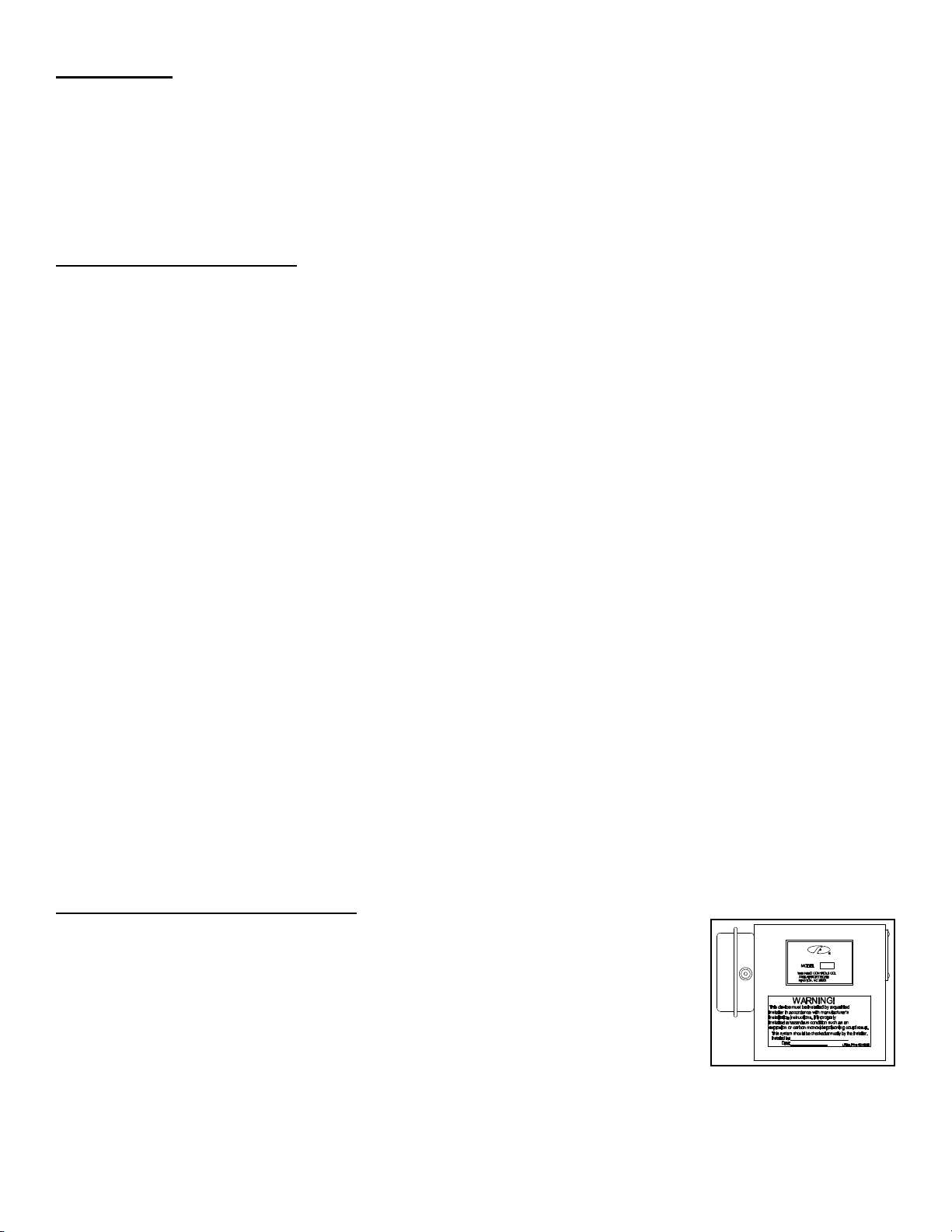
installation tag. The tag should be attached to the system control kit box or power
venter unit. Also, the included adhesive "Warning!" label should be attached to the
Control Kit box, as shown in Figure 1, and the installers name be written on it. Recording burner and venting system
initial operational information is strongly recommended as a guide for service or burner tune-up. Enter this on the back
page of this manual. The appropriate wiring diagram for the type of controls on the water heater must be affixed to the
water heater jacket upon completion of the installation.
Figure 1
Page 3
2. Safety inspection of a venting system should be performed before and after installing a power venting system on an
Page 3
existing or new appliance. Procedures to follow are those recommended by the National Fuel Gas Code,
A.N.S.I.Z223.1, or refer to General Installation Inspection section of this manual.
3. Plan the vent system layout before installation to avoid the possibility of accidental contact with concealed wiring or
plumbing inside walls.
4. Single wall vent pipe (refer to Diagram B) may be used to join an appliance to the venting system, but if proper
clearances cannot be maintained from combustible materials, Class B Vent Pipe should be used. Refer to national or
local codes for guidelines.
5. Disconnect power supply before making wiring connections to prevent electrical shock and equipment damage.
6. This equipment is designed to overcome minor negative pressure conditions. To ensure extreme negative pressure
does not exist, follow General Installation Inspection of this manual.
7. The commercial water heaters for the SWGII-5 and 6 power venters have draft hoods and each kit includes a GSK-3
spillage switch which must be installed on the bottom of the draft hood to detect spillage of flue products due to
inadequate venting draft or vent system blockage. In the event of excessive flue spillage from the draft hood, the
spillage switch will interrupt power to the gas valve to stop the burners. Refer to the installation instructions for the
spillage switch in the installation section of these instructions.
8. The power venter must be installed downstream of the appliance draft hood.
INSTALLATION OF SWG POWER VENTER
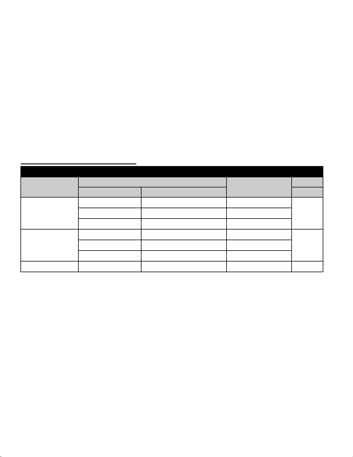
UNIT SIZING CHART
MAXIMUM BTU/HR
INPUT*
MAX. EQUIVALENT FEET OF VENT PIPE MODEL
AT MAXIMUM INPUT AT 60% OF MAXIMUM INPUT
VENTING WITH VENT
PIPE SIZE
16 44 4”
290,000
51 100 5”
95 100 6”
28 78 5”
416,000
68 100 6”
100 100 7”
505,000 65 65 10” SWG-8
*
Do not exceed maximum BTU/HR input rating.
NUMBER
SWGII-5
SWGII-6
Page 4
PROCEDURE FOR CALCULATING TOTAL EQUIVALENT PIPE LENGTH IN FEET
Page 4
1. Calculate the total equivalent feet for each type of fitting used in the venting system from the chart below.
2. Calculate the total amount of feet for the straight lengths of vent pipe.
3. Add the equivalent feet for the fittings with the total amount of feet of straight lengths. This will approximate the total
equivalent feet of the vent system.
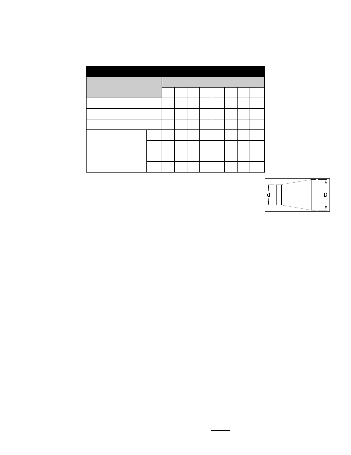
EQUIVALENT LENGTH (FEET) OF VENT PIPE FOR VENT PIPE
VENT PIPE FITTINGS
VENT PIPE DIAMETER
3” 4” 5” 6” 7” 8” 9” 10”
TEE 19 25 31 38 44 50 56 63
90° ELBOW 5 7 9 11 12 14 16 18
45° ELBOW 3 4 4 5 6 7 8 9
d/D
SUDDEN REDUCER
OR INCREASER
FOR THREE
RATIOS* (d/D)
¼ 8 11 14 17 19 22 25 28
½ 5 7 8 10 12 13 15 17
¾ 2 3 3 4 4 5 6 6
*Reducer or increaser ratio (d/D) small diameter divided by the larger diameter. (See Figure
2) Example 4" to 8" reducer: The reducer ratio is d/D = 4/8 = 1/2. To estimate the equivalent
foot length for the fitting, use the smaller pipe diameter for the equivalent length figure.
Example 4" to 8" reducer; the reducer ratio is 1/2 and the smaller pipe diameter is 4". So,
from the chart, the equivalent feet would be 7 feet.
Figure 2
Example 1: System Pipe Size = 4" Example 2: System Pipe Size =
10"
Step 1 Two 4" 90E Elbows @ 7 feet each = 14 Ft. Step 1 Fifteen 2 Foot Lengths of 10” Pipe = 30 Ft.
Step 2 Ten 2 Foot Lengths of 4" Pipe = 20 Ft. Step 2 One 10” 90° Elbow = 18 Ft.
Step 3 Total Equivalent Feet = 14 Ft. + 20 Ft. = 34 Ft. Step 3 One 8” to 10” Reducer (Use ¾) = 5 Ft.
Step 4 Total Equivalent Feet = 30 Ft. + 18 Ft. + 5 Ft. = 53 Ft.
CAUTION: Failure to install, maintain and/or operate the power venting system in accordance with manufacturer's
instructions will result in conditions which may produce bodily injury and/or property damage.
1. Remove power venter from box and inspect unit for damage. If the carton has been crushed or mutilated, check unit
very carefully for damage. Rotate blower wheel to insure that the motor and blower wheel rotate freely. DO NOT
install if any damage is apparent. Refer to unit sizing chart to check proper venting sizing.
2. Location of the termination of the venting system should be installed in accordance with the National Fuel Gas Code,
A.N.S.I.Z223.1, and/or manufacturer's recommendations which are applicable. See requirements below or refer to
installation location Diagram A for typical locations.
a. The exit termination of mechanical draft systems shall not be less than 7' above grade when located adjacent to
public walkways.
b. A venting system shall terminate at least 3' above any forced air inlet located within 10'.
c. The venting system of other than a direct vent appliance shall terminate at least 4' below, 4' horizontally from, or
1' above any door, window or gravity air inlet into the building.
d. The vent termination of a direct vent appliance with an input of 50,000 BTU's per hour or less, shall be located at
least 9" from any opening through which vented gases could enter the building. With an input over 50,000 BTU's
per hour, a 12" termination clearance shall be required.
e. The vent termination point shall not be installed closer than 3' from an inside corner of an L-shaped structure.
f. The vent termination should not be mounted directly above, or within 3' horizontally from an oil tank vent or gas
meter.
g. The bottom of the vent terminal shall be located at least 12" above finished grade.
Page 5
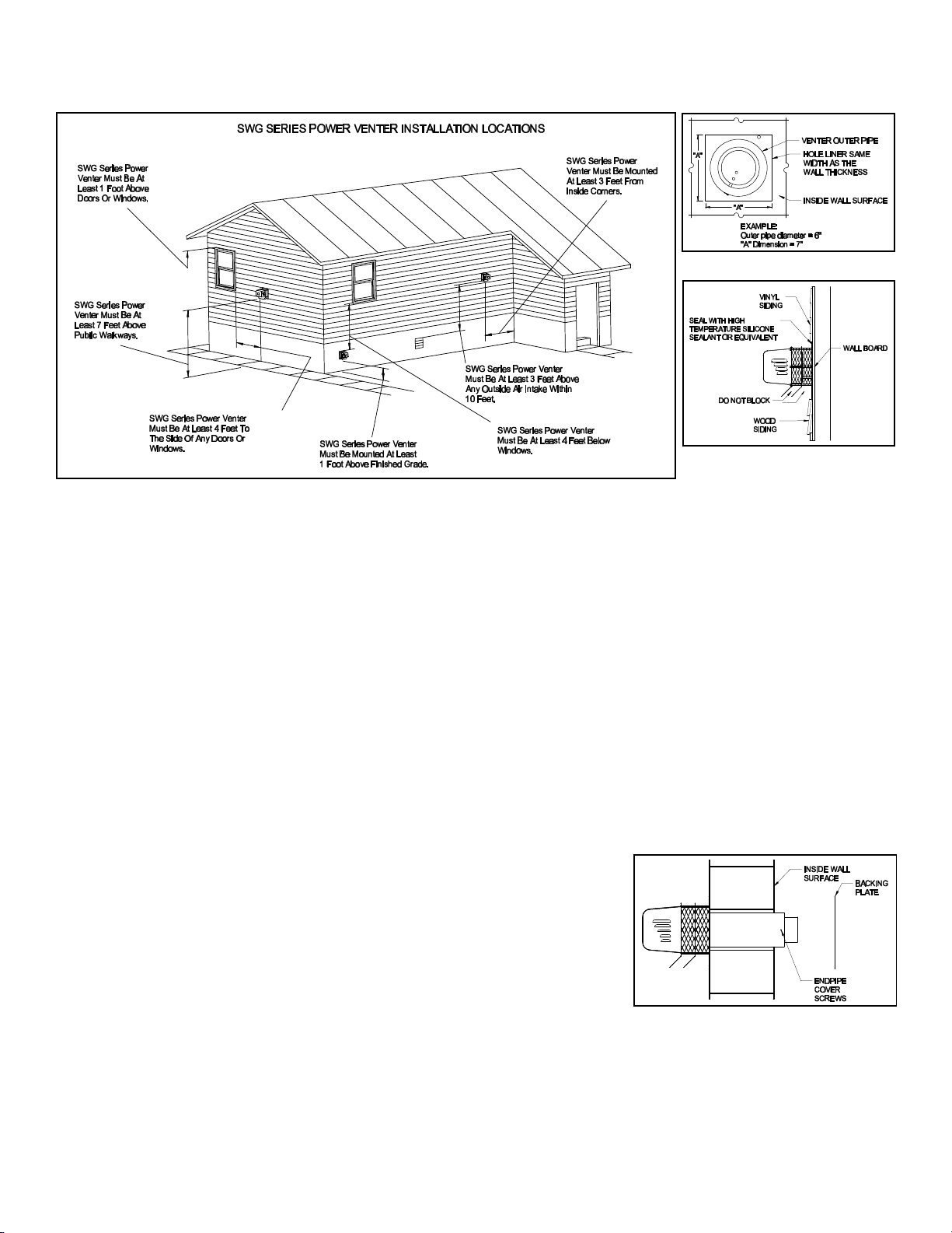
Diagram A
Page 5
Figure 3
Figure 4
3. After determining the location of the venting system termination point (See Diagram A), cut a square hole through the
wall 1" larger than the outer pipe diameter of the power venter. Mount the power venter through the wall, keeping the
outer pipe centered in the hole. (See Figure 3) Fasten the power venter to the outside wall with appropriate fasteners.
Seal the edges of the power venter base plate to the wall with a high temperature silicone sealant. DO NOT enclose
the spaced plates on the power venter body. This will result in reduced cooling of the power venter body. Galvanized
metal sheets may be installed over surrounding building surfaces to protect building materials for degradation by flue
gases. Brick or tile may be placed on the ground below the power venter to protect the soil and vegetation from the
effects of heated exhaust air. The power venter should be placed so that vegetation and other objects are not in direct
contact with the power venter or blocking the outlet. Snow should be cleared from the outlet area as needed. Wood or
vinyl siding should be cut so that the unit mounts directly on the wall board to provide a stable support. If the siding is
greater than 1/2" thick use a spacer plate or board behind the power venter mounting plate. (See Figure 4)
NOTE: If mounting the power venter through a combustible wall material and the flue gas temperature is above 400EF at
the power venter inlet, line the square hole with a piece of corrosion resistant sheet metal or non-combustible material.
The liner piece should be the same width as the wall section. (See Figure 3) The power venter has maximum flue gas
temperature of 550EF at the power venter inlet. Figure 7 shows how the airflow pattern through an SWG reduces the
required clearances to combustibles. For installation in wall thickness over 8-inches, use an SWG Series Through Wall
Extension Kit, Model PEK.
4. Remove the end pipe cover screws on the sides of the outside pipe and
remove end pipe cover. Then mount the backing plate over the outer pipe and
route the flexible conduit and pressure switch tube through the holes provided
in the backing plate. Fasten the backing plate to the inside wall with appropriate fasteners. (See Figure 5) Re-install end pipe cover and screws.
CONNECTING POWER VENTER TO APPLIANCE
Venting system should be installed and supported in accordance with the National
Flue Gas Code A.N.S.I.Z223.1, or in accordance with any local codes. A vent
pipe connector shall be supported for the design and weight of the material
Figure 5
employed, to maintain clearances, prevent physical damage and separation of joints. A vent pipe increaser or reducer
may be required for connecting the power venter to the vent system. If needed, place the reducer close to the power
venter. Smaller vent pipe sizes than a chimney-vented system may be used for the vent system.
Page 6

If mounting venting system near combustible materials, refer to Diagram B for allowable installation clearances.
Diagram B
Page 6
Clearances are based on an installation using single wall galvanized steel vent pipe. For metal thickness of galvanized
steel pipe connectors, refer to NFPA 211 or NFPA 54 Standards for guidelines. If manufactured double wall vent pipe is
required or used for the installation, clearance should be based on the vent pipes rated clearance. Always check local
code requirements for code restrictions.
Route the vent pipe from the appliance to the power venter using a minimum number of elbows as possible. The
horizontal section of the vent pipe should have a slight upward slope from the appliance to the power venter. For
clearances to combustible materials, multiple appliance venting and other installation requirements, refer to the National
Fuel Gas Code A.N.S.I.Z223.1, and/or any applicable local codes or appliance manufacturer's installation instructions.
INSTALLATION USING SINGLE WALL VENT PIPE
INSTALLATION CLEARANCE WITH SINGLE WALL VENT PIPE
DOUBLE PIPE SYSTEM SINGLE PIPE SYSTEM
ALLOWABLE INLET
TEPERATURE
CLEARANCE (A)
ALLOWABLE INLET
TEMPERATURE
CLEARANCE (B)
400°F OR LESS ½ INCH MINIMUM 400°F OR LESS 3 INCH MINIMUM
400°F TO 550°F 1 INCH MINIMUM 400°F TO 550°F 4 INCH MINIMUM
400°F TO 550°F
½ INCH MINIMUM WITH
SHEET METAL LINER
400°F TO 550°F
3 INCH MINIMUM WITH
SHEET METAL LINER
To install an outer pipe extension to the SWG power venter, the end pipe cover on the power
venter must be removed. Then, cut a 1-inch square notch into the vent pipe extension before
attaching to the power venter. (See Figure 6) This allows clearance for the adjustment damper.
Install the required length of outer pipe extension lengths as needed for clearance to combustible
materials. Terminate the outer pipe extension with the end pipe cover. (See Diagram B) The table
shows minimum allowable clearances when using single or double pipe systems. When the outer
pipe is extended over the inner pipe use the double pipe guidelines when determining clearances.
NOTE: Vent pipe joints should be secured with at least (3) three sheet metal screws.
Figure 6
Figure 7
Page 7

CLASS B AND CLASS L DOUBLE WALL VENT PIPE INSTALLATION
Page 7
(Follow vent pipe manufacturer's listed or recommended clearances from combustible material.)
5. Using a hand crimper or a like device, crimp the inner pipe of the SWG power
venter approximately 1" long. (See Figure 8)
6. Attach the vent pipe over the crimped end of the SWG power venter inner pipe.
7. Secure the vent pipe to the SWG power venter inner pipe with at least (3) three
#8 sheet metal screws. Predrilling the holes through both pipes will allow easier
fastening.
WIRING INSTRUCTIONS
Figure 8
NOTE: Refer to the appropriate wiring diagrams contained in these instructions for the corresponding control system for
the water heater being installed.
Wire the power venter motor and controls in accordance with the National Electric Code and applicable local codes. UNIT
MUST BE GROUNDED. Check ground circuit to make certain that the unit has been properly grounded. The wiring
should be protected by an over-current circuit device rated at 15 amperes. CAUTION MUST be taken to ensure that the
wiring does not come in contact with any heat source. All line voltage and safety control circuits, between the power
venter and the appliance, MUST be wired in accordance with the National Electrical Code for Class 1 wiring or equivalent.
CK-41 CONTROL KIT WIRING FOR 24 VOLT WATER HEATER CONTROLS
1. Remove the wiring harness supplied with the
control kit.
2. Remove the upper left knockout of the control
box. Push the snap bushing supplied over the
knockout hole created to prevent the wires
from being chafed. Insert the end of the
harness with quick connect terminals into the
side of the control box.
3. Disconnect the black wire connected to "TH"
or "24V" on the ignition module and connect to
the fully insulated tab on the black wire from
the wiring harness provided.
4. Connect the yellow wire from the harness
supplied to the "TH" or "24V" terminal on the
ignition module.
5. Connect the red wire from the harness
supplied to the upper terminal block (the
group of terminals opposite the yellow wire
leading to the thermostat).
6. Run the harness supplied along the water
heater jacket and support with the clamps
provided. (See Figure 9)
7.
Figure 9
Page 8

Install the GSK-3 spillage switch on the draft hood with the self-
Figure 10
Page 8
tapping sheet metal screw supplied. The thermal element disc
should hang just below the draft hood relief opening. (See
Figure 10)
8. Run the two (2) yellow wires from the break in the top of the
wiring harness into the spillage switch through the plastic
bushing opening and connect to the switch terminals.
9. Run the harness to the CK-41 junction box, which will be
mounted in a convenient location near the power venter. Use
clamps to support the wire harness to the joists at regular intervals to prevent sagging.
10. Run the low voltage wires into the control box (through hole with plastic bushing) and connect the wires as follows:
Connect the black wire to terminal T1, the red wire to T2, and the yellow wire to T3. (See Figures 11 and 12)
11. Follow the National Electrical Code and or applicable local codes for running high voltage wires to the CK-41 control
box an wire according to the diagram. Unit must be grounded. Check ground circuit to make sure the unit has been
properly grounded. Connect the flexible conduit from the blower to the control box and wire according to the diagram.
12. Attach the appropriate self-adhesive wiring diagram label to the water heater jacket.
Page 9

Figure 11
Page 9
Page 10

Figure 12
Page 10
Page 11

CK-81 CONTROL KIT WIRING FOR MILLIVOLT WATER HEATER CONTROLS
Figure 13
Page 11
1. Remove wiring harness from control kit
box.
2. Remove top knockout from the thermostat.
Push the snap bushing supplied over the
knockout hole created to prevent the wires
from being chafed. Insert wire harness
through bushing hole in thermostat top.
3. Disconnect the white jumper lead, the
white, and red leads from the thermostat
terminals. Reconnect the white wire from
the gas valve to terminal #3 (lower left) on
the thermostat. Cut the tongue terminal
from the end of the red wire to the
thermostat and strip 0.5" of insulation to
expose bare wire. Connect to bare end of
red wire from harness using wire nut or
crimp butt connector to join wires inside
thermostat housing.
4. Connect the black and yellow 24 volt wires
from the harness to the two (2) top
terminals of the thermostat.
5. Run the harness supplied along the water
heater jacket and support with the clamps
provided.
6. Install the GSK-3 spillage switch on the
draft hood with the self-tapping sheet metal
screw supplied. The thermal element disc
should hang just below the draft hood relief
opening. (See Figure 10)
7. Run the two (2) red wires from the break in
the top of the harness into the spillage
switch through the plastic bushing opening
and connect to the switch terminals.
8. Run the harness to the CK-81 junction box, which will be mounted in a convenient location near the power venter.
Use clamps to support the wire harness to the joists ar regular intervals to prevent sagging.
9. Run the harness wires through the hole with the plastic bushing in the control box and connect the wires as follows:
Connect the black wire to terminal T1, the yellow wire to T2, the blue wire to T3, and the red wire to T4. (See Wiring
Diagram, Figure 14)
10. Follow the National Electrical Code and or applicable local codes for running high voltage wires to the CK-81 control
box and wire according to the diagram. Unit must be grounded. Check ground circuit to make sure the unit has been
properly grounded. Connect the flexible conduit from the blower to the control box and wire according to the diagram.
11. Attach the appropriate self-adhesive wiring diagram label to the water heater jacket.
Page 12

PRESSURE SWITCH ADJUSTMENT
Figure 14
Figure 15
Page 12
Important: Both the CK-41 and CK-81 power vent control systems
have a pressure switch which must be properly set before the
water heater can be started. The pressure switches are set so that
the contacts will not close until properly set by the installer. Failure
to carefully follow the procedure below for setting the pressure
switch will either prevent the water heater from operating properly
of defeat the safety feature of the control which could allow a
hazardous condition to occur in the event the power venter
operates with a venting malfunction.
1. Attach the 0.25" tubing connector on the pressure tube on the
SWG venter. Connect the supplied 0.25" aluminum tubing to
the tubing connector. Route the tubing to the power venter
control box and connect the tubing to the pressure switch.
When routing the tubing, avoid kinking the tubing by bending
the tubing too sharply.
2. Follow the lighting instructions and light the pilot (millivolt
models). Turn thermostat to the highest setting and turn on
sufficient water flow to keep the burners on continually. The
power venter should start, but the main burners will not come
on until the pressure switch is adjusted.
3. Slowly rotate the pressure switch adjustment screw
counterclockwise until the contacts close and the burners fire,
then rotate the screw 1/4 turn counterclockwise. (See Figure
15) Cycle the thermostat a couple of times to insure proper
operation.
4. Follow the "General Installation Inspection " below to make
sure the pressure switch and venting system operates properly
with all gas appliances and exhaust fans operating.
GENERAL INSTALLATION INSPECTION
Recommended procedures for safety inspection of an appliance in accordance
with the National Fuel Gas Code A.N.S.I.Z223.1. The following procedure will
help evaluate the venting system. It is intended as a guide to aid in determining
that the venting system is properly installed and is in a safe condition for
continuous use. This procedure should be recognized as a generalized
procedure which cannot anticipate all situations. Accordingly, in some cases,
deviation from this procedure may be necessary to determine safe operation of
the equipment. If it is determined that a condition exists which could result in
unsafe operation, the appliance should be shut off and the owner advised of the
unsafe condition. Corrections must be made before the appliance is put into
continuous operation. The following steps should be followed in making a safety
inspection.
1. Visually inspect the venting system for proper size and determine that there is no flue gas spillage, blockage, restriction, leakage, corrosion, or other deficiency which could cause an unsafe operation.
2. Insofar as practical, close all building doors, fireplace dampers, windows, and all doors in area in which the appliance
is located. Turn on clothes dryers, any exhaust fans, such as range hoods and bathroom exhausters so they operate
at maximum speed. Do not operate a summer exhaust fan. If, after completing Steps 3 through 6 it is believed
sufficient combustion air is not available, refer to the National Fuel Gas Code A.N.S.I.Z223.1, or any applicable local
codes for guidance.
3. Place in operation the appliance being inspected. Follow the lighting instructions and adjust thermostat so appliance
will operate continuously.
4. Determine that the pilot or burner is operating properly and that the main burner ignition operates satisfactorily, by
interrupting and re-establishing the electrical power of the appliance in any convenient manner. Test the pilot or
burner safety device to determine if it is operating properly by extinguishing the pilot or disconnecting the flame safety
circuit and pressure switch sensing tube from the pressure switch.
5. Visually determine that the main burner is burning properly; i.e., no floating, lifting, or flashbacks.
Page 13

SWGII-5,6 Repair Motor Kit SWG-8 Repair Motor Kit Blower Wheel
Page 13
6. Test for spillage at draft hood opening and burner inlet air location after 5 minutes of main burner operation. Use a
draft gauge, flame of a match or candle, smoke from a cigarette, cigar or pipe. If spillage occurs, adequate air is not
available. Shut off heating appliance thermostat and check for spillage around the draft hood and burner inlet air
location after power venter has stopped operation. If a flow reversal is noticed, house depressurization is occurring
and make up air is required.
7. Turn on all fuel burning appliances within the same room so that they will operate at their maximum input. Then repeat
Steps 5 through 6.
8. Return doors, windows, exhaust fans, fireplace dampers and any other fuel-burning appliances to their previous
condition of use.
MAINTENANCE
NOTE: The installer must notify the owner/user of the device of the maintenance requirements listed below. This
instruction sheet must also be left with the owner/user.
1. Motor: Inspect the motor once a year - motor should rotate freely. To prolong the life of the motor, it should be
lubricated with six drops of SWG Superlube, Part # 46226200, annually.
2. Wheel: Inspect the power venter wheel annually to clear any soot, ash or coating which inhibits either rotation or air
flow. Remove all foreign materials before operating.
3. Vent System: Inspect all vent connections annually for looseness, for evidence of corrosion and for flue gas leakage.
Replace, seal, or tighten pipe connections if necessary.
4. System Safety Devices: With the heating system operating disconnect the pressure sensing tube from the pressure
switch on the CK Kit. This will stop the burner operation. Re-connecting the tube will relight the burner. For millivolt
operating systems, disconnect one lead of the spill switch. This will shut off the pilot and the burner. Re-connection
will allow relighting the pilot.
Should the motor or blower wheel need replacing, the following replacement items are available. The Repair Motor
Assembly contains the Motor and Blower Wheel factory assembled to a mounting bracket.
FIELD CONTROLS PART NUMBERS
MODEL REPAIR MOTOR KIT BLOWER WHEEL ONLY
SWG11-5 46234900 46150700
SWGII-6 46235000 46154600
SWG-8 46160101 46154800
REMOVAL AND INSTALLATION OF THE MOTOR ASSEMBLY
REMOVAL
1. Shut down appliance and turn off electrical supply.
2. Remove the motor enclosure cover by loosening the four screws. (See Figure 16)
3. Open the electrical box on the motor and disconnect the conduit and wires from the motor. (See Figure 17)
Page 14

4. Remove the four nuts securing the motor assembly, and pull the motor assembly straight off of the unit. (See Figure
Page 14
18)
5. Clean off any build-up inside the blower wheel housing and the blower wheel. CAUTION: Avoid applying excess pressure on the blower wheel when cleaning off any build-up of material. This will cause an imbalance of the blower wheel
which will result in excessive vibration and premature motor failure.
INSTALLATION
1. Align the holes in the circular cover plate with the holes in the motor mount bracket on the motor assembly. (See
Figure 17)
2. Slide the motor assembly onto the protruding threaded studs on the venter body with the exhaust chute pointing
downward, and replace the four nuts securely to the threaded studs.
3. Reattach the flexible conduit and wires to the motor and secure the cover on the electrical box.
4. Install the motor cover with the side louvers pointing downward.
INITIAL BURNER AND VENTING SYSTEM OPERATIONAL INFORMATION
List the following for each operating appliance on the sidewall venting system, as a guide for tune-up or service
information annually.
DATE:
Heating Appliance BTU/HR Input
Gas Valve Operation Pressure
Vent System Draft Above Draft Hood
CO2 Measurement
CO Measurement
Equipment Outlet Flue Gas Temperature
Page 15

Page 15
INSTALLATION INFORMATION
MODEL NO.:_____________________________________________________________
INSTALLER’S NAME: _____________________________________________________
INSTALLER’S COMPANY:__________________________________________________
INSTALLER’S PHONE NO.:_________________________________________________
DATE OF INSTALLATION: _________________________________________________
Page 16

PN 46256400 Rev B 7/00
 Loading...