

Page 1
This sym bol on
FIG 2
the produ ct means
the produ ct is
listed by
Underwriters
348E
Labor atories, Inc
INSTALLATION INSTRUCTIONS
& OWNER MANUAL
FIELD CONTROLS ELECTRONIC STEAM UNIT - POWER HUMIDIFIER
MODELS S2000 (120VAC) and S2020 (240VAC)
Application: Forced Air Ducted Furnaces, Heat Pumps and Air Handlers
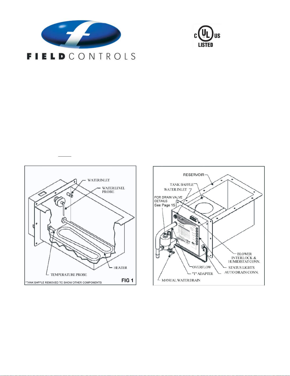
The Steam Humidi er you have purchased has been
designed to be simple to install, operate and maintain.
Read this manual before you install the humidi er.
Figures 1 and 2 will assist you in installing and maintaining
your Steam Humidi er. This product should be installed
according to local and national codes and standards.
Parts included in Steam Humidi er package are:
1. Self-piercing Saddle Valve
2. Installation Instructions and Owner’s Manual
3. Mounting Templates x2
4. Installation Hardware Package
5. Insulation and Tape
6. Automatic Drain Assembly (Shipped loose)
7. Humidistat - Model #072000 (if ordered)
8. 1/2” I.D. Drain Hose - 8 f t
9. Anode #Z100 (located on lower ange of tank ba e)
FIG 2
Options and additional parts recommended:
1. Water Hammer Arrester
2. Anode
3. Decorative Under Duct Cover
4. Gasket Material to seal anges (installer provided)
5. Model APD Current Sensing Switch, or other Air ow Proving Switch.
6. Steam Treament Water Cartridge
Page 2
Electronic Steam Unit - Power Humidi er
Table of Contents
Speci cations ................................................................................................................................2
Simpli ed Installation Instructions ........................................................................................3
Detailed Installation Instructions ...........................................................................................3
Control Wiring Solutions ..................................................................................................5, 6, 9
Dimensional Data ........................................................................................................................7
Air Ramp .........................................................................................................................................8
Variable Speed Wiring Diagram .............................................................................................9
Relative Humidity Chart ............................................................................................................9
Initial Start-Up Sequence ........................................................................................................10
Start-Up/Service Indicators ........................................................................................10, 11, 12
Service and Replacement Parts ............................................................................................13
Model 07200- Smart Digital Humidistat ............................................................................14
OAS - Outside Air Sensor ...................................................................................................16-19
Anode Assembly (Z100)...........................................................................................................20
Decorative Cover (SC100)....................................................................................................... 21
Water Hammer Arrester (WH-100)........................................................................................22
Water Conditioning System (WC-25)....................................................................................23
Air Proving Device (ADP) ........................................................................................................24
Inside Duct Mounting Bracket (IDB)....................................................................................25
Under Duct Mounting Bracket (UDB)................................................................................. 26
Water Level Probe Replacement ......................................................................................... 27
Water Fill Valve Replacement ............................................................................................... 28
page 2
Page 3
SIMPLIFIED INSTALLATION INSTRUCTIONS
1. CHECK WATER PROBE ASSEMBLY
2. ASSEMBLE/INSTALL DRAIN VALVE ASSEMBLY
3. INSULATE WATER TANK RESERVOIR
The Insulation MUST be
applied to the tank regardless of the mounting location.
4. LOCATION - Required Criteria
DO NOT INSTALL this unit in an attic period. Do Not Install
this unit in any area that may fall below 35 degrees F.
Installing unit in area 35°F or less will void your warranty!
preferred
If a suitable means of gravity draining the unit is not available
or cannot be provided, the unit will work with the drain valve
electrically disconnected. Call the Technical Support Hotline
for Instructions.
5. WEIGHT - Required Criteria
DO NOT install this unit into berglass duct without
adequate structural support!
6. MOUNTING TEMPLATES
1. Inspect water probe assembly
2. Assemble and install drain valve assembly.
3. Insulate the water reservoir. See Figure 3.
4. Select the mounting location on the duct and tape on the
mounting template.
5. Drill the (8) 1/8” mounting holes.
6. Cut out the humidi er opening in the duct.
7. Insert the humidi er into the opening and screw in place.
8. Connect the drain line.
9. Flush and connect the water line.
10. Make 24VAC electrical connections to achieve fan operation
and Interlock circuit.
11. Install and connect to humidistat.
12. Plug power cord into a grounded dedicated 120VAC, 20 amp
outlet for S2000 (240VAC, 15amp for S2020).
DETAILED INSTALLATION INSTRUCTIONS
1. CHECK WATER PROBE ASSEMBLY
Before installing drain valve assembly, inspect water probe
assembly. Heater element should be ¼” away from the brass
water temperature sensor. The wire probe must be vertical
(pointing towards bottom of reservoir). Check for alignment of
probe assembly prior to installation. Probe may have been
shifted in position or become loose during shipping. Probe
assembly must be tight and should not rotate. If loose,
remove cover and tighten water probe nut. Refer to probe
supplement insert on page 28.
2. ASSEMBLE/INSTALL DRAIN VALVE ASSEMBLY (See gure 18)
Before assembling the drain valve assembly, apply water
tight sealant to all metal to metal connections. Connect the
drain cock valve to the “T” adapter, then the “T” adapter to
the solenoid. Connect the barbed tee to the solenoid and
then connect the over ow tube. After installation, insert the
Molex plug into the right side of the steam humidi er
control panel socket.
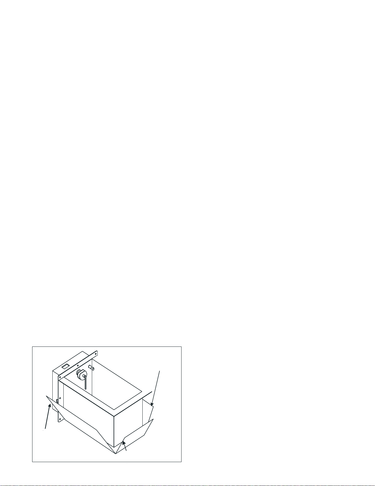
3. INSULATE WATER TANK RESERVOIR
With insulation foil side down, remove adhesive backing.
Align humidi er so that front side of unit meets long edge of
insulation. Fold insulation up onto sides of humidi er and
press rmly. Apply 5 continuous strips from the tape
provided to seal the foil as shown. The tape will prevent the
sharp duct edges from damaging the foil. Use additional foil
tape to repair damage to the foil.
applied to the tank regardless of the mounting location.
The Insulation MUST be
FIG 3
INSULATION
(FOIL SIDE OUT )
USE TAPE TO SEAL THE
FOIL TO THE FRONT
MOUNTING PLATE
(3 PLACES-SIDE AND BOTTOM)
USE TAPE TO SEAL
OUTSIDE EDGE OF
THE FOIL (2 PLACES)
4. LOCATION - Required Criteria
DO NOT INSTALL this unit in an attic period. Do Not Install
this unit in any area that may fall below 35 degrees F.
Installing unit in area 35°F or less will void your warranty!
The steam humidi er can be installed in either the warm air
supply or the cold air return ducts; however the
location would be in the warm air supply duct of the system.
This humidi er does not require warm air to evaporate the
water in order to provide humidity, but it will operate more
e ciently in the warm air duct and condensation is less likely
to occur on the surrounding cold surfaces. E ciency is lost
in a return air duct location.
When selecting a location on the duct, be certain that there is
enough room in the duct for the water reservoir. There should
be at least ve (5) inches above the reservoir and the reservoir
should not occupy more than about 25 percent of the duct
space. If this criteria cannot be met, you should install the unit
under the duct by means of the tank ange. See Figure 13 and
UDB supplement insert on page 27.
If a suitable means of gravity draining the unit is not available
or cannot be provided, the unit will work with the drain valve
electrically disconnected. Call the Technical Support Hotline
for Instructions.
It is highly recommended but not required that the use of
Fiberglass duct-board with this product includes an anti-
microbial treatment.
5. WEIGHT - Required Criteria
Providing Adequate Structural Support for this unit is the
responsibility of the Installer. It is recommended to reinforce
the cut openings with folded lengths of sheet- metal to provide
rigidity to the duct opening.
Now the screws must pass through 3 layers of metal when
inserted.
adequate structural support!
9 lbs. empty and 15 lbs when full of water.
6. MOUNTING TEMPLATES
Two mounting templates are provided. Choose the correct
template for your mounting method. Tape the mounting
template to the duct. The template must be leveled using the
top of the cutout on the template.
The template should be located so that the bottom of the
preferred
DO NOT install this unit into berglass duct without
Both models weigh approximately
page 3
Page 4
reservoir cut-out is ush with the inside of the bottom of the
7. DRILL HOLES AND CUT OPENINGS
8. WATER SUPPLY - Required Criteria
A. WATER SUPPLY USING THE SADDLE VALVE FURNISHED WITH
UNIT.
NOTE:
NOTE:
NOTE:
NOTE:
NOTE:
B. OVERFLOW & DRAIN LINES - Required Criteria
DO NOT route the hose above the
humidi er.
9. MOUNTING THE STEAM HUMIDIFIER
NOTE:
10. STEAM OPERATION - Required Criteria
duct for horizontal duct mount. Most ducts are insulated allow for
additional space, about one (1) inch, must be accounted for
when determining the location for the bottom of the reservoir
cut-out. If you are mounting it under the duct, make sure the duct
is level.
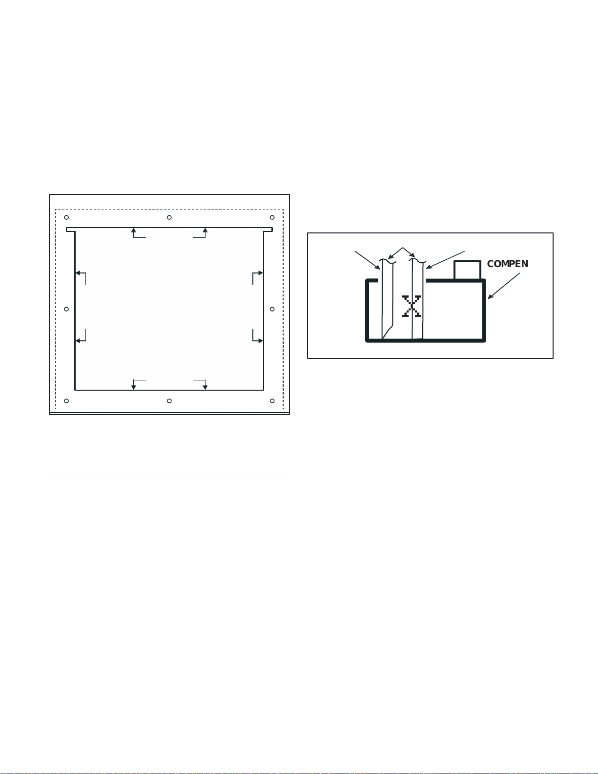
7. DRILL HOLES AND CUT OPENINGS
Safely predrill eight 1/8” diameter mounting holes in the duct.
These can be drilled through the template at the locations
indicated on the template.
Safely remove the air duct material by cutting along the
mounting template cut lines.
Insert and/or mount the Humidi er and secure it to the duct with
the provided screws.
FIG 4
B. OVERFLOW & DRAIN LINES - Required Criteria
The use of an over ow line and drain line is always required.
Use the supplied 1/2” ID high temperature hose. Slip the
hose over the 1/2” OD “T” drain tting and use a hose clamp
to secure. Route the hose to a suitable drain, avoiding kinks,
traps and sharp objects.
humidi er. Failure to install all necessary drain lines may result in water leaks during normal operating conditions, and
voids all warranties.
When routing the S2000 drain hose into a condensate
pump, be sure to cut the end of the hose at a sharp angle
to prevent the hose from bottoming out in the pan. It could
result in poor draining or no draining at all. Failure to do so
may result in water backing up into the S2000 reservoir and
eventual over ow. See Figure 5.
DO NOT route the hose above the
CUT ON LINE
MOUNTING TEMPLATE
MODEL S2000 & S2020
1. TAPE TEMPLATE IN LEVEL P OSITION.
2. DRILL (8) H OLES FOR SHEET ME TAL SC REWS
SHOWN ON TE MPLATE (DO NOT DRILL
LARGER T HAN 1/8” DIAMETER .
3. USE SOLID LI NE TO CUT OUT OPENING F OR
HUMIDIFE IR
4. MOUNT HU MIDIFIER PER INSTRU CTION.
CUT ON LINE
8. WATER SUPPLY - Required Criteria
A. WATER SUPPLY USING THE SADDLE VALVE FURNISHED WITH
UNIT.
Installation instructions for the saddle valve are printed on the
plastic bag containing the saddle valve and its components.
Tap into a 1/2” or 3/4” domestic cold water line. Avoid
connecting to water lines from a Reverse Osmosis system or
De-ionized water systems. The supply water must read a
minimum of 25 ppm in order for the Steam unit to reliably
sense the water.
NOTE: Never install the saddle valve on the bottom of the water
pipe. Sediment in the water pipe may clog the saddle valve. Flush
the line before connecting to the unit. When tightening the hex
compression nut, tighten only enough to assure there are no
leaks.
NOTE: Saddle valves do not meet plumbing codes in some areas. A
“T” tting with a valve may be required to meet code or, if low
water pressure causes frequent water alerts on the steam
humidi er.
NOTE: Flush the new water line before connecting it.
NOTE: The use of City water or Municipal water is preferred.
Softened water is preferred over untreated well water. Specify the
Optional WC-25 disposable water lter for treating any water
supply that is very high in mineral content. Refer to water
conditioning system supplement insert information on page 24.
NOTE: Use optional water hammer arrester (WH-100) if water
spikes occur (pipes bang) during ll ups. Refer to water hammer
arrester supplement insert information on page 23.
page 4
CORRECT
DRAIN HOSE
INCORRECT
COMPENSATE
PUMP
X
FIG 5
9. MOUNTING THE STEAM HUMIDIFIER
Use gasket material to seal where the front plate or tank
ange contacts the duct-work. Place the humidi er
reservoir into the opening in the duct and secure with eight
(8) sheet metal screws. Refer to page 8 and 9 for additional
humidi er mounting location information.
NOTE: If the duct-work will not support the unit in a level
position with the reservoir full of water, the duct-work
must be reinforced. Both steam models weigh approximately 9 lbs. empty and approximately 15 Lbs. when full of water.
10. STEAM OPERATION - Required Criteria
Because of the high humidity output of the steam
humid er, it must not be operated without proper fan
operation. The steam humidi er is designed to be
"Dominant" over the HVAC System Blower. The "System"
Blower will be operated by the humidi er when the water
tank temperature reaches 170° F. A minimum of 800 cfm @
800-900 fpm is required for proper operation of the steam
humidi er. Lower velocities may result in excessive
condensation inside the duct. See Air Proving Feature under
section 11 B. See Variable Speed on Page 9.
A temperature sensor is mounted in the water reservoir of
the humidi er. As the water temperature increases to about
170° F, the computer closes a set of blower relay contacts
to start the HVAC system fan. When the water cools to
about 140° F, the computer will open the relay contacts to
shut o the fan. This operational sequence drastically
decreases the chances of condensation occurring inside the
duct-work.
Page 5
11. WIRING THE STEAM HUMIDIFIER
11. WIRING THE STEAM HUMIDIFIER
IMPORTANT:
Failure to do so will void all warranties.
DO NOT
DO NOT
Doing so will void all warranties.
A. INSTALLINGAND WIRING THE HUMIDISTAT
NOTE:
Follow wiring instructions carefully!
DO NOT
connect any foreign voltage to the “H”
terminals
of the humidi er!
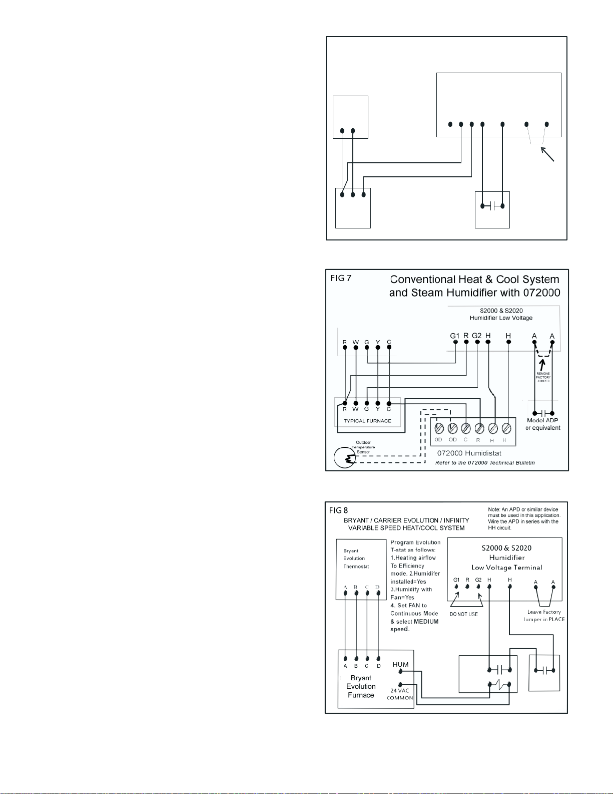
B. FIELD WIRING
AIR PROVING FEATURE:
WARNING:
IMPORTANT NOTE:
IMPORTANT: Dedicated fused circuits and outlets of the
proper voltage and current ratings must be provided. Use a
NEMA 5-20R receptacle for the S2000 and a NEMA 6-15R
receptacle for the S2020. All wiring must conform to local
and national codes.
Failure to do so will void all warranties.
DO NOT cut o the grounded plug and/or hard wire this unit
to line voltage!
unit!
Doing so will void all warranties.
A. INSTALLINGAND WIRING THE HUMIDISTAT
DO NOT use extension cords to operate this
A humidistat, such as the Model #072000 is required to
control the Steam Humidi er. The humidistat may be
installed on the wall in the living space or on the return air
duct.
NOTE: Continuous fan operation should be initiated
if the humidistat is installed on the return air duct!
Instructions for installation are packaged with each
humidistat.
DO NOT
of the humidi er! The Humidi er supplies its own control
Follow wiring instructions carefully!
connect any foreign voltage to the “H”
terminals
voltage. Simply connect the two “H” terminals straight to
any dry contact humidistat terminals.
If you are using a 3rd party Humidistat that has powered
terminals, you must use an isolating relay to operate the
Steam Humidi er. Failure to do so will result in circuit
board failure and will void all warranties.
FIG
Heat
ONLY
Thermostat
at R
R W G
Typi cal
Furnace
6
Heat Only System and
Steam Humidi er with standard
dry contact Humidistat
S2000 & S2020 Hu midi er
Low Voltage Term inal Block
G1
Dry Conta ct
Humidistat
062000 Humidistat
AHG2RH
Fact ory
Jumper will
stay in plac e
unless a eld
install ed Air
Proving Device
is used.
A
B. FIELD WIRING
Schematics on the following pages describe the
suggested interlock wiring arrangement for di erent
HVAC systems. Interlocking may be performed on systems
that provide a 24VAC NEC Class 2 terminal block for system
control.
AIR PROVING FEATURE: The Steam Humidi er has an
integrated air proving feature that allows the user to install
a current sensing switch, air ow proving switch and/or
high humidity switch in the duct and easily achieve fail safe
shutdown in the event of fan/blower failure. This feature
prevents the Steam Humidi er from operating unless
adequate air ow is proven thereby avoiding a saturated
duct condition. Refer to Air Proving Device Current Sensing
Switch Supplement insert information on page 25.
WARNING: It is highly recommended to use an air ow
proving device. In particular Duct-Board applications
should always use an air ow proving device.
A factory jumper wire is provided and must be removed
w h e n c o n n e c t i n g t h e s a f e t y s w it c h o r o th e r eld supplie d air
ow proving device. Leave the jumper in place if you
decide not to use the air ow proving feature.
IMPORTANT NOTE: If the Steam Humidi er is removed and
disconnected from the system, the blower interlock circuit
must be restored to its original con guration. Failure to do
so may result in loss of blower operation during cooling
mode.
page 5
Page 6
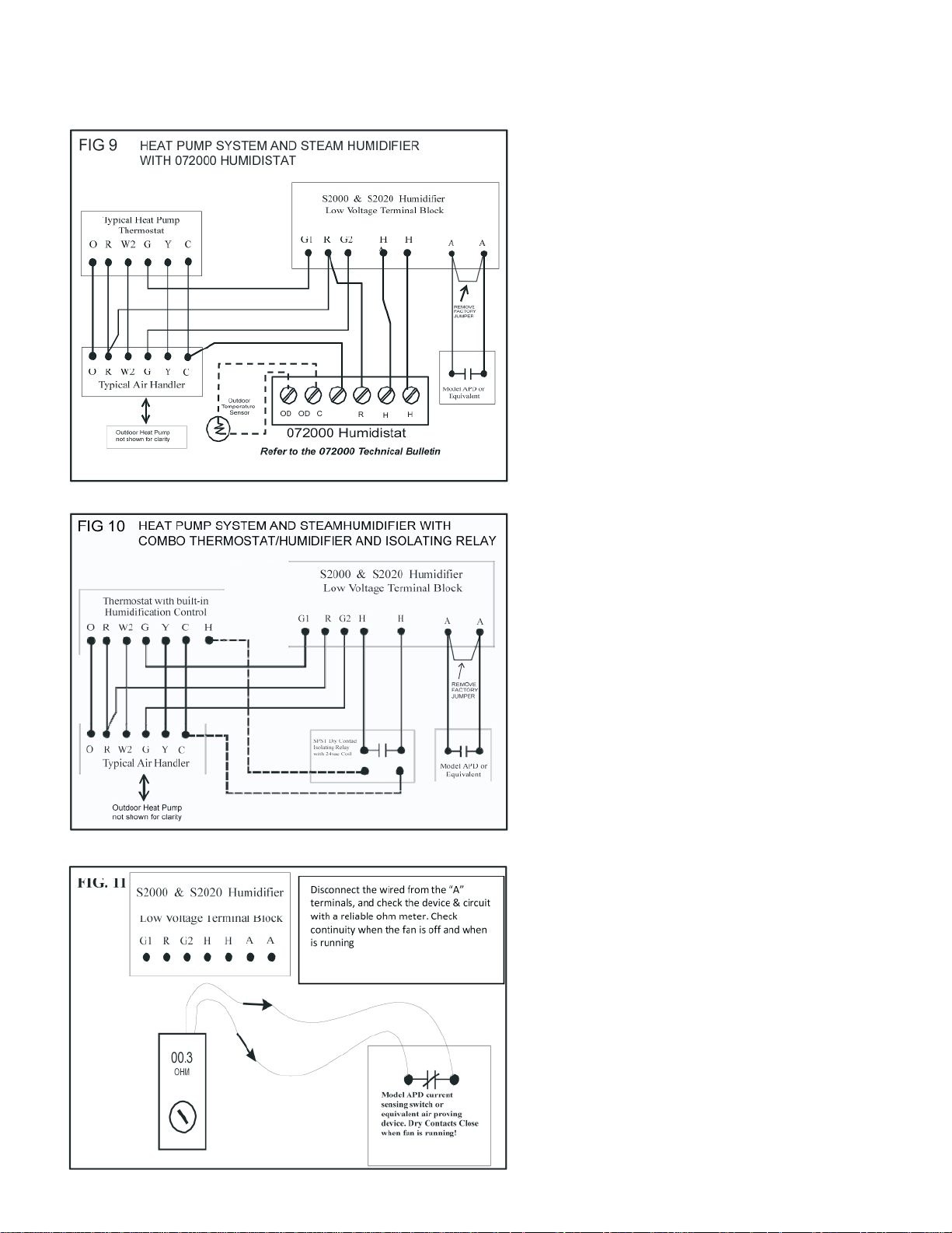
Note
WARNING: DO NOT perform this test with the wires
connected to the Steam Humidi er. Temporarily
disconnect them. Refer to Figure 11.
AIR PROVING DEVICE TEST:
CONTROL WIRING SOLUTIONS FOR VARIOUS HVAC SYSTEMS
Additional diagram shown on page 5
The latest improvement to the Field Controls
humidi ers is the new “Air ow Interlock Feature” provided
on the low voltage terminal block. Due to popular demand
we have made it easier for you to achieve fail safe lockout in
the event the fan or blower on the HVAC system does not
operate when called upon. A high humidity or air ow
proving device is necessary.
You must still determine the type of proving device you
want to use. We recommend our new Model APD switch,
(P/N: 090558A0001). Refer to APD Application
contained in this manual. But then all you have to do
is connect two low voltage wires from your air proving
device straight to the Steam Humidi er’s “A” terminals. No
additional eld relays or components are needed.
The Steam Humidi er monitors the air ow circuit
anytime it is operating the blower on the HVAC
system. If the Steam Humidi er detects a loss of air ow
longer than 1 minute, it will shutdown the heating
element and stop producing eam to avoid saturating
the duct.
You must test the air proving device when you install
it to make sure it will function properly.
Note
WARNING: DO NOT perform this test with the wires
connected to the Steam Humidi er. Temporarily
disconnect them. Refer to Figure 11.
AIR PROVING DEVICE TEST:
1. After installing the air proving device, test for
continuity across the normally open contacts with the
fan/blower o . You should read in nity (nocontinuity)
when the fan/blower is o .
2. Turn on the fan/blower at the thermostat and test for
continuity across the normally open contacts with the
fan/blower running. You should now read continuity (a
complete circuit) when the fan/blower is running.
page 6
Page 7
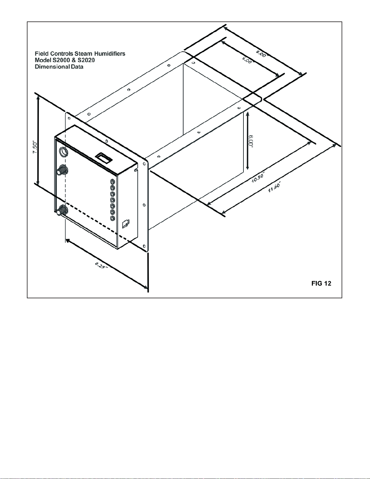
12. HUMIDIFIER MOUNTING LOCATION
12. HUMIDIFIER MOUNTING LOCATION
Figure 12 re ects the basic dimensions of the S2000 or S2020 Steam Humidi er. This data is useful in determining the room needed to
install the unit in a certain location. The data can also be used to determine the minimum duct size the Steam Humidi er can be inserted
into. The Steam Humidi er should not obstruct more than 25% of the cross sectional area of the selected duct. For Example: The humidi er tank measures 8 inches wide (including the ange) times the length of 11.6 inches=92.8 square inches. We are only concerned with the
obstruction on a at plane. Which is why the ange is taken into account but not the depth of the tank. This assumes an up- ow con guration. If the con guration is horizontal, then the Steam Humidi er will obstruct approximately 70 square inches of duct area. The tank
ange is no longer a factor.
At 92.8 square inches, the smallest duct plenum that can accommodate the Steam Humidi er mounted internally would be approximately
20” by 19”. 20x19=380 square inches multiplied by .25 = 95 square inches.
Steam Humidi er square inches of obstruction= 92.8 square inches. Up- ow con guration. 25 percent of 20x19 duct= 95 square inches.
Steam Humidi er square inches of obstruction= 69.6 square inches. Horizontal- ow con guration. 25 percent of 12x24 duct=72 square
inches.
In either case, avoid installing the Steam Humidi er on any duct size where the unit will consume more than 25% of the cross sectional
area of the duct at the point of insertion. Doing so may result in turbulent air ow, lower velocities and condensation inside the duct. Avoid
all of these conditions by selecting an “under the duct” location and specify the SC100 decorative tank cover to give it a nished look.
page 7
Page 8
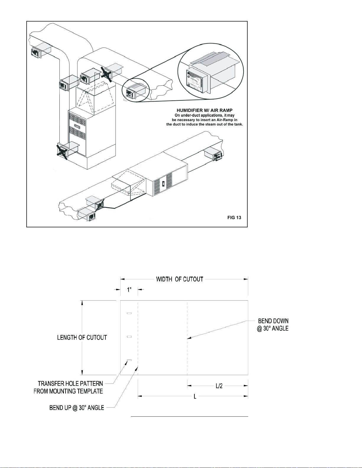
Suitable locations to install your
Caution: UV lamps may destroy certain plastics/rubber unless shielding
is applied to those surfaces.
DO NOT
DO NOT
Steam Humidi er on an Up- ow
or horizontal HVAC System. Notice
that some of the locations are X’d
out. These are poor locations for the
Steam Humidi er and may result
in lower capacity output and/or
excessive condensation. Try to avoid
mounting the unit within 2 feet of
any 90 degree turns. Allow at least 5
inche s of clearance above the tank.
The unit should not be installed
within 5 feet of an Electronic Air
Cleaner, 4-5 inch thick Media lters,
or a UV Lamp.
Caution: UV lamps may destroy certain plastics/rubber unless shielding
is applied to those surfaces.
DO NOT install the Steam Humidi er
on a Down- ow HVAC system. Avoid
Fiberglass Duct-Board as it cannot
support the weight of the Steam
unit when full of water.
stall the Steam Humidi er in an attic
or crawl space exposed to freezing
temperatures.
DO NOT in-
AIR RAMP
Improves velocity
Remember to insulate the water
reservoir with supplied insulation.
under extreme velocities it m ay be
necessary to double wrap the tank
and/or the tank ange to prevent
excessive heat loss. Also remember to
use gasket material on duct opening
to prevent metal to metal heat loss
and to prevent against condensation
and air leakage.
AIR RAMP (FOR UNDERDUCT MOUTNING ONLY)
-FABRICATE FROM CORROSION-RESISTANT SHEET METAL
(CUTOUT FROM METAL DUCT TO BE USED)
- ATTACH TO UPSTREAM EDGE OF CUTOUT
-DO NOT OBSTRUCT MORE THAN 25% OF THE DUCT AREA
page 8
Page 9
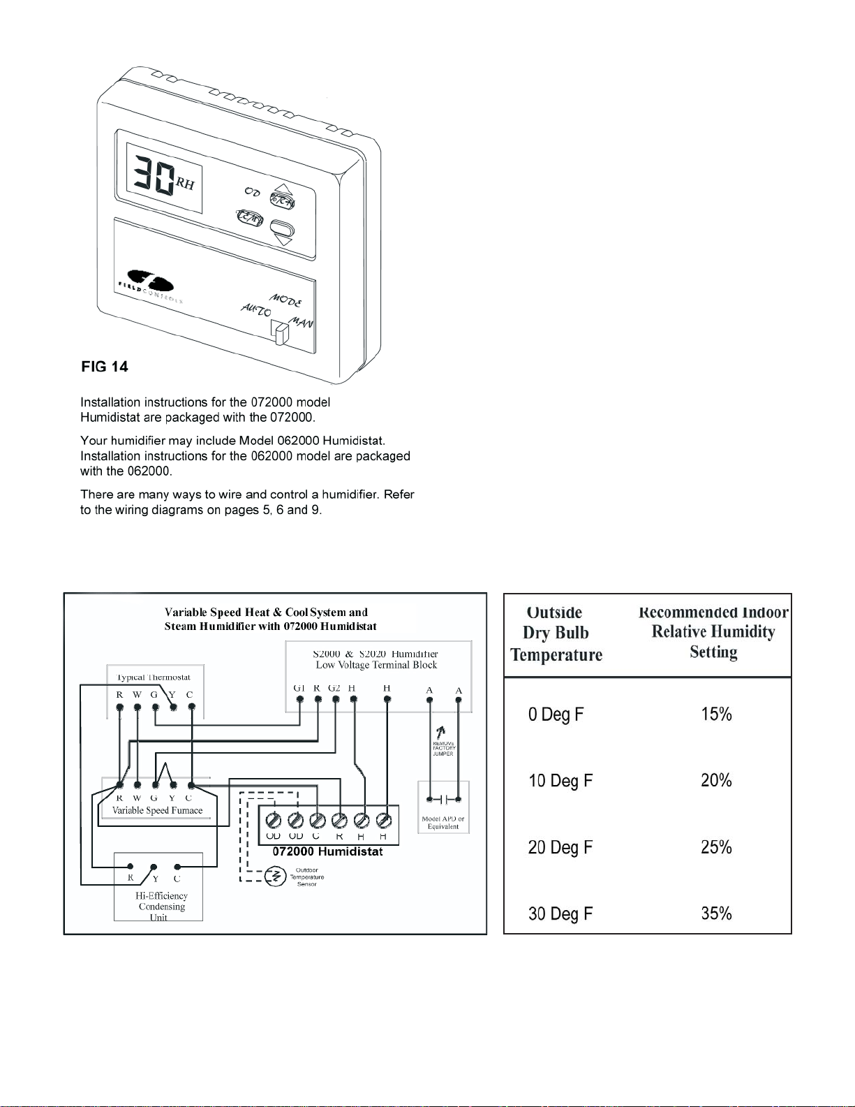
14. SETTING THE HUMIDISTAT
14. SETTING THE HUMIDISTAT
“Relative Humidity Chart”
IMPORTANT:
13. VARIABLE SPEED
It is recommended that humidistat settings of 30-45% not be
exceeded. If condensation is noticed on windows during very
cold outside temperatures, the humidistat setting should be
lowered.
The maximum recommended relative humidity for your
home depends upon many factors such as outdoor air
temperature, type and placement of insulation, vapor
barriers, e ectiveness of weather stripping, type of windows
and doors (including frames and jambs) and whether or not
storm windows and doors are used. With all these variables it
is nearly impossible to recommend a proper humidity
setting. The best humidistat setting is one that you are most
comfortable with. Also, as the outdoor temperature uctuates,
it may be necessary to adjust the humidity level of your system
a few times during the heating season.
Refer to the
your proper humidistat setting. Generally, in a tighter and better
insulated house, the humidistat may be set higher than in a
drafty, un-insulated house.
IMPORTANT: If the humidi er is installed in the return air plenum
the humidistat must be located at least ve (5) feet upstream
from the humidi er. Fan should be operated in continuous mode
when the humidistat is mounted in the return air plenum.
Mounting the humidistat on an interior wall is always preferable
to mounting on the return duct. But mounting the humidistat on
an interior wall takes more time, material and labor than a return
duct location. Sometimes it may be impossible to mount a
humidistat on an interior wall and the return duct location is the
only solution.
“Relative Humidity Chart” as a starting point for
Variable Speed WIRING DIAGRAM RELATIVE HUMIDITY CHART
FIG 15
13. VARIABLE SPEED
The diagram above should be followed if it is required to operate the fan system at high speed during the humidify operation. Such a requirement may be
necessary if condensation occurs inside the duct-work due to the lower velocities of a variable speed system when only the fan is running.
The “Y” circuit must be wired exactly as shown to achieve the correct operation. This wiring con guration may result in the loss of the “enhanced” latent
e ect operations of your variable speed HVAC system. If you do not want this to happen, you should consider installing a di erent type of whole house
humidi er that does not require dominance over the HVAC fan and full CFM capacities while operating.
Variations on this diagram are available. Contact Field Controls Technical Support Hotline.
page 9
Page 10

15. START-UP & OPERATING SEQUENCE
16. SERVICE “LED” INDICATORS
INITIAL START-UP SEQUENCE OF OPERATION SERVICE “LED” INDICATORS
NOTE:
D. BLOWER:
E. The "FILL" LED
F. DRAIN:
NOTE:
NOTE:
15. START-UP & OPERATING SEQUENCE
Once the Steam Humidi er has been installed
and the water, drain, humidistat and blower
interlock connections completed, the humidi er
may be started.
A. Disconnect the water line. Turn on the water
supply and ush the line into a bucket.
Reconnect the water line.
B. Set the humidistat to a setting higher than the
room RH level.
C. Plug the S2000 Humidi er line cord into a 120
VAC, 20 amp source. (240VAC, 15amp for S2020).
D. The Green "POWER" LED should blink rapidly and
the drain valve will open momentarily upon
initial startup. The "FILL" LED will illuminate and
water should begin to ll the Water Pan. The
Power LED will now blink slowly.
E. When the water has reached the probe level
the "FILL" lamp and ll valve will be turned o ,
and the "HEATER" LED and heater element will
be turned on. The “POWER” LED will blink slow
and steady.
F. Once the water reaches 170 deg. F. the
"BLOWER" LED will illuminate and the system
blower should start up.
G. If the above steps have been successfully
completed, the humidi er is operating properly.
16. SERVICE “LED” INDICATORS
A. POWER: In normal standby mode, when the
humidistat is not calling for humidity and the
power cord is plugged in, the "POWER" LED
should be blinking slowly. If the green "POWER"
LED is not ashing when there is power to the
unit, the CPU and/or circuit board may have
failed.
B. FILL: When the humidistat closes, on a call
for humidity, the "FILL" LED is illuminated, the
Solenoid Valve is open and the water reservoir is
lling.
C. HEATER: When the water reaches its proper
level the valve closes, the "FILL" LED goes out,
the "HEATER" LED is illuminated, and the
Heater begins to heat the water.
NOTE: If the humidi er is unplugged while in
steaming operation and then plugged back in, a
rapid ashing of the “POWER” LED will occur
and all other functions will stop! The unit wants
to perform a water probe test, but cannot
perform this test until the water cools down.
Simply wait until the unit cools down and it will
resume normal operations. To accelerate a cool
down, simply turn the HVAC system fan on via
the thermostat.
D. BLOWER: When the water in the reservoir reaches
approximately 170 deg. F. the "BLOWER" LED will
be illuminated and the interlock wiring should turn
the system blower on. Depending upon the water
and ambient temperatures, it may take anywhere
from four to twelve minutes for the water to heat
to 170 deg. F. If the humidistat remains closed the
"HEATER" and "BLOWER" LED's will both be illumi
nated at the sametime and the "POWER" LED will
be blinking slowly.
E. The "FILL" LED will illuminate and the water
reservoir will re ll at irregular intervals, depending
on the boil o rate. The "HEATER" LED should
remain illuminated unless the humidistat opens or
the humidi er enters a drain cycle or failure mode.
. DRAIN: This LED will be illuminated when the
microprocessor cycles the humidi er into a Mainte
nance Mode. After a fan forced cool down period,
the water is allowed to drain at 140 degrees F. The
drain valve will then close and the ll valve will open
to re ll the reservoir and resume normal operation.
This mode will last about one hour and the micro
processor will automatically restart the unit after
wards, if there is a call for humidity. This drain cycle
will occur once every 8-12hours, to reduce the min
eral concentration in the tank and let the heater
cool- down. That will shed most deposits that have
built up on the heater.
NOTE: The "POWER" LED will blink rapidly during
Maintenance mode.
NOTE: A unique feature of the “S” series humidi ers is
called “Fill on Request”. The unit will not re ll
with water after a maintenance cycle, unless
there is a demand for humidity from the
humidistat. This ensures that the unit will not sit
idle with standing water, which can stagnate
over time.
page 10
Page 11

G. FAILURE LED'S:
17. MAINTENANCE/SPRING SHUTDOWN
NOTE:
When service is required, these LED's will illuminate. If the
humidi er enters a failure mode, it must be manually re
set by disconnecting the power and then reconnecting it.
If the “Air” failure LED occurs, simply turn the Humidistat
o or down then back up again to reset.
WATER:
This will occur when the reservoir is not lling up with
water, not lling fast enough or the microprocessor
cannot recognize that the water is touching the probe.
Reverse Osmosis water or puri ed (distilled/deionized)
water sources should be avoided, unless the nal feed
water measures at least 25 ppm conductivity.
HEATER:
This will occur if the humidi er is notboiling o water
during the "HEATER" cycle. Water in the reservoir is not
reaching 170 deg. F. temperature, or the unit has not de
tected a request for water in a 50 minute steaming time
period. Both red LED’s will illuminate in this condition.
AIR:
This will occur if the humidi er detects a loss of air ow
for more than 4 minutes. A eld supplied air proving
device must be installed, wired and tested.
A. Unplug the power cord from the 120 volt source for
S2000 (240 volt for S2020) and allow the water to cool for
at least 30 minutes prior to removal.
B. Turn o the water supply at the saddle tapping valve.
C. Remove the cable assembly wire plug from the top of the
plastic control housing
D. Drain the water with the manual drain valve. NOTE: The
drain valve will be hot if the humidi er has not been
allowed to cool.
E. Disconnect the water and drain lines. NOTE: Some water
may drain out of the water line. Have a small container
ready to catch the water.
NOTE: Although the water has been drained, some
water may still remain in the humidi er reservoir
along with sediment. Be careful not to tip the unit
over when removing it from the duct.
Remove the eight (8) screws from the front
mounting plate.
F. Slide the humidi er out of the duct.
THERMISTOR:
This will occur if a short or open is detected in the tem
perature probe.
17. MAINTENANCE/SPRING SHUTDOWN
Proper maintenance and removal of mineral deposits is still
required on your steam humidi er in order to optimize per
formance. Annual cleaning is a must and more frequent
cleaning may be necessary depending on the mineral
content.
A post winter cleaning and shutdown, will prevent hard
deposits from accumulating inside the bin, while the hu
midi er is idle over the summer. Do not allow the unit to
sit idle for long periods without proper cleaning and
shutdown. Failure to do so will a ect the performance of
your system.
Maintenance and inspection of the unit requires removal of
the humidi er from the duct. This can be done following
these steps.
G. Remove the two (2) screws holding the tank ba e to the
pan ange and remove the ba e from the unit. Scrape
all mineral deposits from the ba e and wash ba e o
as described in step J. Remove the Anode from the ba e
plate and purchase a new one. Operating the unit without
the Anode will degrade the performance and increase
maintenance.
H. Use a putty knife to scrape the minerals from the sides
and bottom of the water reservoir. DO NOT scrape on
the small temperature probe, or the heater element. Use a
soft Emory cloth or sti nylon brush. If necessary, ll the
tank with vinegar and let it sit for several hours or even
over-night allowing the scale to soften and making it
easier to remove.
I. Carefully scrape the Water Level Probe to remove
mineral deposits. Use soft Emory cloth if necessary
J. Clean with water probe insulator, inside the pan, with 50-
50 mixture of water and vinegar, rinse with fresh water,
Inspect for any material deposits on the plastic insulator.
Repeat cleaning if necessary and thoroughly dry. Use a
small nylon brush to clean deposits o the heater element
and thermistor probe. Be careful not to damage any of
the components.
K. Rinse out the reservoir. Be careful to keep water o of
the wiring compartment and the front cover of the
humidi er. Allowing the unit to dry thoroughly before
using.
page 11
L. Re-install the tank ba e and tighten the two (2) screws.
M. Re-install the unit in the duct and connect the water lineand the
drain lines. Store the unit in this condition for the summer, or
continue to the next step.
Page 12

START –UP
18. SERVICE INDICATORS
N. Turn on the water supply. Inspect the water connections and drain ttings for leaks.
O. Turn on the water supply. Inspect the water connections and drain ttings for leaks.
1. The green POWER light should blink rapidly until it detects a demand to humidify, then it will blink slowly.
2. If the humidistat is calling for humidity the water valve will energize and the water pan will ll with water.
3. The Heater element will energize to heat the water, and the Fan will start up to distribute the moisture.
18. SERVICE INDICATORS
Nine LED lamps provided on the front panel indicate the functional status of the humidi er as shown in Figure 16 below.
page 12
FIG 16
Page 13

A. The green "Power" light does not blink o and on.
DO NOT
This will void the warranty.
1. The S2000 is not connected to an active 120 VAC 15 Amp
power source. (S2020, 240 VAC, 10 AMP).
2. Call the Technical Support Hotline.
B. The "HEATER" LED does not illuminate.
1. The humidistat is not closed, calling for humidity or the
humidistat is wired incorrectly.
2. The unit is in the maintenance cycle.
C. The HVAC Blower will not operate, but the "Blower" LED is
on.
1. The blower "Field" wiring and/or interlock circuitry is
incorrect.
2. The HVAC electric power is disconnected.
3. The humidi er internal "Blower" relay is defective. Call
the Technical Support Hotline.
4. The HVAC Blower motor has failed.
D. The HVAC Blower will not operate and the "Blower"
LED is not on.
The water pan temperature has not reached a high
enough temperature to activate the "Blower" relay, about
170 degrees Fahrenheit. This takes several minutes after
the "HEATER" LED is illuminated. Depending on the water
temperature and the surrounding condition, this may take
up to 12 minutes. If the problem continues, the heater
element may be defective or the thermistor temperature
probe may be defective. Contact the Technical Support
Hotline.
E. Red Service Light (error #1) is on constantly.
THERMISTOR FAILURE ...This is an indication that the
temperature probe is open or shorted to ground. May also
indicate the probe has detected a pan temperature below
32 degrees F. Or in excess of 230 degrees F., resulting in a
total shutdown. Try to reset the unit by unplugging the
cord and Reconnecting, or call Technical Support.
F. Red Service Light (error #2) is on constantly.
WATER FAILURE ...This is an indication that the water ll
time has been exceeded. The water level did not reach the
probe tip in the given amount of time. It may also indicate
an unsuccessful drain cycle.
1. The water line is shut o at the saddle valve.
2. The water line is crimped or pinched.
3. The water valve inlet screen is plugged. Remove the
water line from the unit and check the screen found
inside the inlet side of the valve.
4. Unit is connected to a water source which is distilled,
over- ltered, de-mineralized, or from a reverse osmosis
system. Minimum 25 ppm water conductivity is
required. *The unit supply water must contain dissolved
solids in the water, or the processor will not be able to
detect the water level.
5. The water valve may be defective and must be replaced.
See replacement parts.
6. The drain valve is unplugged or defective.
7 Debris is clogging the drain valve or drain line.
8. Reset the unit by unplugging the power cord and recon
necting.
G. Both Red Service Lights (error #3) are on constantly.
HEATER FAILURE...This is an indication that the water
temperature is not increasing or reaching the boiling
point.
1. Faulty heater element or faulty wire connection.
2. This can happen if the unit is operated without water in the
pan as a result of a water level probe malfunction, due to
lack of maintenance. The pan boils dry and overheats the
water pan. If this condition occurs, call the Technical
Support Hotline.
3.
The unit has operated for 45-50 minutes without a
request for water, due to a leaking water ll valve, which
is lling the tank continuously.
4. Check drain solenoid valve for leaking around valve seat.
Clean valve by ushing or replace solenoid valve.
H. Both Red Service Lights (error #4) are ashing.
AIRFLOW FAILURE… This is an indication that the
system blower is not running or the blower/fan proving
device has failed, is malfunctioning, or is not wired
correctly. Check the blower motor and the interlock wiring.
Refer to page 4, Figure 11.
I. If the humidi er seems to operate in a random manner that
doesn't seem to t any of the pre-described conditions,
check the following:
1. Check to make sure that the wires used to connect the
humidi er to the humidistat are separate wires and not
part of a multi-wire bundle used to hook up the furnace
thermostat or any other device. The associated close
wires may create an induced voltage in the humidistat
wiring.
2. Make sure that the water level probe and plastic insulator are
clean and free of mineral build-up. It may become electrically
conductive to ground, sensing a false indication that the
water level is correct.
3. If the electric solenoid valve makes a loud noise when it
closes, install an optional water hammer arrester to absorb
the spike. Frequent or erratic water ll cycles can be due
to air turbulence, when mounted in the supply air plenum.
4.
The water probe uses the natural conductivity of the
water, to determine the proper water level in the reservoir.
Water that has been de-mineralized or over ltered may
not allow the unit to function properly. Minimum 25 ppm
of total dissolved solids must be present in the water.
Add approximately 1 tablespoon of salt to the tank, to
temporarily x this problem.
5. These steam humidi ers must be connected to dedicated
outlets of the proper current and voltage ratings. The use
of extension cords is not recommended.
DO NOT cut o the
grounded plug and/or hard wire this humidi er to line
voltage.
This will void the warranty.
page 13
Page 14

SERVICE AND
REPLACEMENT PARTS
page 14
FIG 17
Page 15

page 15
Page 16

NOTE:
Your new Steam
Humidi er may
include this
control. The
instructions are
included! Please
refer to this Bulletin.
Field Controls
Model 07200 - Smart Digital Humidistat
General Description
The 072000 is a digital humidi er control that can automatically
adjust the indoor humidity set point as the outside air temperature
changes. This intelligent control will maintain accurate humidity
levels and a more comfortable indoor environment.
The actual indoor relative humidity is always on the LCD screen.
When teh up or down keys are pressed, the humidity set point is
displayed and can be adjusted using the up or down arrown keys.
An outdoor temperature sensor is included, and must be connected in order to fully utilize the features of the 072000. The outdoor
temperature sensor allows the humidistat to automatically adjust the
humidity set point, to avoid condensation on windows. It is also
a convenient way to read the outdoor air temperature at any time.
Package includes:
1 #072000 Smart Humidistat
1 Foam Gasket
1 Mounting Template
1 Technical Bulletin #TB213
2 Mounting screws
2 Wall anchors
1 #OAS outside Air Sensor
The outdoor sensor is not required to use the Humidistat in the
basic or manual mode.
The 072000 operates on 24VAC, and has a set of isolated dry
contacts for activating the humidi er. Terminals are also provided
for the Outdoor Air Temperature Sensor. (Part# OAS)
The 072000 can be installed on the Return air duct or, it can be
installed on an interior wall within the conditioned space. Field
Controls recommends an interior wall installation.
return air duct is chosen as the location, the HVAC fan should
be set to run continuously, in order to obtain an accurate sampling of the actual living space relative humidity condition.
NOTE: If the
page 16
Page 17

APPLICATION NOTE
The OAS comes standard with the 072000 Smart Digital Humidity Control. Refer to the 072000 Technical Bulletin
for the speci c Outside Air Features & Functions provided.
Model OAS
(OUTSIDE Air Sensor)
The OAS comes standard with the 072000 Smart Digital Humidity Control. Refer to the 072000 Technical Bulletin
for the speci c Outside Air Features & Functions provided.
The OAS is a versatile device because it can be mounted on an outside wall or an outside air duct. See Page 2 & 3.
Make sure the OAS is mounted completely outside of the house, on the North, East, or West side of the building.
Avoid direct sunlight. Do not mount the OAS low to the ground where snow can cover it. Do not mount the OAS
close to exhaust vents of any typ. Use a dedicated 2 conductor 18AWG solid copper jacketed thermostat cable to
connect the OAS to the Smart Humidistat. Avoid running cable in close proximity to line voltage circuits, or inside a
conduit with other circuits. Avoid wire runs in excess of 100 ft.
The Sensor wiring is not polarity sensitive. OAS equipped panels have a designated terminal block for the OAS.
Be sure to enable the OAS Dip switch. Now dial in the Outside Air Changeover setting you desire. Dual fuel Heat
Pumps and Multi-Stage heating systems can be controlled without the need for bulky mechanical outside air thermostats or expensive dual fuel kits. To test and OAS disconnect the wire leads from the control panel and remove
it from the duct. At room temperature (75F.) the ohm reading on an OAS will be approximately 10.5K ohms (10,500
ohms). Or leave the OAS where it is and place a separate temperature probe of known accuracy in the same location as the OAS and measure the OAS resistance against the table provided on page 4. You should measure a value
within 5% of the table value and the separate temperature probe reading.
page 17
Page 18

Model OAS
(OUTSIDE Air Sensor)
Choose a suitable location to mount the OAS. The OAS can be con gured to mount on an outside air duct or an
outside wall. If mounting on a wall, simply fasten the box to the outside wall using the two ¼” hex head self-tapping screws and wall anchors provided. The box should cover the hole penetration made in the wall. Now route
2x18AWG eld wire through the center hole and into the box. Press the sensor into the brackets on the underside
of the front cover. Use the provided wire nuts to connect to the SAS sensor wires. Place the cover back on and
secure it. Connect the #18AWG eld wires to the correct terminals on your Field Controls control panel. The ¼”
bracketed tube and rubber end cap are not used in this con guration.
page 18
Page 19

Model OAS
(OUTSIDE Air Sensor)
Choose a suitable location to mount the OAS. The OAS can be con gured to mount on an outside air duct or an
outside wall. If mounting on a duct, make sure there are no critical components behind the duct and drill a 3/8”
hole into the duct. Assemble the components as shown below to allow the sensor to sense outside air moving
through the duct. Now fasten the box to the duct using the two ¼” hex head self tapping screws provided. Route
2x18AWG eld wire through the wire entrance grommet and into the box. Use the provided wire nuts to connect
to the OAS sensor wires. Place the cover back on and secure it. Connect the #18AWG eld wires to the correct terminals on your eld controls control panel. NOTE: Choose your sensor location and con guration carefully. Sensing
Outside Air Temperature in a duct can lead to inaccurate readings if the air is not actually moving through the duct.
page 19
Page 20

Model OAS
(OUTSIDE Air Sensor)
The “OAS” is constructed of UV stabilized Poly Carbonate Plastic with seamless aluminum tubing frame and highly
accurate thermistor with 24AWG 12” leads. The unique construction provides a thermal barrier between the temperature probe and the duct work allowing precise air temperature measurements.
To test OAS, disconnect the wire leads from the control panel and remove it from the duct. At room temperature
(75°F.) The ohm reading on an OAS will be approximately 10.5K ohms (10,500 ohms). Or leave the OAS where it
is and place a separate temperature probe of known accuracy in the same location as the OAS and measure the
OAS resistance against the table provided below. You should measure a value within 5% of the table value and the
separate probe reading.
page 20
Page 21

APPLICATION NOTE
Z100 ASSEMBLY (P/N: 094021A0211)
Anode Installation Instructions
The Field Controls Steam Humidi er now comes equipped with a factory installed Z100, which acts as a sacri cial
metal. Put simply, minerals in the water will attack and cling to the Z100. The minerals will not attack the other
components inside the humidi er as long as the Z100 is present and active.
This results in a dramatic decrease in mineral and scale build up on the critical components inside the tank.
In particular, it means less scale build up on the heating element which is subject to damage from excessive
scaling and overheating. This also means that e ciency stays high and preventive maintenance is faster and easier.
The Z100 is positioned on the ba e plate inside the tank and is easily removed and replaced. Remember
that the Z100’s job is to become the target of mineral attack, so it will be heavily covered with scale and should be
replaced annually for best results.
To remove the Z100 you must have already unplugged and shutdown your steam humidi er and allowed it to cool.
The water tank has been drained, the water supply, drain lines and electrical wiring have been disconnected and the
unit has been removed from the duct.
Refer to the blow up view on Page 11. Using a Philips screwdriver, remove the two screws that hold the ba e plate
to the tank. Lift the ba e slightly back to clear the water probe and then straight up and out of the tank. You can
then see the round Z100, or rather what is left of it after a single season. Notice the heavy scale build up on the
Z100 that would have been on your element, if the Z100 was not there. Use a rag or pliers to grasp the edges of
the Z100 and simply unscrew it from the ba e plate. Rinse o or wipe away any residual scale from the ba e plate
and install a new Z100. Leave a slight gap between the bottom of the Z100 and the ba e plate. Now re-insert the
ba e plate into the tank and secure with the two screws that were removed previously. It’s that simple.
The Z100 can also bene t the older model steam humidi ers. Simply lay the Z100 down into the ba e plate in the
same location as the factory installed model. DO NOT lay the Z100 down into the main tank. It may come in contact
with the heating element and damage it. The dimensions of the ba e plate prevent the Z100 from falling
down into the tank.
page 21
Page 22

APPLICATION NOTE
Decorative Cover
SC100 (P/N: 094021A0156)
Supplement to the Electronic Steam Power Humi er
Model # S2000 and S2020
The Field Controls Steam Humidi er can be equipped with a eld installed Decorative and Protective Cover
for Under the Duct Installations only. The SC100 provides a protective shell around the exposed insulated
tank and provides a visually pleasing nish to the installation.
The SC100 decorative cover is available as an installation add-on option for the steam humidi er. Contact
your local Field Controls Contractor (installer) for purchase.
page 22
Page 23

CAUTION
APPLICATION NOTE
Model #WH-100 (P/N: 090478A0001)
Water Hammer Arrester
Installation Instructions
Supplement to the Electronic Steam Humidi er
Model S2000/S2020
Parts List:
* Water Hammer Arrester #WH 100
* 2 - 1/4” brass compression nuts
* 2 - 1/4” brass ferrules
* 2 - 1/4” plastic ferrules
Water Hammer is the term used to de ne the pounding noise or vibration that occurs in a water line, due to the
fast closing action of electric solenoid valves or similar water ow control devices.
Installation of a water hammer arrester will cure this problem and allow your humidi er to work quietly and
e ciently.
Required tools and materials:
* Adjustable wrenches
* Tubing cutter
1. Identify a suitable location to install the arrester.
2. The preferred location of the arrester is on a horizontal or vertical section of the ¼” water line close to the
humidi er. Approximately 6-12 inches from the connection to the humidi er.
3. Unplug the humidi er, and turn o the water supply to the humidi er.
4. Cut the water line, 1/4” copper or plastic tubing.
5. Slide the 1/4” brass nuts and ferrules onto each end of the water line.
6. Use the plastic ferrules if installing the arrester onto plastic tubing.
CAUTION: provide support for plastic water lines which cannot handle the weight of the water hammer arrester.
7.
8. Install the water hammer arrester and tighten the connections. DO NOT OVER TIGHTEN.
9. Turn on water supply, and plug the humidi er back in.
10. Inspect for water leaks and observe humidi er operation.
11. Congratulations ! You have successfully installed the water hammer arrester.
page 23
Page 24

APPLICATION NOTE
Model #WC-25 (P/N: 094021A1122)
Water Conditioning System
Supplement to the Electronic Steam Humidi er
Model S2000/S2020
FAILURE TO READ AND FOLLOW INSTRUCTIONS CAREFULLY BEFORE INSTALLATION OR
OPERATION COULD DAMAGE THIS DEVICE OR CAUSE PROPERTY DAMAGE.
KEEP HUMIDIFIERS CLEAN AND SCALE-FREE!
Description:
Steam-Treatment Water Conditioning System (STEAM-TREAT) is
designed for humidi ers using up to 25 gallons per day and will
inhibit scale for one season. Install Steam-Treat on the 1/4” food
grade poly vinyl cold water tubing that supplies water
directly to the humidi er. Equipped with John Guest Fittings.
The STEAM-TREAT System is available as an installation add-on
option for the Steam Humidi er S2000, S2020 and Atomizing
Humidi er TM-2000.
Application:
Clean tank and heating element and if necessary clean or install
new pad before installing the Steam-Treat cartridge.
For best results, humidi er should have a daily dump of water
from the sump to diminish scale forming minerals.
Install a new Steam-Treat cartridge before each heating season.
Operating temperature, min./max, 40°-80°F (4-26°C).
Installation Steps:
1. Shut o the water supply to your humidi er.
2. Disconnect existing cartridge or cut water tubing where new
cartridge is to be installed.
3. TAP INTO COLD WATER PIPE ONLY. DO NOT USE HOT WATER.
4. Use 1/4” food grade poly vinyl water tubing only. (DO NOT
USE COPPER) Insert the poly vinyl tubing directly into the John
Guest ttings at each end of the Steam-Treat cartridge. No additional ttings or tools are necessary.
5. Observe proper direction of water ow.
6. Carefully turn on the water and check for leaks.
7. Check the Cartridge after approximately 8 hours for slight
leaks not visible during original installation.
page 24
Page 25

APPLICATION NOTE
Model #APD (P/N: 090558A0001)
Air Proving Device Current Sensing Switch
Installation Instructions
Supplement to the Electronic Steam Humidi er
Model S2000/S2020
The Field Controls Steam Humidi er can be equipped with the Air Proving Device (APD). Field Controls provides a current sensing switch
type device. This device must be purchased seperately from Field Controls as part of your Steam Humidi er System.
The latest improvement to the Field Controls humidi ers is the new “Air ow Interlock Feature” provided on the low voltage terminal block.
Due to popular demand we have made it easier for you to achieve fail safe lockout in the event the fan or blower on the HVAC system does
not operate when called upon. A high humidity or air ow proving device is necessary.
INSTALLATION:
1. Ensure power conductor to be monitored is disconnected and
locked out from the power source!
2. Install the removable mounting bracket to the back of the electrical enclosure, if desired.
3. Snap the split core around the conductor to be mon tored and
close until the core snaps shut.
NOTES:
To monitor current under .15 Amp see installation note.
4. Connect current switch output to switched load. (See diagrams
to the right).
5. Snap the APD back into the mounting bracket or allow the APD
to hang on the conductor.
Note: Contacts are solid state and work just like dry contacts. When
the switch is closed 1 Ohm is present. When the switch is open more
than 1 Megohm is present.
6. Reconnect power.
INSTALLATION NOTES:
For currents less than .15 Amp:
To provide adequate current,
wrap the conductor through the
center hole and around the
sensor body to produce multiple
passes and increase measured
current. Measured current =
Actual current times the number
of passes.
page 25
Page 26

APPLICATION NOTE
Model #IDB (P/N: 094021A2040)
Inside Duct Mounting Bracket
Installation Instructions
Supplement to the Electronic Steam Humidi er
Model S2000/S2020
The model IDB is an optional installation accessory for the S2000 and S2020 Steam Humidi er. The IDB is designed
to ease the mounting process and facilitate removal of the humidi er for inspection and maintenance.
1) Find a suitable location to install the humidi er in the supply or return plenum.
2) Place the template on the side of the duct in the location the humidi er is to be installed. Make sure no other
internal components exist in that location that may be damaged. i.e. Evaporator Coil, UV Lamp, etc.
3) Place the template on the duct in a level position. The template can be easily adjusted. The adhesive is not per
manent.
4) Drill the 10 holes shown on the template using an 1/8” drill bit (DO NOT DRILL LARGER THAN 1/8” DIAMETER)
5) Cut out the solid line area as marked on the template.
6) Remove the template from the duct.
7) Place bracket onto duct and line up the holes in the bracket with the holes in the duct.
8) Fasten the bracket to the duct using the provided sheet metal screws.
9) Slide the humidi er into the bracket and secure to bracket with the provided screws.
10) Refer to S2020/S2000 Steam Humidi er installation instructions to continue with the installation.
page 26
Page 27

APPLICATION NOTE
Model #UDB (P/N: 094021A2041)
Under Duct Mounting Bracket
Installation Instructions
Supplement to the Electronic Steam Humidi er
Model S2000/S2020
The model UDB is an optional installation accessory for the S2000 and S2020 Steam Humidi er. The UDB is designed to ease the mounting process and facilitate removal of the humidi er for inspection and maintenance.
1) Apply gasket around perimeter of bracket (see illustration).
2) Find a suitable location to install the humidi er in the supply or return plenum.
3) Place the template on the bottom of the duct in the location the humidi er is to be installed. Make sure no other
internal components exist in that location that may be damaged. i.e. Evaporator Coil, UV Lamp, etc..
4) Line the front edge of the template with the corner of the duct and tape in place.
5) Drill 8 holes shown on the template using an 1/8” drill bit (DO NOT DRILL LARGER THAN 1/8” DIAMETER)
6) Cut out the solid line area as marked on the template.
7) Remove the template from the duct.
8) Line up holes in the duct bottom with holes on the bracket.
9) Fasten the bracket to the duct bottom using the provided sheet metal screws.
10) With the bracket secure, using the holes on the front ange of the bracket as a guide, drill 5 pilot holes into the
duct side.
11) Fasten the top left and top right corners of the front ange to the duct using the provided sheet metal screws.
12) Slide the humidi er into the bracket and secure Humidi er with 3 remaining screws.
13) Refer to S2020/S2000 Steam Humidi er installation instructions to continue with the installation.
page 27
Page 28

APPLICATION NOTE
Model #2003 (P/N: 094021A0204)
Water Level Probe Replacement
Installation Instructions
Supplement to the Electronic Steam Humidi er Model S2000/S2020
To replace the water level probe in the “S” series steam humidi er,
you must unplug and shut down your steam humidi er and allow
it to cool. The water tank must be drained, the water supply, drain
lines and electrical wiring must be disconnected and the unit
removed from the duct. Pull straight up on the Green terminal
block to disconnect it from the unit.
Place the unit on a at working surface.
Using a phillips screwdriver, remove the two screws that hold the
ba e plate to the tank. Lift the ba e slightly back to clear the
water level probe and then straight up and out of the tank.
Unplug the automatic drain valve assembly from the side of the
front cover. Snip the plastic wire tie that secures the drain valve
wires to the main power cord. Now use an adjustable wrench at
the brass “T” adapter to unscrew the entire drain valve assembly.
DO NOT use the drain valve itself as leverage when removing or
re-installing the drain valve assembly. Doing so will damage the
drain valve and void the warranty.
Now use a phillips screwdriver and loosen the four screws securing the front cover and remove the front cover. You can now see
the entire Water Level Probe. Use a 5/16” nut driver to loosen the
hex nut which secures the water level probe to the printed circuit
board. Then pull the water level probe out of the plastic insulator just far enough to remove the second hex nut. Now you can
gently pull the water level probe out and through the plastic
insulator. Be careful not to damage the plastic insulator! Place a
small dab of grease or Vaseline on the water level probe, to ease
the water level probe out. Do the same on the new water level
probe when re-inserting it.
If the plastic insulator gets damaged, replace it. Otherwise,
save the new plastic insulator for future use.
If the plastic insulator is damaged or, you want to replace it anyway, you must loosen and remove the ground screw at the top
of the printed circuit board. This allows some play between the
circuit board and the plastic insulator.
Use pliers and pull the old plastic insulator out. Place a bead of
clear RTV silicon around the square portion of the plastic insulator
(between the sealing anges). Position the plastic insulator at the
square hole in the humidi er and using pliers and a side to side
motion, gently pull the plastic insulator through the hole until the
outside ange pops completely through.
Insert the new water level probe into the plastic insulator using
a dab of grease to ease it in. Wrap the small cable tie around the
plastic insulator and pull tight. Cut o the excess length. Screw
one hex nut onto the water level probe until about 1/4” of the
threads are exposed. Re-install the ground screw removed earlier
and secure the circuit board.
Push the water level probe up to and through the hole in the
circuit board. Re-install the last hex nut and tighten down rmly
while holding the water level probe leg straight down towards
the bottom of the tank. Loosen the hex nut and re-adjust if
necessary.
Now you can re-install the front cover. Make sure to line up with
the LED’s on the printed circuit board. Do not crush them when
pushing the front cover back on. You may have to loosen the
front cover screws a bit more. Press the front cover back on all
the way and tighten the four front cover screws.
Re-install the ba e plate and secure with the two phillips
screws.
Apply Te on tape to the threads of the “T” adapter on the automatic drain valve. Screw the entire drain valve assembly back
onto the drain tting and tighten with an adjustable wrench. DO
NOT use the solenoid valve itself as leverage to turn and tighten
the assembly. Doing so will damage the valve. Tighten and position the drain assembly to the original position. Plug the drain
valve molded connector back in on the side of the front cover
until it snaps into place. Secure the drain valve wires with the
short cable tie.
Review the entire project to be sure that nothing has been
overlooked.
Now insert the unit back into the duct and secure it.
Re-connect the water, electrical and drain connections. Open
the water source valve and plug the steam humidi er into it’s
electrical outlet. Make sure the humidistat is calling for humidity. Observe the operation of the unit and make sure there are
no water leaks.
page 28
Page 29

APPLICATION NOTE
Model #2001 (P/N: 094021A0203)
Water Fill Valve Replacement
Installation Instructions
Supplement to the Electronic Steam Humidi er Model S2000/S2020
To replace the Water Fill Valve in the “S” series steam humidi er,
you must unplug and shut down your steam humidi er and
allow it to cool. The water tank must be drained, the water supply, drain lines and electrical wiring must be disconnected and
the unit removed from the duct. Pull straight up on the Green
terminal block to disconnect it from the unit.
Place the unit on a at working surface.
Unplug the automatic drain valve assembly from the side of the
front cover. Snip the plastic wire tie that secures the drain valve
wires to the main power cord. Now use an adjustable wrench
at the brass “T” adapter to unscrew the entire drain valve assembly. DO NOT use the drain valve itself as leverage when
removing or re-installing the drain valve assembly. Doing so
will damage the drain valve and void the warranty.
Now use a phillips screwdriver and loosen the four screws securing the front cover and remove the front cover. You can now
see the Water Fill Valve assembly.
Use a 5/16” nut driver to loosen the hex nut which secures the
water level probe to the printed circuit board. Then you must
loosen and remove the ground screw at the top right hand
corner of the printed circuit board. This allows some clearance
between the circuit board and the Water Fill Valve.
Trace the wires coming from the Water Fill Valve to where they
connect to the printed circuit board.
Pull the connector o of the board. Now remove both mounting screws which hold the Water Fill Valve to it’s mounting
plate. Now you can carefully pull the entire valve assembly
straight back and out. You may have to pull back on the printed
circuit board a bit for additional clearance. BE CAREFUL not to
damage the printed circuit board. It will feel a little tight when
pulling the valve out, due to the rubber grommet on the front
plate where the valve stem protrudes into the tank.
Now install the new valve assembly by pushing it through the
rubber grommet and into position. Place a dab of grease or
Vaseline on the stem to ease it through the rubber grommet.
The grommet may pop out if the stem is forced through.
Line up the valve body with the mounting plate and secure
it with the new screws provided. NOTE that one screw is
longer than the other and doubles, as a front cover screw.
Route the wires under the water level probe and plug the
connector back onto the printed circuit board J3 pins.
Line up the water level probe stem with the hole on the printed
circuit board. Re-install the hex nut and tighten rmly while
holding the leg of the water level probe straight down towards
the tank. Loosen the hex nut and readjust if necessary. Reinstall the ground screw removed earlier and secure the circuit
board.
Review the entire project to be sure that nothing has been
overlooked.
Now you can re-install the front cover. Make sure to line up with
the LED’s on the printed circuit board. Do not crush them when
pushing the front cover back on. You may have to loosen the front
cover screws a bit more. Press the front cover back on all the way
and tighten the four front cover screws.
Apply Te on tape to the threads of the “T” adapter on the automatic drain valve. Screw the entire drain valve assembly back onto
the drain tting and tighten with an adjustable wrench. DO NOT
use the solenoid valve itself as leverage to turn and tighten the
assembly. Doing so will damage the valve. Tighten and position
the drain assembly to the original position. Plug the drain valve
molded connector back in on the side of the front cover until it
snaps into place. Secure the drain valve wires with the short cable
tie.
Now insert the unit back into the duct and secure it. Re-connect
the water, electrical and drain connections. Open the water
source valve and plug the steam humidi er into it’s electrical outlet. Make sure the humidistat is calling for humidity. Observe the
operation of the unit and make sure there are no water leaks.
page 29
Page 30

page 30
Page 31

page 31
Page 32

WARRANTY
For warranty information about this or any Field Controls product, visit:
www. eldcontrols.com
Phone: 252.522.3031 • Fax: 252.522.0214
www.fieldcontrols.com
© Field Controls, LLC P/N 090375A0227 Rev P 12/15
 Loading...