

Page 1
HIGH TEMPERATURE VENT LIMIT SWITCH
Models: LS-140A, LS-550A
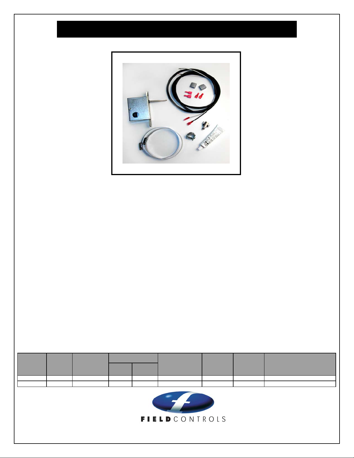
Items Included: 1) High temperature vent limit switch 1) TCA-1 thermocouple junction block (LS-550A)
2) 2-1/2 to 5-1/2 inch hose clamps 1) 6 foot length of 12/2 wire (LS-550A)
1) Tube of high temperature sealant 2) Wire hold down clips (LS-550A)
4) Wiring quick connect terminals (LS-140A) 1) ROMEX connector
Installation of a High temperature vent limit switch is recommended for LP and Natural gas fired power
vented and natural draft water heaters. This device is installed to limit the vent temperature in either
plastic pipe (140
up tanks and/or inadequate venting. Wiring MUST be in accordance with the National Electrical Code and
applicable local codes.
The Field Controls High temperature vent limit switch MUST be installed by a qualified agency in
accordance with the manufacturer’s installation instructions.
The definition of a qualified agency is: any individual, firm, corporation or company which either in person
or through a representative is engaged in, and is responsible for, the installation and operation of gas
appliances, who is experienced in such work, familiar with all the precautions required, and has complied
with the requirements of the authority having jurisdiction.
Before and after adding this safety control on existing appliances, an installation inspection in accordance
with the National Fuel Gas Code 54, Z223.1 Appendix H should be performed and a combustion analysis
is recommended to determine the operating condition of the appliance.
CAUTION: Disconnect Electrical Power When Wiring High tem perature vent limit switch
MODEL P/N
LS-140A 46564100 SILVER 15 A 120 AC 140 AUTOMATIC SPDT PLASTIC VENT APPLICATIONS
LS-550A 46564200 SILVER 15 A 120 AC 550 AUTOMATIC SPDT B-VENT APPLICATIONS
0
F temperature limit) or B vent installations (5500 F temperature limit) caused by scaled
CONTACT
MATERIAL
LOAD RATING
AMPS VOLTS
LIMIT
SETPOINT °F
RESET
SWITCH
TYPE
APPLICATION
2630 Airport Road · Kinston, NC 28504
Phone: 252-522-3031· Fax: 252-522-0214
www.fieldcontrols.com
Page 2
INSTALLATION OF LS-140A SWITCH ON A POWER VENTED WATER HEATERS WITH PLASTIC PIPE
1. Disconnect Electrical Power to the water heater and shut off the gas
supply to the water heater.
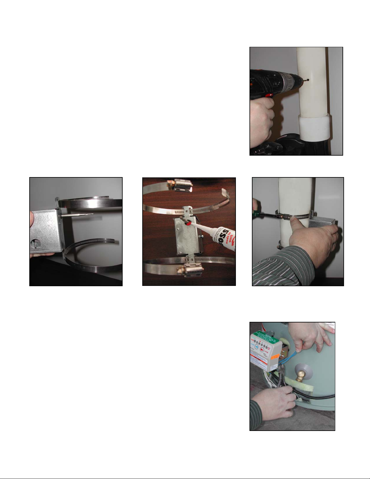
2. Drill a 5/16” diameter hole through the side of the plastic vent pipe at
least 2-inches above the outlet connection on the power venter on the
water heater (See Figure 1).
3. Remove the housing cover of the limit switch.
4. Loosen the two hose clamps and route them through the two mounting
tabs on the ends of the switch housing (See Figure 2).
5. Apply bead of high temperature silicone sealant round the base of the
temperature probe (See Figure 3).
6. Insert the temperature probe into the 5/16” diameter hole in the vent pipe
and secure the switch to the pipe with the two hose clamps (See Figure
4).
Figure 1
Figure 2
Wiring the LS-140A Limit switch
Wire the High temperature vent limit switch in accordance with the National
Electrical Code, manufacturer's recommendations and/or applicable local codes.
THE UNIT MUST BE GROUNDED WHEN WIRED TO ANY 120 VOLT
CONTROLS. Check ground circuit to make certain that the unit has been
properly grounded. The wiring should be protected by an over current circuit
device rated at 15 amperes. Caution must be taken to ensure that the wiring
does not come into contact with any heat source. All line voltage and safety
control circuits, between the vent damper and the appliance, MUST be wired in
accordance with the National Electrical Code for Class I wiring or equivalent
methods.
Figure 3
Figure 4
BEFORE STARTING WIRING, TURN OFF ALL ELECTRICAL POWER
TO THE APPLIANCE AT THE APPLIANCE SERVICE SWITCH OR
CIRCUIT BREAKER!!
1. Locate the wire connection to the solenoid valve on the gas valve.
2. Cut one of the leads to the solenoid valve and attach a female wire
connector to each wire (See Figure 5 and 6).
3. Attach the two male wire connectors to installer supplied wire leads (See Figure 7), connect them to the
Page 2
Figure 5
Page 3

connectors on the solenoid valve and route the wires from the solenoid valve connections to the common terminal
and the normally close (NC) terminal on the LS-140A limit switch (See Figure 8). Also route installers supplied
green grounding wire from the LS-140A limit switch and connect to any convenient grounding surface at the gas
valve.
Figure 6
Figure 7
Figure 8
INSTALLATION OF LS-550A SWITCH ON A NATURAL DRAFT WATER HEATER WITH B-VENT
1. Adjust the thermostat on the water heater gas valve to the pilot position and shut off the gas supply to the water
heater.
2. Drill a 5/16” diameter hole through the connection joint on the end on the B-vent next the draft hood (See Figure
9).
3. Remove the housing cover of the limit switch.
4. Loosen the two hose clamps and route them through the two mounting tabs on the ends of the switch housing
(See Figure 2).
5. Apply bead of high temperature silicone sealant round the base of the temperature probe (See Figure 3).
6. Insert the temperature probe into the 5/16” diameter hole in the vent pipe and secure the switch to the pipe with
the two hose clamps (See Figure 10).
Figure 9
Figure 10
Page 3
Page 4

Wiring the LS-550A Limit switch
Wire the High temperature vent limit switch in accordance with the National Electrical Code, manufacturer's
recommendations and/or applicable local codes. THE UNIT MUST BE GROUNDED WHEN WIRED TO ANY 120 VOLT
CONTROLS. Check ground circuit to make certain that the unit has been properly grounded. The wiring should be
protected by an over current circuit device rated at 15 amperes. Caution must be taken to ensure that the wiring does not
come into contact with any heat source. All line voltage and safety control circuits, between the vent damper and the
appliance, MUST be wired in accordance with the National Electrical Code for Class I wiring or equivalent methods.
BEFORE STARTING WIRING, TURN OFF ALL ELECTRICAL POWER TO THE APPLIANCE AT THE
APPLIANCE SERVICE SWITCH OR CIRCUIT BREAKER!!
30 MILLIVOLT WATER HEATER:
The application requires a TCA-1 Thermal Couple Junction block and a 6 foot length of 12 ga. two (2) wire conductor
CAUTION: Shut off gas supply before working on appliance.
1. Remove thermocouple from gas control valve. (See Figure 11)
2. Thread the TCA-1 junction block into the thermocouple port
and thread the thermocouple into the bottom of the TCA-1
junction block.
3. Connect the 12 ga wire to the two quick connect terminals on
the TCA-1(See Figure 12). Then route the 12 ga wire to the
LS-550 limit switch. Secure the wires to the water heater
enclosure with acceptable hold down tabs, keeping the wires
away from any hot surface area.
Figure 11
4. Connect one 12 ga wire lead to the common terminal
connection on the limit switch and connect the other 12 ga wire
lead to the normally closed (NC) terminal connection on the
limit switch (See Figure 13).
Figure 12
Figure 13
Page 4
P/N 46570600 01/09
 Loading...