

Page 1
HEALTHY HOME SYSTEM
CONTROL Plus
Model: HHSC+
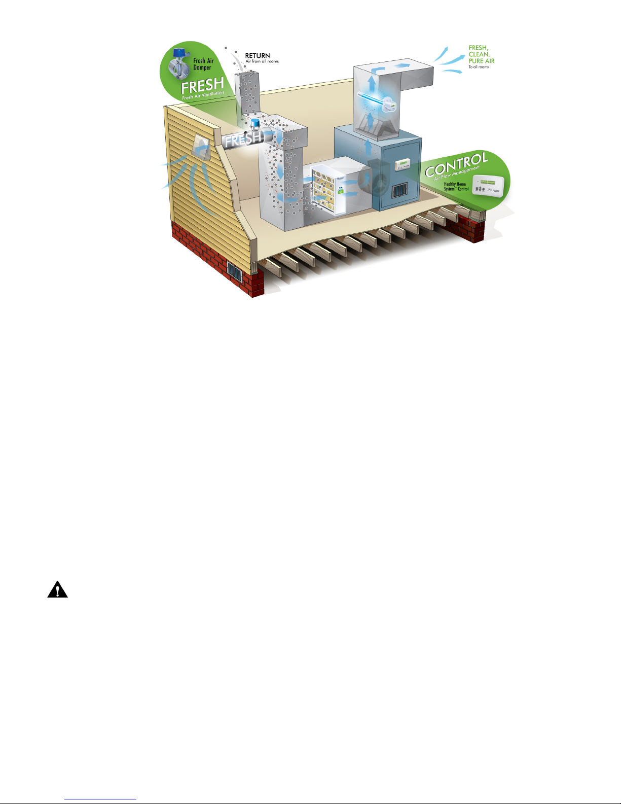
The Field Controls Healthy Home System™ Controller Plus (HHSC+) is designed to work in conjunction with
the forced air HVAC system to periodically introduce fresh air into the home by controlling an FAD Fresh Air
Damper installed in a fresh air duct connected to the HVAC return plenum, and circulate it throughout the
home eectively and eciently, and enables the HVAC system to meet ASHRAE 62.2 and other ventilation
codes and standards.. The HHSC+ is designed to operate continuously year round without user intervention.
The HHSC+ is initially programed by the installer and operates interactively with the HVAC system thermostat.
Certain features are readily accessible by the occupants for customization of the system, to meet their individual
preferences.
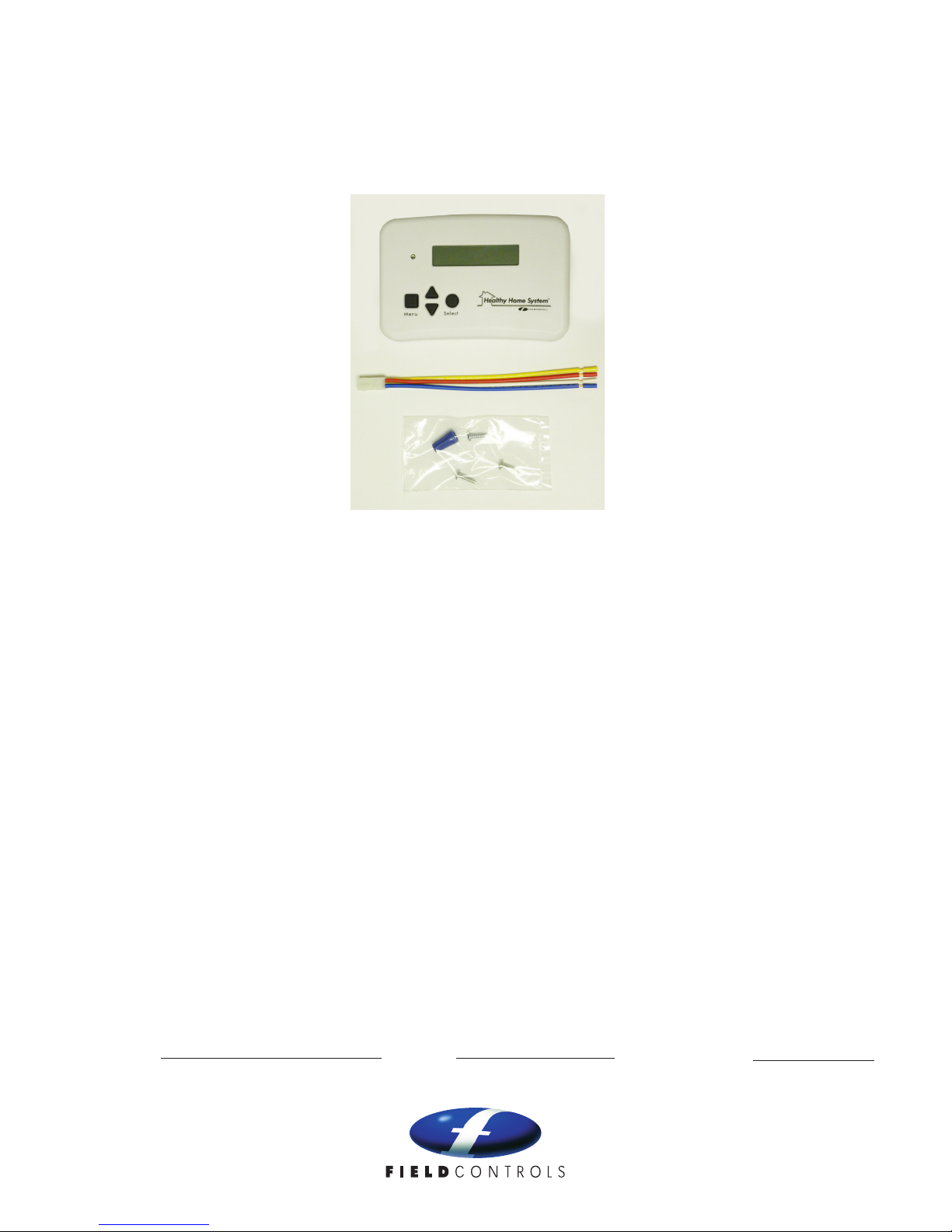
ITEMS INCLUDED IN KIT:
1-HHSC+ Ventilation and Fan Cycling Control
1-Four-wire connector harness for FAD Fresh Air Damper (FAD not included)
1-Installation Hardware
1-Instruction Booklet
READ THESE INSTRUCTIONS CAREFULLY AND COMPLETELY BEFORE PROCEEDING WITH THE INSTALLATION.
This device MUST be installed by a qualied agency in accordance with the manufacturer's installation instructions. The denition of a
qualied agency is: any individual, rm, corporation or company which either in person or through a representative is engaged in, and
is responsible for, the installation and operation of HVAC appliances, who is experienced in such work, familiar with all the precautions
required, and has complied with all the requirements of the authority having jurisdiction.
Installed By: Phone:
Please retain these instructions after installation.
Installation Date:
www.eldcontrols.com
Page 2
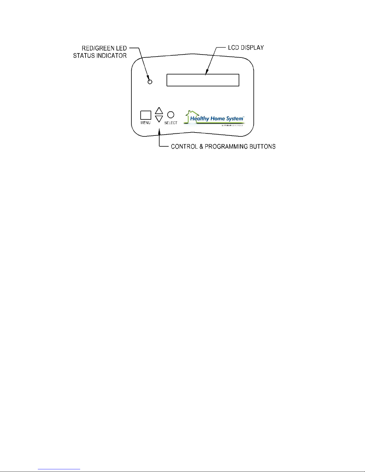
FEATURES
• System Status LED
• User-Programmable Inhibit Mode
• UV lamp replacement reminder
• Air Filter replacement reminder
• Time/Date display
• Automatic Daylight Savings Time correction
• Damper Monitor Feature monitors FAD damper for proper operation
• Remote Activation Terminals: timer, on/o switch, Carbon Monoxide (CO) detector with alarm contacts,
makeup air sensor, multiples having dry contacts
• Auxiliary Output terminals (24 VAC): exhaust fan, etc.
• Powered by system transformer, works in conjunction with 24V thermostat or EIM, no additional transformer
required
• Compatible with any system having accessible 24V R W Y G terminals
page 2
Page 3
INSTALLATION
CHOOSE FAD FRESH AIR DAMPER LOCATION:
The fresh air damper can be located anywhere in the fresh air inlet duct. Minimize the length of the inlet
duct to improve airow and improve system eciency. It is recommended that the damper be as close to
the return air plenum and the HHSC+ as possible, and that the inlet duct connect to the return plenum
upstream of the system lter, and downstream of any duct-mounted sensors.
CHOOSE FRESH AIR INTAKE LOCATION:
ASHRAE recommends that the fresh air intake be located at least 10’ from any source of pollutants, such
as auto exhaust, dryer exhaust, exhaust from any fuel-burning appliance, etc. Avoid installation near odor
sources such as garbage bins or barbecue grills. A minimum of 3’ above ground is recommended to avoid
ingress of leaf litter, grass clippings, etc. Do not use a crawl space, basement, or attic as a source of intake
air. Always be sure to comply with local building code requirements regarding fresh air inlets.
CHOOSE HHSC+ CONTROL LOCATION:
The HHSC+ controller provided with your Fresh Air System can be installed anywhere in your home.
Because the HHSC+ does not require routine adjustment it is generally more eective to mount the
controller as close to the HVAC system and damper as possible.
CAUTIONS
• Before installing the HHSC+, turn o all power to your HVAC system.
• Read and follow all instructions carefully.
• Follow all local electrical codes during installation. All wiring must conform to local and national electrical
codes.
• Use caution when mounting components to surfaces that may have concealed wiring beneath the surface.
page 3
Page 4

INSTALLATION (con’t)
HOW TO INSTALL DAMPER:
The damper may be installed in any position; although it is recommended to install with the motor at the
3 or 9 o’clock position if mounted horizontally. Air may ow through in either direction, although it is
recommended to install with the crimped end as the outlet of the damper. Use care to avoid distorting the
damper housing, and provide adequate support.
HOW TO INSTALL THE CONTROLLER:
HHSC+ OVERVIEW
CAUTION: DISCONNECT POWER TO THE HVAC SYSTEM BEFORE BEGINNING ANY ELECTRICAL
CONNECTIONS OR MODIFICATIONS TO EXISTING WIRING.
1. Unsnap the HHSC+ mounting base (back of unit) from the HHSC+.
2. Route wires through large hole in the mounting base. Hold the base against wall and mark wall through 3
mounting holes.
3. Drill 3 - 1/8-in. pilot holes in wall where marked, or holes for drywall anchors if mounting on drywall.
4. Secure mounting base to wall with 3 screws (provided), making sure all wires extend through hole in
mounting base.
5. Adjust length and routing of each wire to reach proper terminal and connector block on mounting base
with 1/4 in. of extra wire. Strip only 1/8 to 3/16 in. of insulation from each wire to prevent adjacent wires
from shorting together when connected.
6. Connect wires to proper terminals of the connector blocks, use appropriate diagram from Typical Wiring
Diagrams. Both (R) and (C) must be connected for proper operation. Improper wiring or installation may
damage the controller. If using stranded wire, use caution to avoid shorts from stray strands. Check to
make sure wiring is correct before proceeding with installation or turning the unit on.
7. Push any excess wire into wall and against mounting base.
8. Snap HHSC+ onto base making sure pins align with sockets in connectors.
9. Once initially powered the HHSC+ will automatically enter into installer programming mode.
page 4
Page 5
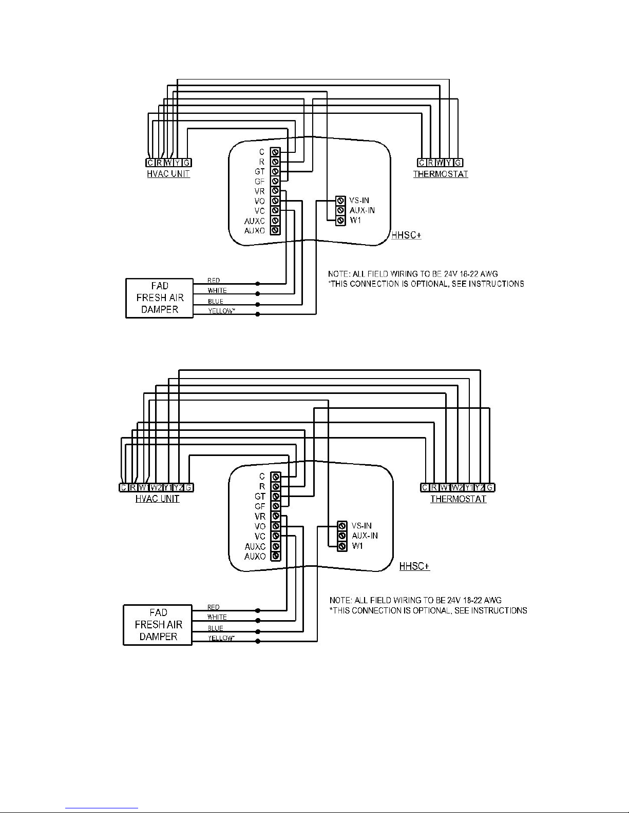
TYPICAL WIRING DIAGRAMS
Figure 1 Single-Stage Heating/Cooling
Figure 2 Multi-Stage Heating/Cooling
page 5
Page 6
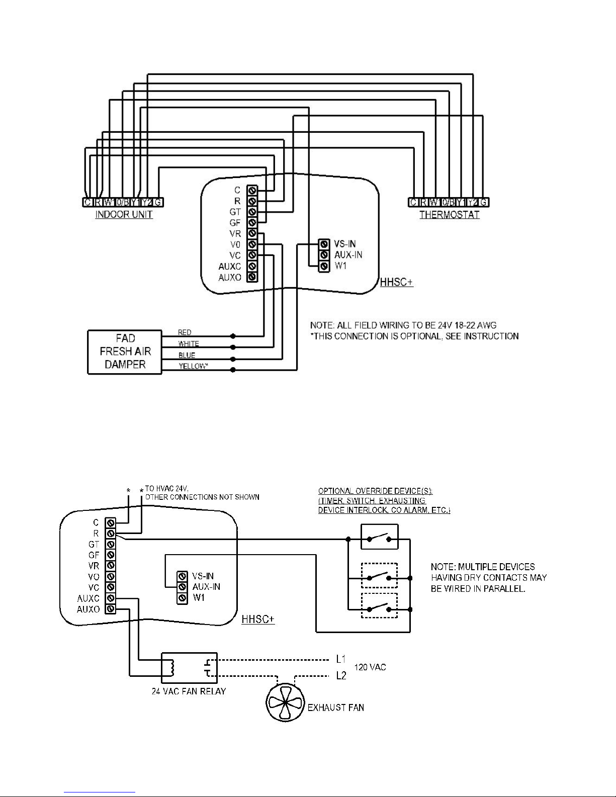
TYPICAL WIRING DIAGRAMS (con’t)
Figure 3 Heat Pump
WIRING TO OPTIONAL EXHAUST FAN AND/OR OPTIONAL REMOTE
OVERRIDE DEVICES
Figure 4 Exhaust Fan & Override Device Control
page 6
Page 7

OPTIONAL EXHAUST FAN CONTROL:
The HHSC+ may optionally control an exhaust fan (not included) using the AUXC and AUXO auxiliary
output terminals (wiring to thermostat and HVAC unit not shown for clarity) on the base. Connect the
terminals to a 24 VAC relay (not included, 1A max. current) to control a 120 VAC exhaust fan. Whenever
ventilation is occurring (the FAD damper is opened), these terminals will be energized and the fan relay
will activate the exhaust fan to work in conjunction with the Healthy Home System to provide balanced
ventilation. At other times, the exhaust fan may be locally controlled by a wall switch or timer wired in
parallel with the relay.
These terminals may also be used as 24 VAC input to control a device having 24 VAC control terminals
(max. 1A current).
OPTIONAL REMOTE OVERRIDE CONTROLS:
The HHSC+ may be remotely controlled by optional override device(s); see the Activation by Remote
(Override) Device(s) section under Operation.
OPTIONAL OUTDOOR THERMOSTAT AND/OR HUMIDISTAT (not included):
The FAD damper blue wire may be wired in series with an outdoor thermostat and/or humidistat, to prevent
ventilation if outdoor conditions are extreme. Note: the Damper Monitor feature must be disabled if this
option is installed; see Damper Monitor feature in Setup.
Figure 5 Outdoor Thermostat/Humidistat
page 7
Page 8

SETUP
NAVIGATING THE MENU
Please refer to the color-coded Menu Map for guidance through the HHSC+ menu structure. Each
colored box on the Map represents a particular menu item window that will appear on the HHSC+ display.
The button colors, shapes, and action arrows in a Map item box correspond to the actions and settings
available in the corresponding display menu item window. For instance, if the available selections in a Map
item box are colored green, then the HHSC+ selection(s) are adjusted or selected by pressing the button(s)
that are colored green in the corresponding Map item box. If an action arrow leads from a box to another
box, the button with the corresponding color will cause the action indicated by the arrow.
Pressing “MENU” (square menu button symbol) either scrolls to the next main menu item without entering
any settings windows beside a main menu item, or typically exits the settings boxes back to the main menu.
Pressing the up or down arrow buttons (up/down arrow symbols) typically adjust the setting(s) available in
that particular menu item window.
Pressing “SELECT” (round select button symbol) typically advances to the next settings window beside a
main menu item, or exits from the last settings window back to the main menu.
A main menu item may have settings that are directly adjustable in the main item window, and/or additional
settings windows that are available under that main menu item, as accessed by pressing the “SELECT”
button.
INSTALLER SETTINGS
The Installer Settings main menu items (orange Map boxes) appear by default upon the rst power-up of the
HHSC+, and at other times by pressing and holding both “MENU” and “SELECT” buttons at the same time for
several seconds. The menu items are:
UV LAMP AND FILTER TIMERS RED MAP BOXES:
The UV lamp timer will cause the HHSC+ status LED to turn red, and display a message reminding the
user to replace UVC germicidal lamp(s) if desired, when the selected replacement period has passed since
the timer was reset. Available selections are 1 year, 2 years, and None (if no UVC lamp systems have been
installed or if no reminder is desired).
The Filter change timer will cause the HHSC+ status LED to turn red, and display a message reminding the
user to replace the HVAC system lter(s) if desired, when the selected replacement period has passed since
the timer was reset. Available selections are 3 months, 6 months, 12 months, and None (if no reminder is
desired).
VENTILATION SETTINGS RED MAP BOXES:
The Cycle Period determines how often the HHSC+ will activate the HVAC fan for ventilation and
recirculation, if no fan activity is called for by the thermostat before a cycle period has ended. A new
cycle will begin every 30, 45, or 60 minutes as selected, or whenever the HVAC fan is de-activated by the
system thermostat. If the system fan is manually set to On at the thermostat, the HHSC+ will automatically
open the vent damper once every cycle period for the amount of time selected as (Ventilation % ÷100) X
Cycle Period. Note: the Cycle Period does not aect the average ventilation rate and may be set to the
occupant’s preference, without changing the average ventilation rate. The average ventilation rate as may
be required to meet ventilation codes is controlled and aected only by the Ventilate % setting.
Ventilate % and Circulate % settings control how long the FAD fresh air vent damper will be open per cycle
period, and how long the HVAC circulation fan will be caused to run by the HHSC+ per cycle period. For
instance, if Ventilate % is set to 33% (factory default), the FAD damper will open for 33% of the cycle period
(example: cycle period is 60 minutes – the FAD will be open for 20 minutes out of 60 minutes, or 0.33 x 60
= 20).
page 8
Page 9

SETTING THE VENTILATION % TO MEET VENTILATION CODES:
EXAMPLE: MEETING ASHRAE 62.2 2010 with given conditions:
• 2000squarefoothome(conditionedspace)with3bedrooms
• 140cfmoffreshairowasmeasuredinthefreshairductwhilesystemisoperating
1. Determine the required constant ventilation ow rate from table: 50 cfm.
2. Measure the actual ow rate through the fresh air duct using a ow hood, anemometer, or Pitot tube
and manometer, with the HVAC fan running on lowest speed and the FAD damper open (temporarily
jumper AUX-IN to R terminal, or activate remote override device if connected): Example: 140 cfm
measured.
3. Calculate the Ventilation %: Divide the constant ow rate from the table by the actual fresh air ow rate
measured and multiply by 100%:
Ventilation % = 50 ÷ 140 x 100% = 36% (rounding up)
For this example, setting the Ventilation % at 36% will ensure ventilation meeting ASHRAE 62.2, regardless
of any other settings, as long as the HHSC+ system is set to on, and the inhibit feature is not active. Setting
Ventilation % to a higher value will raise the ventilation above the minimum as required by ASHRAE 62.2
To meet other ventilation codes, substitute the alternately required constant ventilation rate in cfm from step
1 into the calculation in step 3.
If the actual ow rate in the fresh air duct cannot be directly measured, the following table may be used to
estimate the Ventilate % setting required for adequate ventilation. Note: using these values will not ensure
ventilation meeting any particular code.
page 9
Page 10

HOME OWNER MENUS
CONTRACTOR
SETUP:
PRESS for 5 sec.
CONTRACTOR SETUP
MENU
Ventilation
Parameters
UV Lamp + Filter
Timers
Damper Mon itor:
Disabled (Automat ic)
DAYLIGH T SAVING S:
Enabled (Disabled)
System Mode:
System ON (OFF)
Inhibit Mode:
Disable E na ble
System Clock
12:34PM 03/10/13
Replace UV Lamp Int erval:
1YR, 2YR, NONE
UV La mp ( Re maining) Days
Reset Timer ?
NO (YES)
Replace Filter Mon ths:
3, 6, 12, NONE
Filter: (Remaining) Days
Reset Timer ? NO (YE S)
Fan Cycl e Period
Cycle Period
30, 45, 60 MI NU TES
SET CYCLE PERIOD
30, 45, 60 MINUTES
10:34AM 03/10/13
SET HOUR:
10:45AM 03/10/13
SET MINUTES:
10:45AM 04/10/13
SET MONTH:
10:45AM 04/23/13
SET DAY:
10:45AM 04/23/13
SET YEAR:
Inhibit Start
Hour: 10:00P M
Inhibit Start
Minutes: 10: 35PM
System Inhibit
duration: 8
> Ventilate: 33%
Circulate:
33%
Menu = Continue
Select = SAVE/EXIT
12:00 PM 1/2 7/ 13
FAN ON VENT ON
HOME SCREEN
Damper Mon itor:
Testing Damper
Pass = Con firmed op en
Fail = Dis abled
page 10
Page 11

NO (YES)
Replace Filter Mon ths:
3, 6, 12, NONE
Filter: (Remaining) Days
Reset Timer ? NO (YE S)
10:45AM 04/10/13
SET MONTH:
10:45AM 04/23/13
SET DAY:
10:45AM 04/23/13
SET YEAR:
System Inhibit
duration: 8
33%
MENU MAP
page 11
Page 12

Circulate % may be set equal to or greater than the Ventilate %, to cause the HVAC fan to run longer per
cycle, for extra circulation, ltration, and UVC treatment if desired, or if the HHSC is used for circulation
only. For instance, if Ventilate % is set to 33% and Circulate % is set to 50%, with the cycle period set to 30
minutes, every thirty minutes the HHSC+ will activate the HVAC fan, open the FAD damper for 10 minutes,
and continue to run the fan for another 5 minutes (.33 x 30 = 10, .50 x 30 = 15) if the thermostat does not
cause the fan to run during the period.
Circulate % may not be set less than Ventilate %, because the HVAC fan must operate when the FAD
damper is commanded to be open by the HHSC+. The Circulate % setting will automatically “follow” the
Ventilate % setting if it is adjusted higher, but will not “follow” it lower.
DAMPER MONITOR
The HHSC+ can continuously monitor the FAD fresh air damper for proper operation, if the feature is
enabled and the yellow wire from the damper pigtail (included) is connected to terminal VS-IN on the
HHSC+ (see Figures 1,2, 3). If enabled and the HHSC+ repeatedly detects a malfunction of the damper,
the status LED will turn to red, and the display will indicate that a damper malfunction has been detected.
NOTE: this feature is optional and may be disabled if desired. If the yellow pigtail wire is not connected to
the HHSC+, the HHSC+ will automatically disable the feature.
If this feature is to be enabled, ensure that the FAD damper pigtail’s yellow wire is connected to terminal VSIN, and select “Automatic” in the Damper Monitor menu item window. The HHSC+ will then automatically
test the damper and its connection. If the damper responds properly, the display will indicate that the
damper is detected and the Damper Monitor feature will be enabled. If the damper does not respond
properly or the yellow wire is not connected, the HHSC+ will automatically disable the feature.
This feature may also be disabled manually at any time by selecting the Damper Monitor menu item
window and selecting “Disabled”, even if the yellow pigtail wire is connected. If an outdoor thermostat or
other device is used to prohibit fresh air ventilation when extreme outdoor conditions exist (wired in series
between the FAD blue wire and terminal VO, see (Figure 6), the feature must be disabled to prohibit false
malfunction detection.
Daylight Savings Time mode: If this feature is enabled, the HHSC+ will automatically adjust its clock time
by changing the time by one hour on the specied dates for transitioning to or from Daylight Savings time
to Standard time, regardless of the time zone. This feature is important for keeping the Inhibit Mode time
schedule correct (see Inhibit Mode feature section), without any changes needed by the user. This feature
may be disabled for those areas that do not observe Daylight Savings Time changes.
page 12
Page 13

HOMEOWNER (USER) SETTINGS
The Homeowner Menu items (dark green Map item boxes) are directly available under normal operation, and
are accessed simply by pressing the MENU button while at the home screen window, or from the Daylight
Savings menu window in the Contractor Setup menu. It is not necessary to press MENU and SELECT to enter
the Homeowner Settings menus. The Homeowner Menu items are intended to be the main features of interest
by the occupants, while the Contractor Setup Menu items are intended to be accessed only by those installing the
HHSC+.
SYSTEM ON/OFF
Setting this parameter to “O” will terminate all input and output functions of the HHSC+, except for the
time/date display, and the status LED will not be lit. The HVAC system will continue to operate normally,
with complete control of the system by the thermostat allowed, including manual fan on/auto control at the
thermostat. The HHSC+ will continue to be internally powered, in order to maintain the time, date, and UV
and lter replacement timers. All HHSC+ settings are retained in “ash” memory; no external or internal
battery power is required to maintain the HHSC+ settings. When the HHSC+ System is set back to “On”,
the HHSC+ will resume all normal functions with all settings as they were before the HHSC+ was turned o.
CLOCK/CALENDAR SET
Press SELECT to set the clock hour (AM and PM), again to set the minutes, and so forth to set the month,
day, and year. While it is not necessary for the date to be correct for maintenance of the UV and Filter
timers, setting the correct date will result in the automatic Daylight Savings time corrections (if enabled)
to occur on the correct dates. This will preserve proper timing of the Inhibit Mode timing (if enabled)
throughout the year, automatically.
INHIBIT MODE
This feature allows the occupants to set a daily period in which the HHSC+ will be prohibited from causing
the HVAC system fan to run according to the programmed Ventilate, Circulate, and Cycle Period settings,
while allowing full control of the HVAC system solely by the thermostat. As a result, the average rates of
circulation and fresh air ventilation may be reduced during this period.
While use of this feature may violate some ventilation code requirements, the fresh air rate actually required
for adequate ventilation is typically greatly reduced during this time, such as when the occupants are resting
or absent and no activity is occurring in the house.
To set and activate the Inhibit Mode, press the SELECT button to enter the programming windows. First set
the hour and minute for the time of day/night that the inhibit period is desired to begin. Press SELECT again
to set the duration (in hours) of time for which the HHSC+ is desired to be inhibited from activating the
HVAC fan. For instance, if the inhibit period is desired to be from 10:30 PM to 6:30 AM, set “Inhibit Start”
to 10:30 PM, and “System Inhibit Duration” to 8 hours.
If “System Inhibit Duration” is set to zero (factory default), Inhibit Mode will be automatically disabled.
FAN CYCLE PERIOD
The Fan Cycle Period menu item allows the occupant(s) to select the desired cycle period, or how often the
HHSC+ will activate the system by itself, as when the thermostat may be satised for long periods. The
available selections are 30, 45, and 60 minutes. This feature is also found in the contractor setup menu
item as Cycle Period; changing the cycle period in either menu item will have the same eect.
NOTE: Changing the Fan Cycle Period will not aect the average fresh air ventilation rate, which is solely
controlled by the Ventilation % setting. It may be freely changed without altering the eective ventilation as
required to meet a given ventilation standard.
page 13
Page 14

SAVING THE SETUP
While in the Menu = Continue/Select = Save & Exit window, press SELECT to save the setup settings, exit
to the normal operation display window and begin normal operation, or MENU to continue with viewing the
available menu items and settings.
If no buttons are pushed for three minutes, any changes to settings will be automatically saved and the
HHSC+ will return to normal operation with any changes to settings taking eect immediately.
OPERATION
NORMAL OPERATION DISPLAY AND LED STATUS
Under normal operation, the status LED will glow steady green and the HHSC+ display will show the current
time and date on the upper display line. On the lower display line, “FAN ON” will be displayed if the HVAC
fan is on (from either thermostat command or HHSC+ program), and “VENT ON” if the FAD vent damper
is open.
The status LED will glow steady red, and the display will show an alert message, if action is required for
service or maintenance:
• UVlampreplacement:theselectedperiodforreplacingUVCgermicidallamp(s)hasexpired.
Replace the lamp(s) and reset the timer by following the instruction on the display.
• HVAClterreplacement:theselectedperiodforreplacingtheHVACsystemlter(s)hasexpired.
Replace the lter(s) and reset the timer by following the instruction on the display.
• DamperMalfunction:theHHSC+hasdetectedanFADfreshairdampermalfunction(ifenabled).
Service is required to correct the malfunction; the alert will automatically reset when the malfunction is
corrected, or the Damper Monitor feature is disabled.
• Theinternalbackupbatteryhasbecomeweakandisinneedofreplacement.
INDEPENDENT OPERATION
The HHSC+ will command the HVAC fan to operate periodically for a specic length of time, as governed
by the chosen Fan Cycle Period and Circulate % settings, for a length of time (in minutes) equal to
Fan On time = Fan Cycle Period setting (minutes) X Circulate % ÷ 100
Also, the HHSC+ will command the FAD vent damper to open, and the Auxiliary Output terminals will be
energized (24 VAC), at the beginning of each fan cycle, for a length of time (in minutes) equal to
Vent On time = Fan Cycle Period setting (minutes) X Ventilate % ÷ 100
If the Damper Monitor feature is enabled, the Auxiliary Output terminals will not energize until the FAD
damper opens fully and communicates back to the HHSC+ by energizing the VS-In terminal via the FAD
pigtail’s yellow wire; otherwise, the Auxiliary Output will be energized immediately. The FAD damper and
Auxiliary Output will not be activated for a longer time than the HVAC fan will be commanded to run, but
they may be activated for a shorter time.
At the expiration of the Fan On time, the HHSC+ will end the commands to the FAD damper, the HVAC
fan, and the Auxiliary Output. The HHSC+ will then remain idle for the remainder of the Fan Cycle Period,
when it will begin a new cycle, or the system thermostat calls for action, as described below.
page 14
Page 15

ACTIVATION BY THERMOSTAT
The HHSC+ monitors the activity of the thermostat and performs operations as described here. If the
thermostat issues a demand for heating or cooling, or the HVAC fan is manually switched on, before an
HHSC Fan On or Fan Cycle Period time expires (see Independent Operation above), the HHSC+ will
immediately begin a new Fan Cycle period. The HHSC+ will then command the FAD vent damper to open,
and the Auxiliary Output terminals will be appropriately energized, for the Fan On and Vent On times as
stated above. The HVAC fan will also be commanded to run by the HHSC+ if either a cooling demand
occurs, or if the fan is manually switched on at the thermostat.
NOTE: The HHSC+ will not give a command to run the HVAC fan if a demand for heating only occurs.
The HVAC system will operate the fan independently when this occurs. This is also true when there is
a demand for cooling, but the HHSC+ merely transmits the fan on command which is issued by the
thermostat.
If the thermostat becomes satised and terminates the command for heating or cooling, or the fan is
manually switched to O or Auto while there is no current demand for heating or cooling, the HHSC Fan
ON and Vent On times will be cut o, and the HHSC+ will terminate the commands to the FAD damper,
the HVAC fan, and the Auxiliary Output. The HHSC+ will then remain idle for the remainder of the Fan
Cycle Period, when it will begin a new cycle, or the system thermostat calls for new HVAC action.
ACTIVATION BY REMOTE OVERRIDE DEVICES
Remote device(s) having dry contacts, such as simple wall switches, timers, CO alarm contacts, pressure
switches etc. may be used for remote activation of the HHSC+ ventilation system. Multiple such devices
may be connected to the AUX-IN and R terminals in parallel (see Fig. 4); if any of these devices complete
an electrical connection between R and AUX-IN, the HHSC+ will activate the HVAC fan, open the FAD
damper, and activate the Auxiliary Out terminals, for as long as any of the remote devices are closed.
NOTE: Do not directly connect any devices having solely electronic means of switching electrical current
(transistor or triac switching), such as many current sensing relays; electrical leakage through such devices
may cause improper operation of the system and may damage the HHSC+ and/or other remote devices. If
such a device is to be used, install an isolation relay between the HHSC+ and the device.
POWER OUTAGE
If a power outage occurs, the HHSC+ will resume normal operation after about 15 seconds after power is
restored, with all settings as they were prior to the outage, and will display the correct time and date. The
display and LED will not show or be illuminated, but the internal backup battery will continue to maintain the
time, date, and lter and UV lamp replacement timers; no corrections are required. Battery life is in excess
of one year under such conditions.
page 15
Page 16

OPERATION
LED STATUS INDICATOR LIGHT
A steady green light indicates that the Healthy Home System is operating properly. A steady red light
indicates action should be taken; one or more messages will be displayed on the display, giving instructions
for corrective action(s), such as HVAC lter life expiration, UV lamp life expiration, or a fault having been
detected with the FAD damper (if enabled); see Normal Operation Display and LED Status section. The
display will also indicate how to reset the LED and display after such an event.
PROBLEM: BLANK DISPLAY ON THE HHC+
SOLUTION CHECK
1. Make sure controller cover is rmly seated in the base; press rmly on the HHSC+ to ensure contact of pins
2. The furnace has power
3. The thermostat is operational
4. The furnace will call for heat from the thermostat
5. The fan operates with a fan only signal from the thermostat
6. Conrm the furnace is providing 24 VAC to the HHSC+
7. Verify wiring conforms to wiring diagrams and connections are dry and tight.
PROBLEM: HHSC+ TURNS FURNACE FAN ON AND OFF, BUT THE MOTORIZED DAMPER DOES NOT
CYCLE
SOLUTION CHECK
1. Verify that the mode selector switch on the FAD damper motor is in the “Auto” position
2. Verify that the HHSC+ is providing a 24 VAC signal to the FAD damper
3. Verify that the FAD damper is operational by disconnecting from the HHSC and applying 24VAC to blue
and white wires (open), and then red and white (close).
4. Verify continuity in the wiring between the damper and the HHSC+.
PROBLEM: A/C TURNS ON DURING FAN CYCLING CALLS
SOLUTION CHECK
1. Verify wiring conforms to appropriate wiring diagram.
2. Verify the GT and GF wires are properly connected. The G wire normally running between the thermostat
and the HVAC equipment needs to be interrupted by the HHSC+. Do not run the G wire in parallel GT
and/or GF terminals. The HHSC+ should not back-feed power to the thermostat from the GT terminal by
internal energization.
page 16
Page 17

REPLACEMENT PARTS
Pig Tail Harness P/N 46633900
Internal Battery Available at local retail outlets (See Battery Specication for replacement information)
SPECIFICATIONS
HHSC+
Electrical
Wiring Requirements 18-22 AWG, 24 VAC min
Operating Voltage 20-30 VAC
Maximum Operating Current 1A per input/output circuit, 3A max. Combined
Thermal
Operating Ambient Temperature Range 32°F to 120°F (0°C to 49°C)
Operating Humidity Range 5 to 90% RH (non-condensing)
Shipping Temperature Range 14°F to 140°F (-10°C to 60°C)
FRESH AIR DAMPER
Electrical
Minimum Wiring Requirements 18AWG, 24 VAC
Maximum Voltage 30 VAC
Maximum Operating Current 0.1 Amps
Power Draw Requirement 3W at 24VAC when opening or closing
Timing 15 sec Power OPEN, 15 sec Power CLOSE
Thermal
Operating Ambient Temperature Range 32°F to 150°F (0°C to 66°C)
Operating Humidity Range 5 to 90% RH (non-condensing)
Shipping Temperature Range -20°F to 160°F (-29°C to 71°C)
page 17
Page 18

page 18
Page 19

page 19
Page 20

Warranty
For warranty information about this or any Field Controls product, visit:
www.eldcontrols.com/warranty
© Field Controls, LLC P/N 46633800 Rev. A 07/15
Phone:252.522.3031•Fax:252.522.0214
www.fieldcontrols.com
 Loading...