

Page 1
GAS SPILLAGE SENSING KIT
Model: GSK-160A
(with automatic reset)
Installation of a spillage SAFETY Switch is recommended for
LP and Natural gas fired systems with gas barometric draft
controls. This device is intended for installation on a
double-acting barometric draft control (such as the Field
Controls model MG-1) that is installed in the venting
system of an 80+ efficiency rated, fan-assisted gas-fired
appliance. It is designed to detect flue gas spillage caused by a
blocked flue system and/or inadequate draft. This device MUST
be installed by a qualified installer in accordance with the
manufacturer's installation instructions. Wiring MUST be in
accordance with the National Electrical Code and applicable
local codes.
Before and after adding this safety control on existing
appliances, an installation inspection in accordance with the
National Fuel Gas Code 54, Z223.1 Appendix H should be
performed and a combustion analysis is recommended to
determine the operating condition of the appliance.
CAUTION: Disconnect Electrical Power When Wiring Spillage
Switch
2630 Airport Road · Kinston, NC 28504
Phone: 252-522-3031· Fax: 252-522-0214
www.fieldcontrols.com
Page 2
OPERATION:
The GSK-160A is a normally closed single-pole, single throw (SPST)
thermally-activated switch that is intended to be wired in series with the
burner control safety circuit of an 80+ efficiency-rated, fan-assisted, gasfired appliance. When subjected to temperatures above approximately
160°F, the switch will open, interrupting the safety circuit, thereby
preventing the burner from firing. When allowed to cool, the switch will
automatically reset, allowing the burner to fire. Activation of the GSK switch
may cause burner lockout on some appliances.
INSTALLATION ON DRAFT CONTROLS:
NOTE: GSK style switches are designed for mounting on draft control
models 4” MG1 through 9” MG1. Larger size draft controls required the FTS
series switches.
U
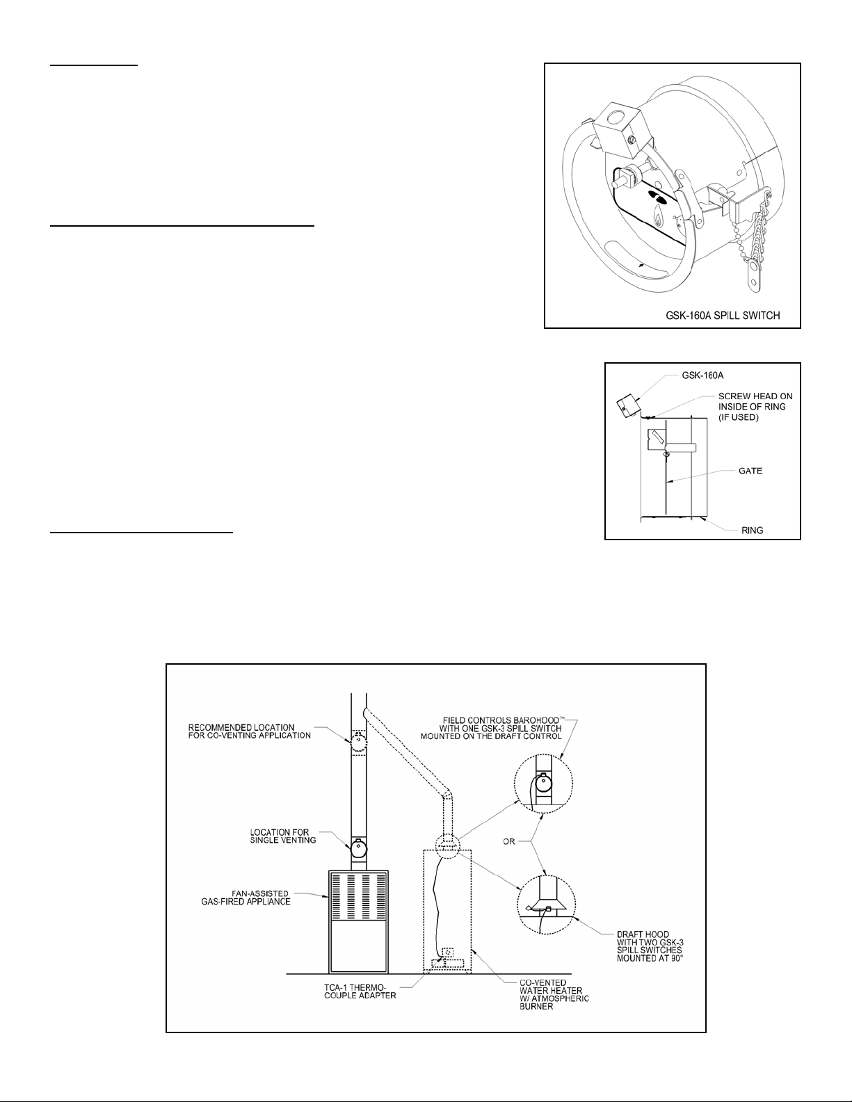
NIT WITH MG1 DRAFT CONTROL SUPPLIED WITH GSK IN A KIT:
1. Mount the switch onto the threaded stud on the top front of the
MG1, using the supplied 8-32 locking nut.
Figure 1
2. Swing the gate in and out to verify smooth operation through the range of
operation.
U
NIT WITH DRAFT CONTROL SUPPLIED SEPARATELY:
1. Mount the switch with the supplied #5-40 machine screw and nut on the top
front of the MG1. (Note, the head of the screw is to be on the inside of the
ring. (See Figure 2)
2. Swing the gate in and out to verify smooth operation through the range of
operation.
INSTALLATION LOCATION:
For single-appliance venting applications, install the draft control with GSK-160A
directly above the appliance as shown in Figure 3, unless otherwise instructed by the
Figure 2
appliance manufacturer. For co-venting applications with an atmospheric-burne r-equipped appliance (such as a water
heater), install the draft control with GSK-160A immediately below the tee or wye fitting, as shown by the dashed lines in
the figure, to help prevent spillage at the water heater. A Field Controls Barohood
TM
with one GSK-3 mounted
(recommended) or two GSK-3 spill switches mounted on the draft hood (available in kit SSK-1), wired into the
thermocouple circuit (use one TCA-1 for either method) is recomme nded for additional safety.
Figure 3
Page 2
Page 3

WIRING:
CAUTION: When wiring the spillage switch into the burner control circuit route the wiring and secure away from
any hot surface. Shut off all electrical power and gas supply to the appliance before working with any electrical
connections.
CAUTION: Never wire to the 24V GND terminal.
Wire the spill switch in series with the burner fan-proving air pressure switch(es) as shown in Figure 4.
WARNING: All field wiring must be in accordance with appliance manufacturer’s recommendations and
all applicable local and national electrical codes.
Figure 4
SYSTEM CHECK-OUT PROCEDURE FOR GAS SPILLAGE SWITCH CONTROL
1. Disconnect electrical power to the appliance.
2. Shut off gas supply to appliance(s).
3. Block the flue pipe above the draft control, draft hood or draft diverter.
4. Re-establish gas supply to appliance and re-light pilot (if required).
5. Adjust thermostat to call for heat.
6. Flue gases should be spilling from draft control hood. Allow approximately 2 minutes for the system to back up and the
GSK to trip, shutting the burner off.
7. Disconnect electrical power, shut off the gas supply, and remove the blockage from the vent pipe after allowing the vent
to cool.
8. The GSK switch should reset a few minutes after tripping, and allow normal operation of the appliance. If the burner
control has locked out, reset for normal operation.
CAUTION: If for any reason the system has shut down during normal operation, the cause of the system failure should be
investigated and corrected before resetting the safety switch and relighting the pilot.
Page 3
Page 4

Page 4
P/N 46561800 07/08
 Loading...