

Page 1
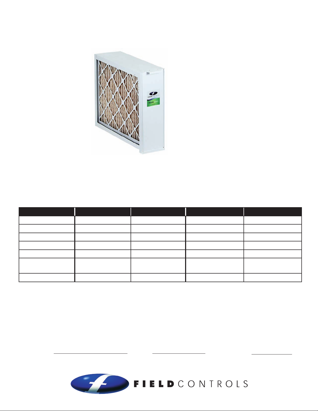
MEDIA AIR CLEANER
Models: FC8-1400, FC11-1400, FC8-2000, FC11-2000
ITEMS INCLUDED IN KIT:
1- Cabinet
1- Media Filter
1- Installation Instruction
Manual
GENERAL SYSTEM INFORMATION
Field Controls high efficiency series of media air cleaners are designed for installation into heating, ventilation,
air conditioning (HVAC) systems to reduce the amount of airborne particulate (1.0 micron and larger) including
pollen, dust and dander promoting better indoor air quality. The media air cleaner should be installed in
the return air system duct, such that all of the circulated air passes through the filter. For maximum filtering
performance, the air circulation fan should operate continuously.
Model FC8 - 1400 FC11 - 1400 FC8 - 2000 FC11 - 2000
Nominal filter size
Air flow range
MERV rating
Filter Replacement P/N
Cabinet dimensions
Cabinet opening
dimensions
UL filter media listing
16" x 25" x 5" 16" x 25" x 5" 20" X 25" X 5" 20" x 25" x 5"
600–1400 CFM 600–1400 CFM 600–2000 CFM 600–2000 CFM
8 11 8 11
46585900 46568500 46586000 46568600
16 -1⁄4" x 24-7⁄8" x 7-1⁄8" 16 -1⁄4" x 24-7⁄8" x 7-1⁄8" 20-1⁄4 " x 24-7⁄8" x 7-1⁄8" 20-1⁄4 " x 24-7⁄8" x 7-1⁄8"
13-7⁄8" x 22-1⁄2" 13-7⁄8" x 22-1⁄2" 17-7⁄8" x 22-1⁄2" 17-7⁄8" x 22-1⁄2"
Class 2 Class 2 Class 2 Class 2
NOTE: FOR OPTIMUM PERFORMANCE, REPLACE THE MEDIA FILTER EVERY 6 TO 12 MONTHS.
READ THESE INSTRUCTIONS CAREFULLY AND COMPLETELY BEFORE PROCEEDING WITH THE INSTALLATION.
This device MUST be installed by a qualified agency in accordance with the manufacturer's installation instructions. The definition of
a qualified agency is: any individual, firm, corporation or company which either in person or through a representative is engaged
in, and is responsible for, the installation and operation of HVAC appliances, who is experienced in such work, familiar with all the
precautions required, and has complied with all the requirements of the authority having jurisdiction.
Please retain these instructions after installation.
Installed By: Phone:
Installation Date:
www.fieldcontrols.com
Page 2
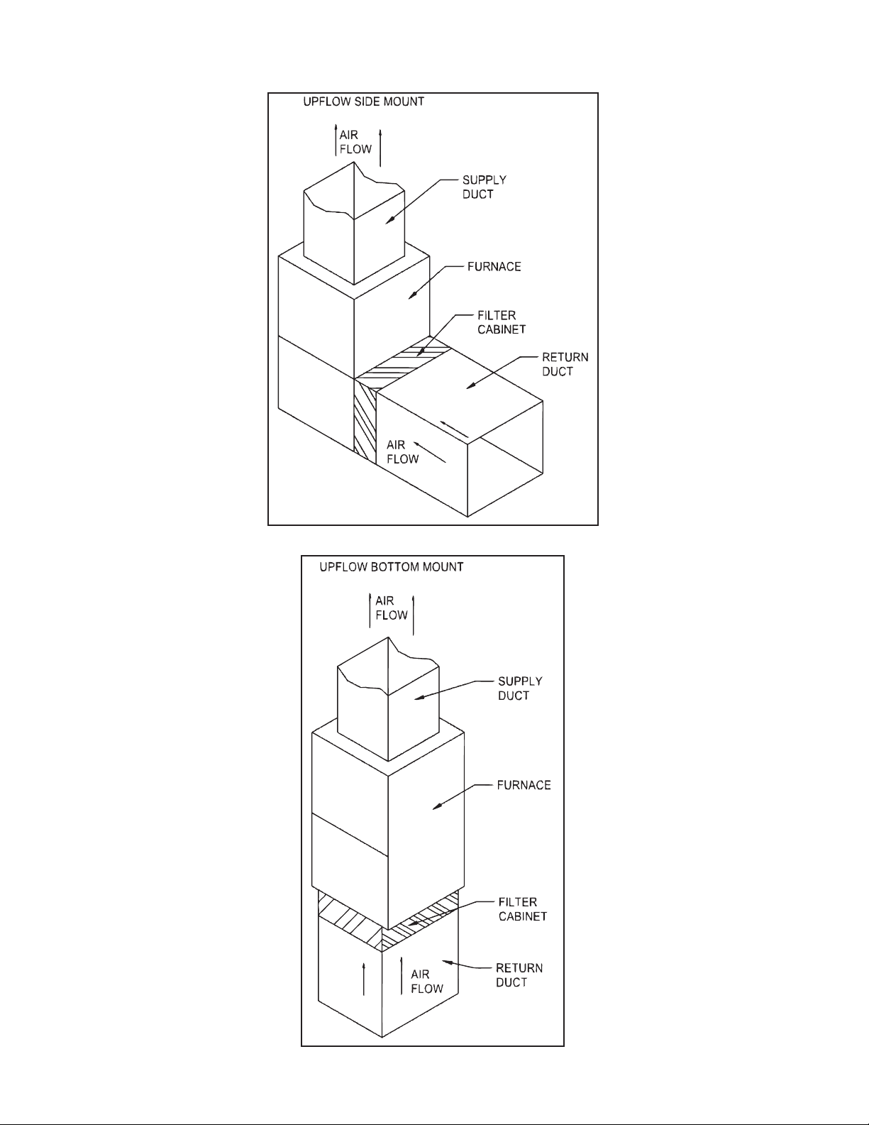
MOUNTING OPTIONS
Figure 1
page 2
Figure 2
Page 3
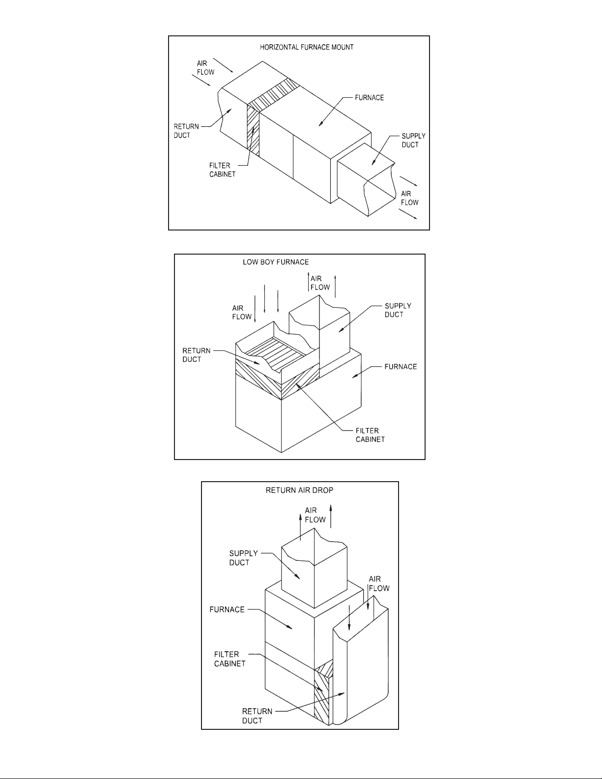
Figure 3
Figure 4
page 3
Figure 5
Page 4

CAUTION
Before installing a media filter into the HVAC system, the Qualified Agency must consider the additional pressure
drop being added to the HVAC system.
1. The filter must be installed on the return side of the HVAC system, between the return air duct and the intake
of the system blower. NEVER install on the supply side of the HVAC system.
2. The filter access panel MUST be installed where there is at least 26” in front of it. This allows clearance for
the replacement of the media filter.
3. Some installations may require a duct transition. Transitions may be needed to reduce pressure drop
and maintain appliance efficiency. The appliance must operate within the manufacturer’s recommended
temperature and pressure drop requirements.
4. Check the flow capacity and pressure drop (Figure 6) to determine the filter is properly sized.
page 4
Figure 6
Page 5

INSTALL ATION
WARNING: Always shut off the electrical power supply before working on the appliance.
1. Refer to the typical mounting positions (Figures 1 to 5) for proper placement of the filter cabinet.
2. Remove the metal filter cabinet from the carton and plastic bag.
3. Remove the access panel door and pull the media filter (in plastic bag) out of the cabinet. DO NOT install the
media filter with the plastic bag around it.
4. Position cabinet so access panel is available for easy media filter replacement The access panel MUST
be accessible to remove and replace the media filter. (NOTE: Minimum of twenty-six (26) inches for front
clearance).
5. Position the filter cabinet onto return air side of the appliance (Figures 1 to 5). Duct transitions may be
required to properly mount the filter cabinet.
6. When the filter cabinet is mounted directly to the appliance or existing duct, mark the inside opening of the
filter cabinet and all 12 mounting screw locations.
1
7. Drill the marked mounting holes with a
⁄8" diameter drill bit. Remove the marked filter opening with metal
cutting shears or equivalent.
1
8. Attach filter cabinet to the appliance or duct work using #8 X
⁄2" long sheet metal screws or pop rivets. Seal
the housing connections with aluminum duct tape or equivalent.
9. Remove media filter from the plastic bag and discard the plastic bag. TIP: Write the installation date on filter
next to directional arrow for future filter replacement reference. The media filter MUST be installed WITHOUT
the plastic bag.
10. Install media filter into the filter cabinet.
11. Install the filter cabinet access panel.
12. Place appliance back into service. Appliance must operate within the appliance manufacturer's
recommended temperature and pressure drop requirements.
page 5
Page 6

MAINTENANCE
The media filter MUST be replaced periodically. The reason is to maintain appliance operating efficiency by
minimizing pressure drop through the HVAC system. The frequency of filter media replacement depends on
the operational environment. The need for replacement is easily determined by a visual inspection. NOTE: For
optimum performance, replace the media filter every 6 to 12 months.
CABINET DIMENSIONS
Model
1400
2000
A B C
Duct Opening
D E
7 1⁄8" 24 7⁄8" 16 1⁄4" 22 1⁄2" 13 7⁄8"
7 1⁄8" 24 7⁄8" 20 1⁄4" 22 1⁄2" 17 7⁄8"
page 6
Figure 7
Page 7

MEDIA FILTER REPLACEMENT PROCEDURE
1. Turn off electrical power to the HVAC system.
2. Remove the filter cabinet access panel. NOTE: “AIR FLOW” directional arrow, located on existing media filter
(Figure 7).
3. Remove the existing filter media.
4. Remove the new media filter from the plastic bag. TIP: Re-use plastic bag to discard the used media filter.
5. Check media filter directional arrow (g)! The directional arrow MUST point in the direction of air flow.
TIP: Write the installation date on media filter next to directional arrow for future filter replacement reference.
6. Install the new media filter.
7. Install the filter cabinet access panel.
8. Turn on electrical power to the HVAC system.
REPLACEMENT PARTS LIST
AIR CLEANER MODEL
REPLACEMENT
FILTER SIzE
REPLACEMENT FILTER
PART NUMBER
NUMBER OF FILTERS
FC8 - 1400 16" x 25" x 5" 46585900 3
FC8 - 2000 20" x 25" x 5" 46586000 3
FC11 - 1400 16" x 25" x 5" 46568500 3
FC11 - 2000 20" x 25" x 5" 46568600 3
PER CARTON
page 7
Page 8

LIMITED WARRANTY
Field Controls, LLC (“Company”) warrants that its products shall be free from defects in material and workmanship
under normal use for the limited period indicated, from the date of manufacture, subject to the provisions 1-8 below.
Eighteen (18) months
All Field Controls Products (except for those listed below as 5 years or 90 days).
Five (5) years
Field Controls Direct Vent Systems (FDVS), Field Oil Vent Kits (FOVP), and ComboVents (CV).
Field Controls warrants that the products listed below shall be free from defects in material and workmanship under
normal use for the limited period indicated, from the date of purchase by the consumer, subject to the provisions
1-8 below.
Ninety (90) days
UV lamps/bulbs
Provisions:
1. During the limited warranty period, Company, or its authorized service representative, will repair or replace, at Company’s
option, without charge, a defective Product. Product that is repaired may be repaired with new or refurbished replacement
parts. Product that is replaced may be replaced with a new or refurbished product of the same or similar design. Company
will return repaired or replacement Product to customer in working condition. Labor charges are not covered as part of the
limited warranty.
2. With regard to UV lamps/bulbs, customer shall be required to include a "valid proof of purchase" (sales receipt) identifying
the Product purchased (Product model or accurate date code information) and the date the Product(s) was purchased.
3. Product whose warranty/quality stickers, Product serial number plates or electronic serial numbers have been removed,
altered or rendered illegible shall not be covered under the limited warranty.
4. Defective Product must be returned to Company, postage prepaid.
5. IN NO EVENT SHALL COMPANY BE LIABLE FOR ANY INDIRECT, SPECIAL, INCIDENTAL, CONSEQUENTIAL, OR SIMILAR
DAMAGES (INCLUDING, BUT NOT LIMITED TO, LOST PROFITS OR REVENUE, INABILITY TO USE PRODUCT, OR OTHER
ASSOCIATED EQUIPMENT, THE COST OF SUBSTITUTE EQUIPMENT, AND CLAIMS BY THIRD PARTIES) RESULTING FROM
THE USE OF PRODUCT. Some states do not allow the exclusion or limitation of incidental or consequential damages, so the
above limitation or exclusion may not apply to you.
6. THIS WARRANTY AND REMEDIES ARE EXCLUSIVE AND IN LIEU OF ALL OTHER WARRANTIES, REMEDIES AND
CONDITIONS, WHETHER ORAL, WRITTEN, EXPRESS, STATUTORY OR IMPLIED. TO THE EXTENT PERMITTED BY LAW,
COMPANY DISCLAIMS ALL IMPLIED AND STATUTORY WARRANTIES, INCLUDING WARRANTIES OF MERCHANTABILITY
AND FITNESS FOR A PARTICULAR PURPOSE.
7. Company makes no warranty of any kind in regard to other manufacturer’s products distributed by Company. Company will
pass on all warranties made by the manufacturer and where possible, will expedite the claim on behalf of the customer, but
ultimately, responsibility for disposition of the warranty claim lies with the manufacturer.
8. Product that has been subjected to misuse, accident, shipping or other physical damage, improper installation or application,
abnormal operation or handling, neglect, fire, water or other liquid intrusion are not covered by the warranty.
Phone: 252.522.3031 • Fax: 252.522.0214
www.fieldcontrols.com
© Field Controls, LLC P/N 46567000 Rev B 03/10
 Loading...