

Page 1
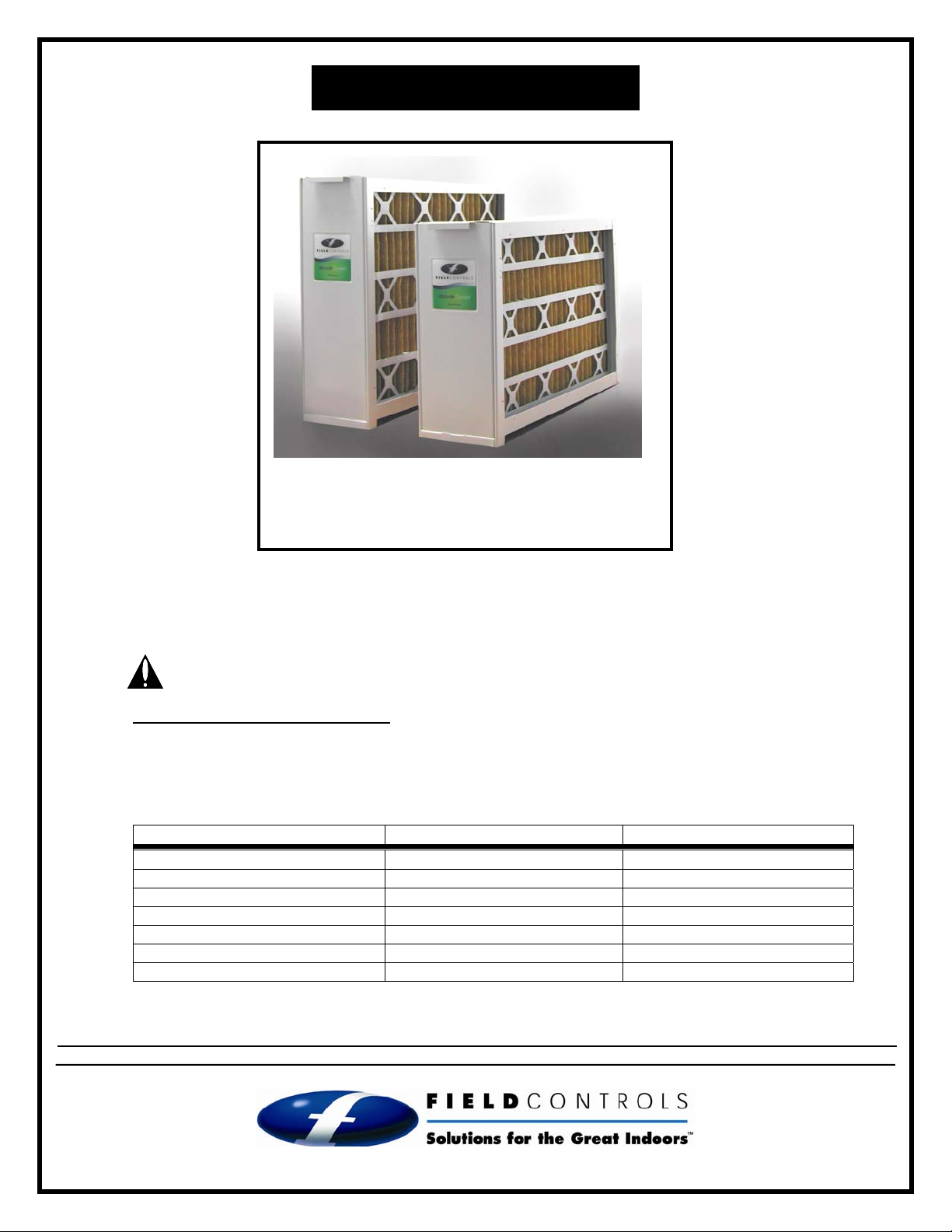
MEDIA AIR CLEANER
Models: FC-1400 & FC-2000
Items Included: 1) Cabinet
1) Media Filter
1) Installation Instruction Manual
NOTE: This device should be installed by a qualified agency* in accordance with the manufacturer’s installation instructions.
*The definition of a qualified agency is: any individual, firm, corporation or company which either in person or through a representative is
engaged in, and is responsible for, the installation and operation of HVAC appliances, who is experienced in such work, familiar with all
the precautions required, and has complied with all the requirements of the authority having jurisdiction.
WARNING: Read the installation instructions carefully and completely before proceeding with the installation.
GENERAL SYSTEM INFORMATION
Field Controls high efficiency series of media air cleaners are designed for installation into heating, ventilation,
air conditioning (HVAC) systems to reduce the amount of airborne particulate (1.0 micron and larger) including
pollen, dust and dander promoting better indoor air quality. The media air cleaner should be installed in the
return air system duct, such that all of the circulated air passes through the filter. For maximum filtering
performance, the air circulation fan should operate continuously.
Model FC - 1400 FC - 2000
Nominal Filter size 16” x 25” x 5” 20” x 25” x 5”
Air flow range 600-1400 CFM 600-2000 CFM
MERV rating 11 11
Filter Replacement P/N 46568500 46568600
Cabinet dimensions 16-1/4” x 24-7/8” x 7-1/8” 20-1/4” x 24-7/8” x 7-1/8”
Cabinet opening dimensions 13-7/8” x 22-1/2” 17-7/8” x 22-1/2”
UL filter media listing Class 2 Class 2
NOTE: FOR OPTIMUM PERFORMANCE, REPLACE THE MEDIA FILTER EVERY 6 TO 12 MONTHS.
DO NOT DESTROY
THESE INSTRUCTIONS MUST REMAIN WITH EQUIPMENT
2630 AIRPORT ROAD · KINSTON, NC 28504
Phone: 252-522-3031· Fax: 252-522-0214
Page 1
www.fieldcontrols.com
Page 2
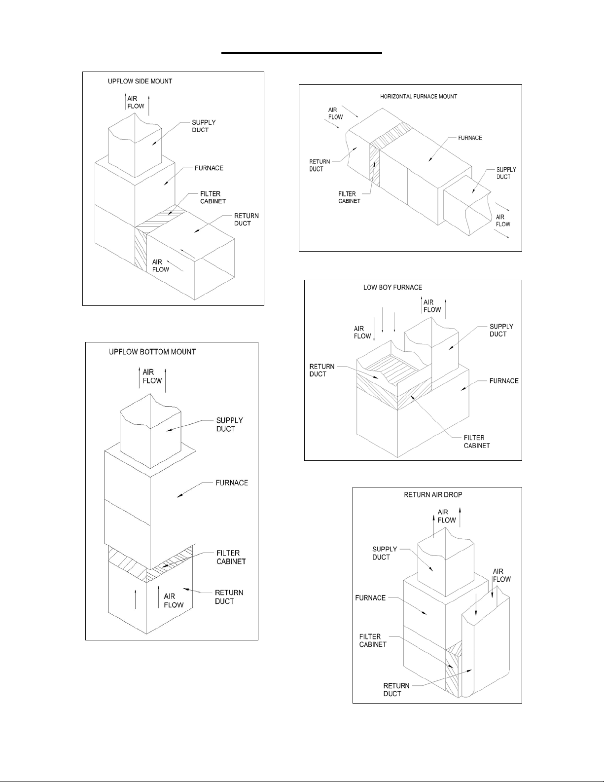
MOUNTING OPTIONS
Figure 1
Figure 3
Figure 2
Figure 4
Figure 5
Page 3

CAUTION:
Before installing a media filter into the HVAC system,
the Qualified Agency must consider the additional
pressure drop being added to the HVAC system.
1. The filter must be installed on the return side of
the HVAC system, between the return air duct
and the intake of the system blower. NEVER
install on the supply side of the HVAC system.
2. The filter access panel MUST be installed where
there is at least twenty-six (26) inches in front of it.
This allows clearance for the replacement of the
media filter.
3. Some installations may require a duct transition.
Transitions may be needed to reduce pressure
drop and maintain appliance efficiency. The
appliance must operate within the manufacturer’s
recommended temperature and pressure drop
requirements.
4. Check the flow capacity and pressure drop
(Figure 6) to determine the filter is properly sized.
Figure 6
INSTALLATION:
WARNING: Always shut off the electrical power supply before working on the appliance.
1. Refer to the typical mounting positions (Figures 1 to 5) for proper placement of the filter cabinet.
2. Remove the metal filter cabinet from the carton and plastic bag.
3. Remove the access panel door and pull the media filter (in plastic bag) out of the cabinet. DO NOT install the media
filter with the plastic bag around it.
4. Position cabinet so access panel is available for easy media filter replacement The access panel MUST be accessible
to remove and replace the media filter. (Note: Minimum of twenty-six (26) inches for front clearance).
5. Position the filter cabinet onto return air side of the appliance (Figures 1 to 5). Duct transitions may be required to
properly mount the filter cabinet.
6. When the filter cabinet is mounted directly to the appliance or existing duct, mark the inside opening of the filter cabinet
and all 12 mounting screw locations.
7. Drill the marked mounting holes with a 1/8 inch diameter drill bit. Remove the marked filter opening with metal cutting
shears or equivalent.
8. Attach filter cabinet to the appliance or duct work using #8 X 1/2 inch long sheet metal screws or pop rivets. Seal the
housing connections with aluminum duct tape or equivalent.
9. Remove media filter from the plastic bag and discard the plastic bag. TIP: Write the installation date on filter next to
directional arrow for future filter replacement reference. The media filter MUST be installed WITHOUT the plastic bag.
10. Install media filter into the filter cabinet.
11. Install the filter cabinet access panel.
12. Place appliance back into service. Appliance must operate within the appliance manufacturer’s recommended
temperature and pressure drop requirements.
Page 4

MAINTENANCE:
b
t
The media filter MUST be replaced periodically. The
reason is to maintain appliance operating efficiency
by minimizing pressure drop through the HVAC
system. The frequency of filter media replacement
depends on the operational environment. The need
for replacement is easily determined by a visual
inspection. Note: For optimum performance, replace
the media filter every 6 to 12 months.
EDIA FILTER REPLACEMENT PROCEDURE:
M
1. Turn off electrical power to the HVAC system.
2. Remove the filter cabinet access panel.
Note: “AIR FLOW” directional arrow, located on
existing media filter (Figure 6).
3. Remove the existing filter media.
4. Remove the new media filter from the plastic bag.
Tip: Re-use plastic bag to discard the used
media filter.
5. Check media filter directional arrow (→)! The
directional arrow MUST point in the direction of
air flow.
Tip: Write the installation date on media filter
next to directional arrow for future filter
replacement reference.
6. Install the new media filter.
7. Install the filter cabinet access panel.
8. Turn on electrical power to the HVAC system.
R
EPLACEMENT PARTS LIST:
Figure 7
Air cleaner Model Replacement filter size
FC - 1400 16 x 25 x 5
FC - 2000 20 x 25 x 5
Replacement filter
part number
46568500
46568600
Number of filters per carton
3
3
Limited Warranty
Field Controls, L.L.C. warrants that the following Field Controls, L.L.C. products sold hereunder, shall be free from defects in material and workmanship
under normal use for eighteen (18) months from date of manufacturing by the consumer excepting the provisions numbered below.
Provisions:
1. Field Controls shall have no obligation in the event the customer is unable to provide receipt showing the date the customer purchased the
product(s) or accurate date code information.
2. The product must be properly installed, maintained and operated under normal conditions.
3. Field Controls shall not be liable for any consequential and incidental damages, resulting from failure of a Field Controls, L.L.C. product, failure to
deliver, delay in delivery, delivery in nonconforming condition, or for any breech of contract or duty
customer.
4. Field Controls, L.L.C. products are often intended for use in specific applications. Field Controls, L.L.C. makes no warranty if a Field Controls,
L.L.C. product is used in applications other than intended.
5. Field Controls, L.L.C. makes no warranty of any kind in regard to any other manufacturer’s products distributed by Field Controls, L.L.C. Field
Controls, L.L.C. will pass on all warranties made by the manufacturer and where possible, will expedite the claim on behalf of the customer, bu
ultimately, responsibility for disposition of the warranty claim lies with the manufacturer.
etween Field Controls, L.L.C. and the
P/N 46567000 11/08
 Loading...