

Page 1
INSTALLATION AND USER MANUAL
R
T21WF
THERMOSTAT WITH AIRFLOW CONTROL
R
E
L
D
C
O
N
T
R
O
L
S
Wi
Fi
WiFi
Sleeping
Airflow %
Day
Tu
Living
AM
Schedule
R
Cool
Set To
COOL
Living
SYSTEM
AUTO
FANMENU MODE
F
I
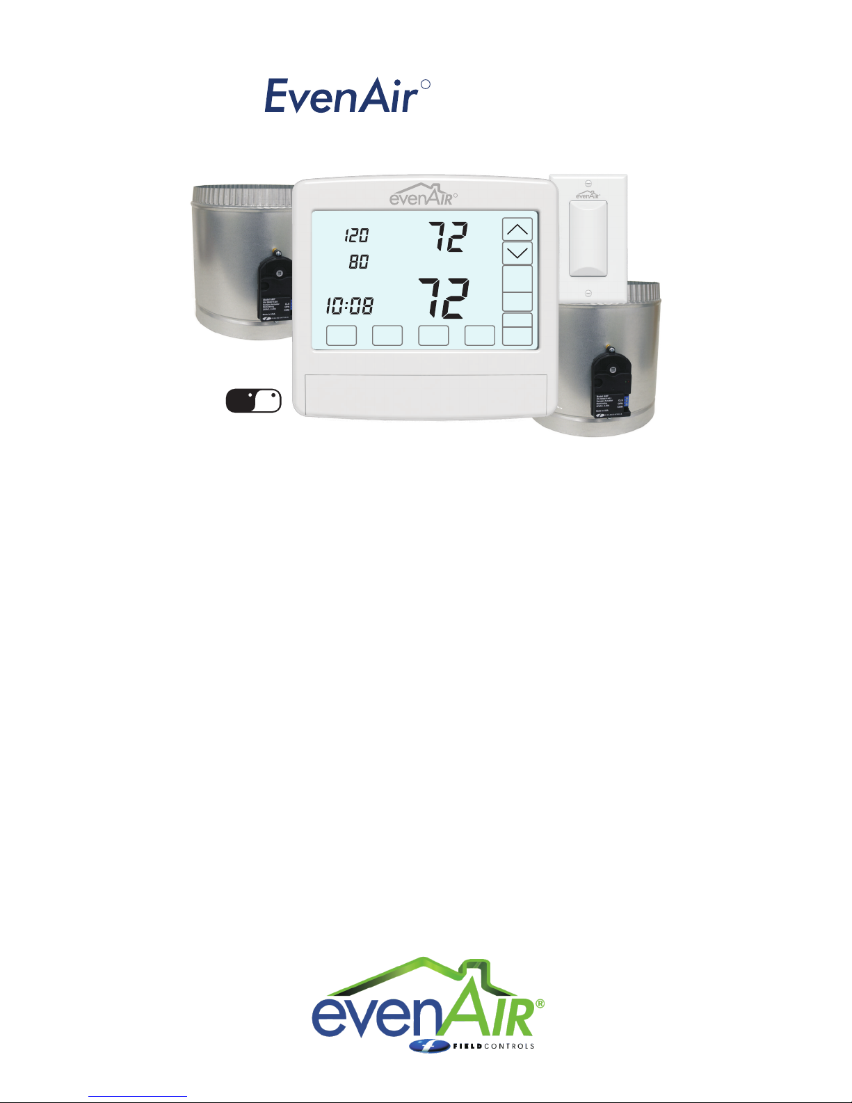
The EvenAir WiFi thermostat controls heating, cooling and AIRFLOW to the sleeping and living
areas in a home and provides remote access to your HVAC system using a smart phone, tablet or
PC. The thermostat is installed in the downstairs living area, a temperature sensor is installed in the
upstairs bedroom area and two modulating dampers are installed to control the airflow to the
living and sleeping area.
The EvenAir thermostat monitors the temperature at the sensor and the temperature at the
thermostat every 2 minutes during heating and cooling calls. If the temperatures are different, the
EvenAir thermostat automatically adjusts the modulating dampers 2% so that more airflow is
directed to the space that needs it for a uniformly comfortable home.
COMPONENTS:
EvenAir T21WF Thermostat
EvenAir TS51 or TS52 Wired Temperature Sensor(s) (sold separately)
EvenAir AMT Type Motorized Damper, With Terminals (sold separately)
READ THESE INSTRUCTIONS CAREFULLY AND COMPLETELY BEFORE PROCEEDING WITH THE INSTALLATION.
This device MUST be installed by a qualified agency in accordance with the manufacturer’s installation instructions.The definition of
a qualified agency is: any individual, firm, corporation or company which either in person or through a representative is engaged in,
and is responsible for, the installation and operation of HVAC applicances, who is experienced in such work, familiar with all the
precautions required, and has complied with all the requirements of the authority having jurisdiction.
Please retain these instructions after installation.
Installed By:_______________________________________ Phone: _____________________ Installation Date: _____________
P/N 780101703 3/18 Rev Awww.fieldcontrols.com
Page 2
Thank you for purchasing the EvenAir System from Field Controls. The EvenAir products are compatible
with any HVAC system having accessible 24VAC terminals.
FEATURES
SYSTEM MODES
Off, Heat, Cool, Auto
FAN MODES
Auto or Continuous
THERMOSTAT MODES
Hold, Schedule or Vacant
PROGRAMS PER DAY
Morning, Daytime, Evening and Night
PROGRAM FORMAT
Weekdays and weekend – 5/2
TEMPERATURE OVERRIDE
Temperature is held for 3 hours when adjusted in Schedule
mode.
AIRFLOW OVERRIDE
The airflow to the living area or sleeping area can be adjusted.
After 3 hours, the thermostat returns to automatic airflow
control.
AIRFLOW CONTROL
Airflow control can be turned off and the thermostat will operate
as a typical thermostat.
AIRFLOW LIMITS
Maximum airflow limits can be set for heating and cooling
modes during installation.
NIGHTTIME OPERATION
At night, the EvenAir thermostat uses the temperature sensor in
the sleeping area to control heating and cooling calls and
directs more airflow to the sleeping area.
COMPATIBLE EQUIPMENT
Gas/electric equipment with 2-stage heating and 1-stage
cooling or 1-stage heating and 2-stage cooling and heat
pumps with 2-stage heating and 2-stage cooling.
TEMPERATURE SENSOR
One TS51 sensor or two TS52 temperature sensors can be used
in the sleeping area.
MODULATING DAMPERS
Round or rectangular dampers using the AMT actuator and up
to 1 inch static pressure.
WiFI
Connects to the home WiFi network to provide remote access
via the internet using smart phone, tablet or PC.
POWER
Operates on 24VAC from the HVAC equipment using the R and
C wires.
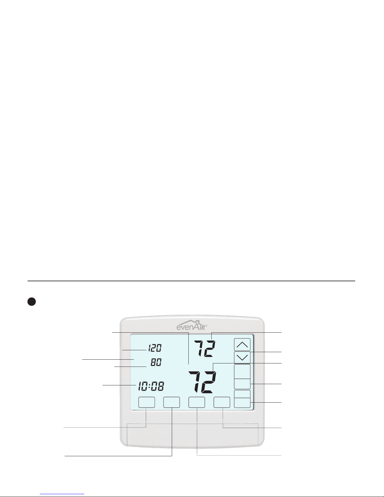
THERMOSTAT OVERVIEW
Press the touchscreen with your fingertip only, using a firm touch. Do not use a sharp object such as a pen or pencil.
!
The touchscreen is a resistive touch and responds differently than touchscreens found in smart phones/devices.
R
Displays the Thermostat Mode
HOLD, SCHEDULE or VACANT
Displays the sleeping area airflow
Displays WiFi status
Displays the living area airflow
Displays the time, day and
schedule. MORNING, DAYTIME,
EVENING or NIGHT
MENU Key
Displays User options.
MODE Key
Selects Thermostat Mode
HOLD, SCHEDULE or VACANT
WiFi
Sleeping
Airflow %
Living
Day
Tu
AM
Schedule
Cool
Set To
Living
COOL
SYSTEM
AUTO
FANMENU MODE
Displays the heating or
cooling temperature
UP/DOWN Keys
Displays the living area or
sleeping area temperature.
SYSTEM MODE Key
OFF, HEAT, COOL or AUTO
FAN MODE Key
AUTO or ON
ENTER Key
Used to save options and
return to thermostat operation
NEXT Key
Used to advance through
options
page 2 of 16 P/N 780101703 3/18 Rev A
Page 3
HOMEOWNER SECTION
HOMEOWNER
This manual is separated into two different sections: one for the Homeowner and one for the System Installer.
The Homeowner section contains information on features and operation of the thermostat along with
optional user settings available to the homeowner.
THERMOSTAT OPERATION AND USER SETTINGS
Features
EvenAir Thermostat Operation
1
Set Time and Day
2
Set System Mode
3
Set Fan Mode
4
Set Thermostat Mode
5
Changing Setpoint Temperature
Temperature Override
6
Displaying Upstairs Temperature
7
Overriding Automatic Airflow
8
9
Terminating Automatic Airflow
FEATURES
User Options
1
Set Schedule
2
Turn Automatic Airflow Control On/Off
3
Turn Nighttime Airflow Control On/Off
4
Set Nighttime Airflow in Heating
5
Set Nighttime Airflow in Cooling
Clean the Touchscreen
6
Turn Thermostat WiFi On
7
Start Linking WiFi Thermostat
8
Install Batteries
DISPLAYING THE LIVING AND BEDROOM AREA TEMPERATURE
The living area temperature is normally displayed. The bedroom area temperature can be displayed by touching
Living on the touchscreen. The temperature will change to the bedroom space temperature, indicated by Sleeping.
Touch Sleeping to return to displaying the Living area temperature.
NIGHTTIME AIRFLOW CONTROL
The Nighttime Airflow Control option is an energy saving feature where the thermostat uses the temperature sensor
in the bedroom area to control heating and cooling calls and directs more airflow to the bedroom at night
and less airflow to the unoccupied living . Nighttime Airflow Control begins at 10:00pm but can be changed
by accessing the schedule in the User Options. The airflow to the bedroom space defaults to 130% but can be
adjusted for both heating and cooling in the User Options. Nighttime Airflow Control is defaulted to On but can be
turned Off in the User Options. The homeowner should consider turning this option off if bedrooms are located on
the same floor as the living area and using the same airflow trunk as the living area.
AUTOMATIC OR MANUAL AIRFLOW CONTROL
Automatic Airflow Control is the thermostat default and is typically used by homeowners to maintain uniform
comfort throughout the home. However, homeowners with unusual work schedules, home offices, etc. may want to
use the manual airflow control feature. This features allows the homeowner to change the airflow level as desired
and hold that level indefinitely. This feature needs to be enabled using Installer Option 18. The homeowner then
needs to turn automatic airflow control off using the User Options. The Nighttime Airflow Control option is still
enabled but can be turned off, if desired, using the User Options.
AIRFLOW OVERRIDE
On occasion, homeowners may want to direct more airflow to an area. For example, during a party, more airflow
may be desired in the living area. The homeowner sets the airflow level to the area and the thermostat will hold
the airflow for 3 hours. After 3 hours, the thermostat returns to automatic airflow control.
area
area
AIRFLOW CONTROL TURNED OFF
In some installations, the EvenAir thermostat has been installed to control the system only. The thermostat operates
just like any other thermostat. The airflow control options are disabled and airflow is no longer displayed on the
thermostat.
WiFi REMOTE ACCESS
The EvenAir WiFi thermostat connects to the home’s WiFi network and provides remote access, via the internet, to your
home’s heating and cooling system from anywhere using a smart phone, tablet or PC.
page 3 of 16 P/N 780101703 3/18 Rev A
Page 4

HOMEOWNER SECTION
THERMOSTAT OPERATION
1
Set Time and Day
Touch here to change the time and day of the
week.
CHANGE THE HOUR
AM
NEXT
CHANGE THE MINUTE
AM
NEXT
CHANGE THE DAY OF THE WEEK
We
AM
i
Depending on the mode, setting the time
may reset the setpoint temperature to the
factory default heating or cooling setpoint.
Set System Mode
2
Touch the SYSTEM key to display the SYSTEM
MODES: OFF, HEAT, COOL or AUTO. In AUTO
or OFF, the setpoint for the last system call is
displayed.
Sleeping
Airflow %
Living
Day
Tu
MENU MODE
Sleeping
Airflow %
Living
Day
Tu
MENU MODE
Sleeping
Airflow %
Living
Day
Tu
MENU MODE
Sleeping
Airflow %
Living
Day
Tu
MENU MODE FAN
Schedule
AM
Schedule
AM
Schedule
AM
Schedule
AM
ENTER
ENTER
ENTER
Heat
Set To
Heat
Set To
Cool
Set To
Heat
Set To
Sleeping
Airflow %
Living
Day
Tu
AM
Touch the
UP/DOWN keys to
change the HOUR.
Touch NEXT.
Touch the
UP/DOWN keys to
change the MINUTE.
Touch NEXT.
Touch the
UP/DOWN keys to
change the DAY OF
THE WEEK.
Touch ENTER.
OFF
Heating and cooling
systems are off.
OFF
Living
SYSTEM
AUTO
FAN
HEAT
Only heating calls are
Living
setpoint is displayed.
SYSTEM
“HEAT” will blink in
AUTO
an active heating call.
FAN
enabled and heating
HEAT
COOL
Only cooling calls are
Living
enabled and cooling
COOL
setpoint is displayed.
SYSTEM
“COOL” will blink in
AUTO
an active cooling call.
FAN
AUTO
Heating or Cooling
Living
calls are enabled.
“HEAT” will blink in
AUTO
SYSTEM
an active heating call
AUTO
or “COOL” will blink
in an active cooling
call.
Schedule
Cool
Set To
Living
COOL
SYSTEM
AUTO
FANMENU MODE
3
Set Fan Mode
Touch the key to change the FAN MODES -
FAN
AUTO or ON.
Sleeping
Airflow %
Living
Day
Tu
AM
MENU MODE
Sleeping
Airflow %
Living
Day
Tu
AM
MENU MODE
4
Set Thermostat Mode
Touch the key to display the THERMOSTAT
MODE
Schedule
Schedule
Cool
Set To
Living
Cool
Set To
Living
AUTO
Fan is activated only
during heating or
COOL
cooling calls. This is
SYSTEM
the most commonly
AUTO
used setting.
FAN
ON
Fan is continuously
on.
COOL
SYSTEM
ON
FAN
MODES: HOLD, VACANT and SCHEDULE.
Sleeping
Airflow %
Living
Day
Tu
AM
MODE
Sleeping
Airflow %
Living
Day
Tu
AM
MODE
Sleeping
Airflow %
Living
Day
Tu
AM
MODE
Changing the Setpoint Temperature
5
Cool
Set To
Hold
Cool
Set To
Vacant
Cool
Set To
Schedule
HOLD MODE
Setpoint temperatures
are set by the user.
Living
COOL
No schedule is used.
SYSTEM
AUTO
FANMENU
VACANT MODE
Setpoint temperatures
are kept at the vacant
Living
COOL
temperatures set by
SYSTEM
the installer.
AUTO
FANMENU
SCHEDULE MODE
Setpoint temperatures
are changed at
Living
COOL
scheduled times
SYSTEM
defined by the user.
AUTO
FANMENU
The UP/DOWN keys are used to change the
setpoint temperature.
Sleeping
Airflow %
Living
Day
Tu
AM
MENU MODE
Schedule
Cool
Set To
Living
Touch the UP key to
raise setpoint
temperature.
COOL
SYSTEM
Touch the DOWN
AUTO
key to lower setpoint
FAN
temperature.
An active heating call is indicated by HEAT
blinking. An active cooling call is indicated by
COOL blinking.
Sleeping
Airflow %
Living
Day
Tu
AM
MENU MODE
Schedule
Heat
Set To
Living
Touch here to display
and change the
opposing setpoint
COOL
temperature.
SYSTEM
AUTO
FAN
Touch the UP/DOWN keys to change the setpoint
temperature for the opposing system. The
thermostat will return to displaying the active
setpoint after about 30 seconds.
page 4 of 16 P/N 780101703 3/18 Rev A
6
Temperature Override
To override the setpoint temperature:
Tu
Sleeping
Airflow %
Living
Day
Cool
Set To
Schedule
Living
AM
Touch the UP/DOWN
keys to adjust the
setpoint temperature.
COOL
After 3 hours, the
SYSTEM
AUTO
thermostat returns to
FANMENU MODE
normal thermostat
operation.
7
Displaying the Upstairs Temperature
The thermostat displays the temperature in the
downstairs living area and is indicated by Living.
The temperature in the upstairs sleeping area is
indicated by Sleeping. When the thermostat enters
Night Mode, the upstairs sleeping area temperature
will be displayed, indicated by Sleeping.
MENU
MENU
Sleeping
Airflow %
Living
Day
We
Sleeping
Airflow %
Living
Day
We
Cool
Set To
Schedule
AM
Cool
Set To
Schedule
Sleeping
AM
Press Living to display
the upstairs Sleeping
area temperature.
COOL
Living
SYSTEM
AUTO
FANMODE
The upstairs Sleeping
area temperature is
now displayed.
COOL
SYSTEM
Press Sleeping to
AUTO
FANMODE
display the Living
area temperature.
8
Overriding Automatic Airflow
Sleeping
Airflow %
Living
We
Sleeping
Airflow %
We
Cool
Set To
Hold
Eve
PM
MODE
Living
Eve
PM
Living
Hold
Touch the Airflow %
area to override
AUTOMATIC AIRFLOW
COOL
to the living area or
SYSTEM
the upstairs sleeping
AUTO
FANMENU
area.
Touch the UP key to
increase the airflow to
Living
the sleeping area or
COOL
touch the DOWN key
SYSTEM
to increase airflow to
AUTO
FANMENU MODE
the living area.
Airflow % will blink to indicate airflow override.
After 3 hours, the thermostat returns to automatic
operation. The override range is defined by the
installer during set up.
9
Terminating Airflow Override
Sleeping
Airflow %
Living
We
Sleeping
Airflow %
Living
We
Cool
Set To
Hold
Eve
PM
MODE
Eve
PM
MODE
Living
Hold
Living
To terminate Airflow
Override, touch the
AIRFLOW% area.
COOL
SYSTEM
AUTO
FANMENU
Then touch the
MODE key.
COOL
SYSTEM
AUTO
FANMENU
The thermostat returns to automatic airflow
control. The AIRFLOW % returns to the airflow
prior to the override.
Page 5

HOMEOWNER SECTION
USER OPTIONS
Factory Set Schedule
The thermostat comes pre-set with the
following energy-saving schedule for
weekdays (Mon-Fri) and weekends (Sat-Sun).
Using these settings can reduce your heating
/cooling expenses.
Monday - Friday
Morn
Day
Even
Nite
Saturday & Sunday
Morn
Day
Even
Nite
1
Change Factory Set Schedule
Sleeping
MENU
Tu
Airflow %
Living
Day
Schedule
AM
SELECTING THE WEEKDAY OR
WEEKEND SCHEDULE
WeTuMo ThFr
MENU NEXT ENTER
Schedule
SETTING THE MORNING
SCHEDULE START TIME.
Morn
WeTuMo
ThFr
MENU NEXT ENTER
Schedule
AM
SETTING THE MORNING
HEATING TEMPERATURE.
Morn
WeTuMo
ThFr
MENU NEXT ENTER
Schedule
AM
SETTING THE MORNING
COOLING TEMPERATURE.
Morn
WeTuMo
ThFr
MENU
Schedule
AM
NEXT ENTER
Continue setting the start times, heating setpoints,
cooling setpoints for the Day, Evening and Night
schedules.
Touch ENTER to save the schedule.
Time Heat Cool
6:00 AM
8:00 AM
6:00 PM
10:00 PM
Time Heat Cool
6:00 AM
8:00 AM
6:00 PM
10:00 PM
Touch the
Cool
Set To
Living
key to display
SCHEDULE. If no
COOL
key is touched, the
SYSTEM
thermostat returns to
AUTO
normal operation
FANMODE
after about 30
seconds.
Touch the UP key to
select the weekday
schedule
(MoTuWeThFr) or
touch the DOWN
key to select the
weekend schedule
(SaSu). Touch NEXT.
Touch the
UP/DOWN keys to
change the Morning
Start Time. Touch
NEXT.
Heat
Set To
Touch the
UP/DOWN keys to
change the Morning
Heating Setpoint.
Touch NEXT.
Touch the
Cool
Set To
UP/DOWN keys to
change Morning
Cooling Setpoint.
Touch NEXT.
70
62
70
62
70
62
70
62
MENU
75
83
75
78
75
83
75
78
2
Automatic Airflow Control On or Off
i
This option is only displayed if User Airflow
Control has been turned On by the installer in
the Installer Options.
i
Homeowners with an unusual schedule, home
office, etc. may want to use this option.
i
With Automatic Airflow Control Off, the
Nighttime Airflow option is still enabled. If
desired, the homeowner can turn the
Nighttime Airflow option off using User
Options.
Touch the MENU key until the following
thermostat screen is displayed.
Thermostat defaults
Airflow %
to Automatic Airflow
Control On and
automatically directs
more airflow to where
MENU
NEXT
ENTER
it’s needed.
To turn Automatic
Airflow %
Airflow Control OFF,
touch the DOWN
key. The user must
set the airflow when
NEXTMENU ENTER
Touch the key to save and go to next
MENU
airflow control is off.
option or touch the ENTER key to save the options
and return to normal thermostat operation.
3
Nighttime Airflow Control On or Off
i
This option is not displayed if Nighttime
Airflow Control has been turned off by the
installer using the Installer Options.
i
If bedrooms are located downstairs, consider
turning the Nighttime Airflow Control OFF.
NIGHTTIME AIRFLOW CONTROL defaults to On
and is used to save energy. The thermostat uses
the temperature sensor in the sleeping area for
controlling heating and cooling calls. The airflow
is increased to 130% to the sleeping area and the
airflow is reduced to 70% to the unused living
area. The thermostat displays the sleeping area
temperature.
Upstairs
Airflow %
Night
Touch the MENU key
to display
NIGHTTIME
AIRFLOW indicated
by nAF On or Off.
MENU NEXT ENTER
Upstairs
Airflow %
Night
Touch the UP key to
turn the option ON.
Touch the DOWN
key to turn the
option OFF.
MENU NEXT ENTER
Touch the MENU key to save and go to next
option or touch the ENTER key to save the options.
page 5 of 16 P/N 780101703 3/18 Rev A
3
Nighttime Airflow Control (cont.)
i
Default start time for Nighttime Airflow is
10:00pm but can be changed using User
Option 1 to change the Night Schedule Start
Time.
i
Default airflow level upstairs is 130%. If a
different airflow level is desired, use User
Option 4 to change the airflow level in heating
and User Option 5 to change the airflow level
in cooling.
4
Set the Nighttime Airflow in Heating
i
This option is not be displayed if Airflow
Control has been turned off.
This option is used to change the default
nighttime airflow in heating of 130% to a user
desired airflow level, not to exceed installer limits.
Sleeping
Airflow %
Night
MENU ENTER
Touch the key to display NIGHTTIME,
MENU
Heat
NEXT
UPSTAIRS AIRFLOW IN HEATING indicated by
nAF Heat.
Use the UP/DOWN keys to adjust the airflow.
Touch the MENU key to save and go to next
option or touch the ENTER key to save the option.
Set the Nighttime Airflow in Cooling
5
i
This option is not displayed if Airflow Control
has been turned off.
This option is used to change the default
nighttime airflow in cooling of 130% to a user
desired airflow level, not to exceed installer limits.
Sleeping
Airflow %
Night
MENU ENTER
Cool
NEXT
Touch the MENU key to display NIGHTTIME,
UPSTAIRS AIRFLOW IN COOLING indicated by
nAF Cool.
Use the UP/DOWN keys to adjust the airflow.
Touch the MENU key to save and go to next
option or touch the ENTER key to save the
options.
Page 6

HOMEOWNER SECTION
USER OPTIONS (continued)
6
Clean the Touch Screen
This option disables the touch screen for 30
seconds to enable the user to clean the touch
screen by wiping down with a soft, damp cloth.
Touch the MENU key
to display CLEAN
DISPLAY option
indicated by CL. To
NEXT ENTERMENU
7
Turn Thermostat WiFi On
This option turns WiFi access On or Off.
exit the option, touch
NEXT.
Touch ENTER to start
the 30 second count
OFF
down. The touch
screen is disabled
during this time.
Touch the MENU
key to display WiFi
On or Off option
indicated by NEt.
8
Start Linking WiFi Thermostat
This option starts the linking of the EvenAir
thermostat to the home’s WiFi network.
Touch the MENU
key to display WiFi
linking option On
or Off indicated by
Lnc.
ENTER
Touch the UP key to
select ON. Touch
the ENTER key to
start the linking
sequence.
ENTER
During the linking
sequence “WiFi” will
blink indicating the
thermostat is trying
to link to the home
network. Once the
Sleeping
Airflow %
WiFi
Living
Day
Tu
MENU MODE
Cool
Set To
Schedule
Living
COOL
AM
SYSTEM
AUTO
FAN
thermostat has
linked, “WiFi” will be on continuously indicating a
connection.
INSTALL / REPLACE AA BATTERIES
Two AA batteries power
the clock when 24VAC
power is lost. Slide the
battery cover downward
and install the two AA
batteries, paying
attention to the polarity.
- + - +
MENU ENTER
NEXT
Touch the UP key to
turn WiFi ON.
MENU ENTER
NEXT
User Options (Homeowner)
Factory Set Schedule
01
Monday through Friday
Morn
Day
Even
Nite
Saturday and Sunday
Morn
Day
Even
Nite
NA
Automatic Airflow Control (requires Installer Option 18
02
enabled or will not show up as a User Option
03
Nighttime Airflow Control
Set the Nighttime Airflow in Heating (will only show if
04
Nighttime Airflow Control is ON)
Set the Nighttime Airflow in Cooling (will only show if
05
Nighttime Airflow Control is ON)
06
Turning WiFi On/Off
07
Link Thermostat to Wireless network
08
Clean the Touch Screen (in seconds)
Schedule
Default Settings
Time Heat Cool
6:00 AM
8:00 AM
6:00 PM
10:00 PM
70
62
70
62
Time Heat Cool
6:00 AM
8:00 AM
6:00 PM
10:00 PM
70
62
70
62
Display Range Default
A Ac
n AF
nAF + Heat
nAF + Cool
nEt
Lnc
CL
On or Off
On or Off
%
%
On or Off
On or Off
N/A
130%
130%
75
83
75
78
75
83
75
78
On
On
Off
Off
30
Record User Selection if Changed
from Default Setting
Time Heat Cool
Time
Heat
Cool
Record User Selection if Changed
from Default Setting
N/A
N/A
page 6 of 16 P/N 780101703 3/18 Rev A
Page 7

INSTALLER SECTION
This manual is separated into two different sections: one for the Homeowner and one for the System Installer.
The Installer section contains setup and installation information of the thermostat with optional user
settings available to the homeowner.
INSTALLATION
i
!
CAUTIONS
Before installing the EvenAir comfort system, turn off
all power to your HVAC system.
Read and follow all instructions carefully.
Read entire manual before installing EvenAir products.
Follow all local electrical codes during installation. All
wiring must conform to local and national electrical
codes.
Use cautions when mounting components to surfaces
that may have concealed wiring beneath the surface.
When servicing EvenAir system or accessing products,
turn off all power to these items.
ATTENTION INSTALLER
1)
Install and wire components to the thermostat.
(see Wiring section)
2)
Place the thermostat on the subbase. Do not install
batteries.
3)
Turn power to the HVAC equipment On.
4)
Check for Error Messages. (see Error Message section)
5)
Set equipment options 1-5 if different than factory
default settings. (see Installer Options section).
6)
Test the installation using the Installer Test Menu.
(see Installer Test Menu section on page 13)
7)
Install batteries and set the time and day (see Installing
Batteries and Set Time and Day section)
REMOVE SUBBASE
Place a slotted screwdriver in the
slots as shown and rotate to
remove subbase from the
thermostat housing.
Airflow Control Off Option 17 turns off Airflow Control.
The thermostat controls the system, dampers fully open,
nighttime airflow control is disabled and airflow is no
longer displayed on the thermostat.
User Airflow Control can be enabled using Option 18.
User turns off automatic airflow control in the User
Options.
Nighttime Airflow Control is defaulted to ON. If
bedrooms are located downstairs, consider turning this
option Off using the User Options if bedrooms are not
on the same trunk.
ATTACH SUBBASE TO WALL
Attach the subbase to an interior wall and about 5-feet above
the floor as shown using the screws and wall anchors supplied.
The wires to the dampers,
HVAC equipment and the
temperature sensor pass
through the opening
between the terminals.
R
C
WOB
EQUIPMENT
Y
G
W2E/Y2
TS
T21
COM
CLS
OPN
Sleeping
COM
CLS
OPN
Living
TS
page 7 of 16 P/N 780101703 3/18 Rev A
Page 8

INSTALLER SECTION
INSTALL DAMPERS
Install a damper with an AMT actuator in the duct supplying air
to the sleeping area and wire the terminals to the
corresponding terminals on the T21. Install a second damper
with an AMT actuator in the duct supplying air to the living area
and wire it to the T21. Each damper uses 2.4VA of power.
Ensure that damper installation does not cause obstruction
!
to the damper blade.
When two or more dampers are required to define the sleeping
or living area, the damper may be wired in parallel. LEDs on
the damper actuator indicate when the damper is fully open
(green) or fully closed (red). When properly installed, the
dampers will never fully close.
Green LED
Red LED
WIRING
!
Warning!
Turn the power to the HVAC equipment off before wiring.
Gas/Electric, 2H/1C
Use 6-conductor, 18 or 20 gage, thermostat cable.
T21
Terminal
R
C
W/OB
Y1
G
W2E/Y2
Gas/Electric, 1H/2C
Use 6-conductor, 18 or 20 gage, thermostat cable.
T21
Terminal
R
C
W/OB
Y1
G
W2E/Y2
Wire Color
Red
Blue
White
Yellow
Green
Brown
Wire Color
Red
Blue
White
Yellow
Green
Brown
Equipment
Terminal
R, Rc, Rh
C
W, W1
Y, Y1
G
W2
Equipment
Terminal
R, Rc, Rh
C
W, W1
Y, Y1
G
Y2
Function
24VAC Power
Common
Stg1 Heating
Cooling
Fan
Stg2 Heating
Function
24VAC Power
Common
Stg1 Heating
Stg1 Cooling
Fan
Stg2 Cooling
DAMPER WIRING
!
Warning!
Turn the power to the HVAC equipment off before wiring.
Use 3-conductor, 18 or 20 gage, thermostat cable to wire from
the T21 Thermostat to the sleeping and living area dampers.
There are separate terminals for the sleeping and living area
dampers.
i
Ensure the damper for the sleeping area is wired to the
terminals labeled SLEEPING and the damper for the living
area is wired to the terminals labeled LIVING.
T21
Terminal
COM
CLS
OPN
Multiple dampers can be used to construct the sleeping or living
zones. Daisy chain terminals– COM to COM, OPN to OPN and
CLS to CLS.
Wire Color
White
Red
Green
Terminal
COM
CLS
OPN
FunctionDamper
Common
Closes Damper
Opens Damper
Heat Pump, 1 Compressor
Use 6-conductor, 18 or 20 gage, thermostat cable.
T21
Terminal
R
C
WOB
Y1
G
W2E/Y2
Wire Color
Red
Blue
White
Yellow
Green
Brown
Equipment
Terminal
R, Rc, Rh
C
O or B
Y, Y1
G
W, W2 or E
Function
24VAC Power
Common
Rev Valve
Compressor
Fan
Aux Heat
Heat Pump, 2-Compressor
Use 6-conductor, 18 or 20 gage, thermostat cable.
T21
Terminal
R
C
WOB
Y1
G
W2E/Y2
Wire Color
Red
Blue
White
Yellow
Green
Brown
Equipment
Terminal
R, Rc, Rh
C
O or B
Y, Y1
G
Y2
Function
24VAC Power
Common
Rev Valve
Stg1 Compressor
Fan
Stg2 Compressor
page 8 of 16 P/N 780101703 3/18 Rev A
Page 9

INSTALLER SECTION
TEMPERATURE SENSOR WIRING
!
Warning!
Turn the power to the HVAC equipment off before wiring.
Use 2-conductor, 18 or 20 gage, thermostat cable to wire from
the T21WF Thermostat to the temperature sensor in the sleeping
area.
i
Single Sensor Installation
Use one (1) Model TS51 sensor.
i
Dual Sensor Installation
Use two (2) Model TS52 sensors.
T21WF
Terminal
TS
TS
Wire Color
White
Red
HAND
TIGHTEN
Terminal
SNR
SNR
Printed circuit board
Brass washer
Place wire between brass washer
and the printed circuit board and
hand tighten screw.
FunctionSensor
Thermistor
Thermistor
WIRING DIAGRAM
Sleeping Area
Damper
GE HP
Y2
Y1
R
C
G
W2
G G
Y Y
W
C C
R R
Y2
E
O or B
HVAC System
Model T21WF
Thermostat (in living area)
W/OB
EQUIPMENT
W2E/Y2
TS
T21WF
Model AMT
PN 580011401
Damper Actuator
Modulating
24VAC,2.4VA
Made in USA
Living Area
Damper
Model AMT
PN 580011401
Damper Actuator
Modulating
24VAC,2.4VA
Made in USA
F I E L D
F I E L D
C NO O LT SR
C NO O LT SR
OPN
COM
OPN
COM
Reference Electrical Wiring DWG: 780301202
CLS
CLS
COM
CLS
SleepingLiving
OPN
COM
CLS
OPN
TS
The TS5 sensor can be installed
in a single gang box or directly
to the wall using the hardware
provided.
Model TS51 (one)
Temperature Sensor
for Sleeping Area
-OR-
Model TS52 (two)
Temperature Sensors
for Sleeping Area
(temperatures are
averaged)
page 9 of 16 P/N 780101703 3/18 Rev A
Page 10

INSTALLER SECTION
INSTALLER OPTIONS
These set up features should only be accessed by a qualified installer during initial EvenAir thermostat
installation set up. The homeowner would not normally access these product set up features.
Record Installed
Selection if Changed
Option
Description
01
Equipment Type
Reversing Valve
02
(Only displayed if HP selected in Option 1)
03
Compressor Stages
04 Heating Stages Htg 0, 1 or 2 1
Fan Operation.
05
(Only displayed if GE selected in Option 1)
06
Compressor Minimum Off Time (minutes).
07
Gas Minimum Off Time (minutes).
08
Minimum Run Time (minutes).
On-Off Temperature Differential
09
10
11
12
13
14
15
16
17
18
19
20
21
22
23
24
25
0 Cooling On 1 above setpoint, Off at setpoint. Heating On1 below setpoint, Off at setpoint.
1 Cooling On 1 above setpoint, Off .5 below setpoint. Heating On1 below setpoint, Off .5 above setpoint.
2 Cooling On 1 above setpoint, Off 1 below setpoint. Heating On1 below setpoint, Off 1 above setpoint.
Smart Recovery.
Vacant Heating Setpoint.
Vacant Cooling Setpoint.
Calibrate Living Area Sensor
Calibrate Sleeping Area Sensor.
Airflow Update Time
Night Level LCD Backlight
Airflow Control On or Off
Enable User Airflow Control
Up Stage Time
Maximum Airflow in Heating to the
Sleeping Area.
Maximum Airflow in Cooling to the
Sleeping Area.
Maximum Airflow in Heating to the
Living Area.
Maximum Airflow in Cooling to the
Living Area.
Maximum Temperature Difference
Between Sleeping and Living area.
Factory Restore
o o
o o o o
o o o o
Display
rEV
Cpr
Fan
Cot
HOt
r n t
O O
S r
+ Heat
V A C
V A C
+ Cool
C A L
C A L
A F t
BL
+ Night
AFC
UAC
USt
HAF+Heat
CAF+Cool
HAF+Heat
CAF+Cool
diF
Fr
GE or HP
0 or 1 (GE),
0 to 2 (HP)
GA(Down)
or EL(Up)
o
0n(Up) or
Off(Down)
1 to 20 minutes 2
On(Up) or
Off(Down)
On(Up) or
Off(Down)
On(Up) or
Off(Down)
5 to 30 minutes
100 to 160%
100 to 160%
100 to 160%
100 to 160%
No(Next or Enter) or
Yes(UP Key then ENTER)
Range
Gas/Electric
o or b
0 to 9
0 to 9
0 to 9
0, 1 or 2
44 to 75
74 to 95
+/- 5
+/- 5
0 to 10F
Default
O
1 (GE),
2 (HP)
GA
2
0
2
1
Off
65
80
0
0
On
On
Off
10
150%
140%
150%
140%
2F
No
from Default Setting
N/A
INSTALLATION NOTES:
page 10 of 16 P/N 780101703 3/18 Rev A
Page 11

INSTALLER SECTION
ACCESSING INSTALLER OPTIONS
To access the Installer Options, and
the hidden Enter key for 7 seconds until
HOLD
the first Option appears on the screen.
Sleeping
Airflow %
Living
Day
Tu
AM
MODE
The hidden BACK
key can be used to
return to previous
TOUCH HOLD and this key
for 7 seconds to access the
Installer Options.
options.
Press the touchscreen with your fingertip
!
only, using a firm touch. Do not use a sharp
object such as a pen or pencil.
The NEXT key is used to display the next
!
option.
The ENTER key is used to save options and
!
return to normal thermostat operation.
The hidden BACK key is used to return to
!
previous options and is located to the left of
the NEXT key.
01 Selecting the Equipment Type
Factory Default: GE. Range: GE or HP
This option is used
to select gas/electric
or heat pump
equipment.
Use the UP/DOWN
keys to select
gas/electric (GE) or heat pump (HP).
Touch NEXT or ENTER.
02 Reversing Valve
(Only displayed if Heat Pump equipment,
HP is selected in Option 01)
Factory Default: O. Range: o or b
This option is used
to select an O or B
type reversing valve.
Use the UP/DOWN
keys to select o for
O-Type or b for B-Type.
Touch NEXT or ENTER.
Schedule
TOUCH
Cool
Set To
Living
Option
NEXT
Option
NEXT ENTER
COOL
SYSTEM
AUTO
FANMENU
ENTER
03 Setting the Compressor Stages
Factory Default: 1 . Range: 0 or 1
This option is used to set the number of
compressor stages.
Use the UP/DOWN
keys to set 0 or 1
Option
stage.
Touch NEXT or
ENTER.
NEXT ENTER
04 Setting the Heating Stages
Factory Default: 1 Stage. Range: 0, 1 or 2
Use the UP/DOWN
keys to set 0, 1 or 2
Option
stage.
Touch NEXT or
ENTER.
NEXT ENTER
05 Setting the Fan Operation
(Only displayed if Gas/Electric equipment,
GE, is selected in Option 01)
Factory Default: Gas. Range: GA or EL
Use the UP key to
select “EL” for electric
Option
operation where the
thermostat activates
the indoor fan (G
terminal) during
NEXT ENTER
heating calls or DOWN key to select GA for gas
operation where the equipment plenum sensor
activates the indoor fan in heating calls.
Touch NEXT or ENTER.
06 Compressor Minimum Off Time
Factory Default: 2 Min. Range: 0 to 9 Min.
Use the UP/DOWN
keys to change the
Option
minimum off time
(minutes) before
restarting the
compressor.
NEXT ENTER
Touch NEXT or ENTER.
07 Heating Minimum Off Time
Factory Default: 0 Min. Range: 0 to 9 Min.
Use the UP/DOWN
keys to change the
minimum off time
(minutes) before
restarting a gas
furnace or electric
strip heater.
Option
NEXT ENTER
08 Minimum Run Time
Factory Default: 2 Min. Range: 0 to 9 Min.
Use the UP/DOWN
keys to change the
Option
minimum run time
(minutes) before
turning a system off.
NEXT ENTER
Touch NEXT or ENTER.
09 Setting On-Off Temp Differential
Factory Default: #1. Range: 0, 1 or 2.
Use the UP/DOWN
keys to select 0, 1,
Option
2.
Touch NEXT or
ENTER.
Differential Mode0
Differential Mode1
Differential Mode2
o
1.0 On/Off Span.
o
1.5 On/Off Span.
o
2.0 On/Off Span.
NEXT ENTER
10 Smart Recovery
Factory Default: Off. Range: On or Off.
Smart recovery initiates a heating or cooling call
so that the space is at temperature when the
setback period ends.
Use the UP key to
select ON to turn on
Option
smart recovery or
the DOWN key to
select OF to turn
smart recovery off.
NEXT ENTER
Touch NEXT or ENTER.
11 Vacant Heating Setpoint
Factory Default: 65 F.
o
Range: 44 F to 75 F
Use the UP/DOWN
keys to select the
heating temperature
o o
Option
Heat
Vacant
when the space is
vacant.
NEXT ENTER
Touch NEXT or ENTER.
12 Vacant Cooling Setpoint
Factory Default: 80 F.
Use the
UP/DOWN
o
keys to select the
cooling temperature
when the space is
vacant.
Touch NEXT or ENTER.
Range: 74 F to 95 F
o o
Option
NEXT ENTER
Cool
Vacant
Touch NEXT or ENTER.
page 11 of 16 P/N 780101703 3/18 Rev A
Page 12

INSTALLER SECTION
13 Calibrate Living Area Temperature Sensor
Factory Default: None.
Use the UP/DOWN
keys to change the
Living area
temperature to the
temperature that the
user feels is correct.
Touch NEXT or ENTER.
Range - +/-5
o
Option
Living
NEXT ENTER
14 Calibrate Sleeping Area Temperature Sensor
Factory Default: None.
Use the UP/DOWN
keys to change the
Sleeping area
temperature to the
temperature that the
user feels is correct.
Touch NEXT or ENTER.
Range - +/-5
o
Option
Sleeping
NEXT ENTER
15 Airflow Update Time
Factory Default: 2 Min. Range: 1 to 20 Min.
This is the frequency, in minutes, that the damper
position is updated.
UP/DOWN
Use the
keys to set the time
Option
in minutes to update
the sleeping and
living area airflow.
NEXT ENTER
Touch NEXT or ENTER.
16 Night Level LCD Backlight
Factory Default: On. Range: On or Off.
The LCD has a low
level backlight that
can be used as a
Option
Night
night light.
Use the key to
UP
NEXT ENTER
turn the low level
backlight ON or touch the key to turn
DOWN
OFF.
Touch NEXT or ENTER.
17 Airflow Control, On or Off
Factory Default: On. Range: On or Off.
This option turns the automatic airflow control on
or off. If off, the dampers fully open, nighttime
airflow options are disabled and airflow is no
longer displayed on the thermostat.
UP
Use the key to
select ON for airflow
control or touch the
key to select
DOWN
OFF to disable
airflow control.
Touch NEXT or ENTER.
If Airflow Control was off and is now being turned on,
the Nighttime Airflow option can be turned on using the
User Options.
Sleeping
Airflow %
Living
Option
NEXT ENTER
18 Enable USER Airflow Control
Factory Default: Off. Range: On or Off.
Homeowners with an unusual work schedule,
home office, etc. may want to use this option.
When turned On, this option enables the user to
turn off automatic airflow control in the User
Options. Airflow is adjusted by the homeowner.
23 Maximum Airflow in Cooling to the Living Area
Factory Default: 140%. Range: 100% to 160%.
Use the
UP/DOWN
keys to select the
maximum allowable
airflow in cooling to
the living area.
Nighttime Airflow option is still enabled but can
be turned off using the User Options.
Use the key to
UP
select ON to enable
Option
the user to turn off
automatic airflow
control in the user
options.
Touch NEXT or ENTER.
NEXT ENTER
Touch NEXT or ENTER.
24 Maximum Temperature Differential
Factory Default: 2 F.
This is the maximum allowable temperature
difference between the sleeping and living area
temperatures. When the temperature difference is
equal to or greater than the allowed differential,
o
Range: 0 to 10 F
the airflow is adjusted.
19 Upstaging Time
Factory Default: 10 min. Range: 5 to 30 min.
UP/DOWN
Use the
keys to set the time at
which second stage
heating or cooling is
activated.
Touch NEXT or ENTER.
Option
NEXT ENTER
Use the
UP/DOWN
keys to select the
maximum allowable
temperature
difference between
the sleeping and
living area.
Touch NEXT or ENTER.
25 Factory Restore
For options 20 - 23, use the installer test
o
n the following page to determine the
imum allowable airflow.
max
20 Maximum Airflow in Heating to Sleeping Area
Factory Default: 150%. Range: 100% to 160%.
UP/DOWN
Use the
keys to select the
maximum allowable
airflow in heating to
the sleeping area.
Touch NEXT or ENTER.
Sleeping
Airflow %
Option
Heat
NEXT ENTER
WARNING! Factory Restore resets ALL settings.
To exit this option,
touch or NEXT
ENTER, or the hidden
Back key.
To restore factory
settings, touch the
key to display
UP
YES then touch
ENTER.
21 Maximum Airflow in Cooling to the Sleeping Area
Factory Default: 140%. Range: 100% to 160%.
UP/DOWN
Use the
keys to select the
Sleeping
Airflow %
Option
Cool
maximum allowable
airflow in cooling to
the sleeping area.
NEXT ENTER
Touch NEXT or ENTER.
22 Maximum Airflow in Heating to the Living Area
Factory Default: 150%. Range: 100% to 160%.
UP/DOWN
Use the
keys to select the
maximum allowable
airflow in heating to
the living area.
Touch NEXT or ENTER.
page 12 of 16 P/N 780101703 3/18 Rev A
Airflow %
Living
Option
Heat
NEXT ENTER
Airflow %
Living
Option
o o
Option
Option
Option
Cool
NEXT ENTER
NEXT
ENTER
NEXT ENTER
NEXT
ENTER
Page 13

INSTALLER SECTION
ACCESSING THE TEST MENU
The Test Menu is used to test the Indoor Fan
Operation, Allowable Heating Airflow Limits and
Allowable Cooling Airflow Limits.
The Test Menu can also be used to perform the
HERS Total Airflow test. TEST 05-06 activates a
cooling call and opens both dampers to 100%
enabling the installer to perform the test.
To access the Test Menu, and the
hidden Next key for 7 seconds until the fan test
screen (TEST 01) appears.
Sleeping
Airflow %
Living
Day
Tu
AM
TOUCH HOLD and this key for 7 seconds
to access the Installer Options.
01-02 Testing Indoor Fan Operation
This test is used to verify that the indoor fan is
operating correctly.
In TEST 1, the Fan is
Off.
NEXT
Touch to go to
TEST 2 to turn on the
indoor fan. Verify the
fan is operating and
delivering airflow to
the sleeping and
living area.
NEXT
Touch to go to
Testing Heating
Airflow Limits.
TOUCH HOLD
Cool
Set To
Schedule
Sleeping
Airflow %
Living
Sleeping
Airflow %
Living
Living
Test
NEXT
Test
NEXT
COOL
SYSTEM
AUTO
FANMENU MODE
FANENTER
FANENTER
03-04 Testing Heating Airflow Limits
This test is used to determine the maximum
allowable airflow to the sleeping area and the
living area in HEATING.
In TEST 3, the system
is Off.
NEXT
Touch to go to
TEST 4 to activate
heating. Verify the
equipment is
operating.
To determine the
maximum allowable
airflow to the
Sleeping Area, touch
UP
the key until the airflow is too great and
causes noise or annoyance. Lower the airflow
using the key until it is acceptable. This is
DOWN
the maximum allowable airflow in heating to the
sleeping area. Record the airflow value.
Maximum Allowable Airflow in Heating
To determine the
maximum allowable
airflow to the living
area, touch the
DOWN
key until the
airflow is too great
and causes noise or annoyance. Increase the
airflow using the key until it is acceptable. This
is the maximum allowable airflow in heating to
the living area. Record the airflow value.
Maximum Allowable Airflow in Heating
Touch to go to Testing Cooling Airflow
NEXT
Limits.
Sleeping
Test
Airflow %
Living
Sleeping
Test
Airflow %
Living
to the Sleeping Area
Sleeping
Test
Airflow %
Living
UP
to the Living Area
Heat
NEXT
ENTER
Heat
NEXT
ENTER
Heat
NEXT ENTER
05-06 Testing Cooling Airflow Limits
This test is used to determine the maximum
allowable airflow to the Sleeping and Living
Areas in COOLING.
The test can also be used to perform the HERS
Total Airflow test. The test activates a cooling call
and opens both dampers to 100%.
In TEST 5, the system
is Off.
NEXT
Touch to go to
TEST 6 to activate
cooling. Verify the
equipment is
operating.
To determine the
maximum allowable
airflow to the
sleeping area, touch
UP
the key until the airflow is too great and
causes noise or annoyance. Lower the airflow
using the key until it is acceptable. This is
DOWN
the maximum allowable airflow in cooling to the
sleeping area. Record the airflow value.
Maximum Allowable Airflow in Cooling
To determine the
maximum allowable
airflow to the Living
Area, touch the
key until the
DOWN
airflow is too great
and causes noise or annoyance. Increase the
airflow using the key until it is acceptable. This
is the maximum allowable airflow in cooling to
the living area. Record the airflow value.
Maximum Allowable Airflow in cooling
Touch to end testing and return to normal
ENTER
thermostat operation.
Sleeping
Test
Airflow %
Living
Sleeping
Test
Airflow %
Living
to the Sleeping Area
Sleeping
Test
Airflow %
Living
UP
to the Living Area
Cool
NEXT ENTER
Cool
NEXT
ENTER
Cool
NEXT ENTER
Enter the maximum airflow limits using Options
20 through 23 of the installer menu.
page 13 of 16 P/N 780101703 3/18 Rev A
Page 14

INSTALLER SECTION
Error Messages:
!
Blank LCD
When the equipment is
powered up, a blank LCD
indicates that there is no power
to the thermostat. Check the
wiring from the thermostat to
the equipment for errors.
No Power Message
nP is displayed when there is
no power to the system. If the
message is displayed when
the system is powered, check
the wiring from the thermostat
to the system for errors.
Sleeping
Airflow %
Tu
Day
Living
Cool
Set To
Schedule
Living
AM
Sensor Error Message
nS is displayed when there
is an error with the
temperature sensor(s).
Check for open wires or
shortages.
When the nS message is displayed, the thermostat will
continue to control the system and automatically opens
both dampers and disables airflow control until the
sensor error is corrected.
Airflow %
Tu
Sleeping
Living
Day
Cool
Set To
Schedule
Living
AM
COOL
SYSTEM
AUTO
FANMENU MODE
COOL
SYSTEM
AUTO
FANMENU MODE
Install batteries only after successfully testing
!
the installation using the Installer Test Menu.
INSTALL BATTERIES
The batteries power the clock
when 24VAC power is lost. Slide
the battery cover downward and
install the two AA batteries as
shown.
Press the touchscreen with your fingertip only,
!
using a firm touch. Do not use a sharp object
such as a pen or pencil. The touchscreen is a
resistive touch and responds differently than
touchscreens found in smart phones/devices.
Set Time and Day
Touch here to change the time
and day of the week.
Sleeping
Airflow %
Tu
Day
Living
Cool
Set To
Schedule
AM
Living
COOL
SYSTEM
AUTO
FANMENU MODE
CHANGE THE HOUR
Touch the UP/DOWN keys to
change the HOUR. Touch NEXT.
AM
ENTER
NEXT
CHANGE THE MINUTE
Touch the UP/DOWN keys to
change the MINUTE. Touch NEXT.
AM
ENTER
NEXT
CHANGE THE DAY OF THE WEEK
Touch the UP/DOWN keys to
change the DAY OF THE WEEK.
We
AM
ENTER
Touch ENTER to save and return to
normal thermostat operation.
page 14 of 16 P/N 780101703 3/18 Rev A
Page 15

MAINTENANCE AND TROUBLESHOOTING
DAMPER OPERATION
Problem - No airflow to the sleeping area AND living
area registers
Turn system off immediately. Both dampers may be wired
backwards at the subbase or at the damper actuator (closing
rather than opening).
Problem - No airflow to the sleeping area OR living
area registers
Turn system off. One of the dampers may be wired backwards
at the subbase or at the damper actuator (closing rather
than opening).
Problem - When directing airflow to the sleeping area, the
airflow is actually directed to the living area, and when
directing the airflow to the living area, the airflow is actually
directed to the sleeping area.
Turn system off. Check if the dampers are switched (sleeping
area damper is wired to the living area terminals and the
living area damper is wired to the sleeping area terminals.)
COMFORT CONCERNS
Problem - Downstairs bedroom is too cold or too hot at night.
The Nighttime Airflow Control option directs more airflow to the
sleeping area and less airflow to the unoccupied living area. If
the downstairs bedroom is on the same HVAC trunk as the
living area, the downstairs bedroom may become uncomfortable
at night. Turn off the Nighttime Airflow Control option using the
User Options.
SENSOR INSTALLATION
Problem - nS message on thermostat.
Check that the sensor is wired correctly. Check for a short in
the sensor wiring.
Problem - Sleeping area temperature reading very high or
very low.
Check that the correct sensor(s) have been used. One TS51
sensor is used in a single sensor installation. Two TS52
sensors are used in a dual sensor installation.
Problem - The room temperature on the thermostat seems
too high or too low.
The thermostat is factory calibrated within 1 degree.
However, if a homeowner finds the temperature “feels”
too high or too low, the thermostat can be calibrated to
what the homeowner feels is the correct temperature using
Installer option 13 for the living area and option 14 for
the sleeping area.
SPARE PARTS AND ACCESSORY LIST
Field Controls
Part Number
580011101
580011102
580011301
580011302
580011401
580011405
580011406
Model
Number
T21
T21WF
TS51
TS52
AMT
IS
DS
MD-#
MD-LxH
Description
Programmable wired thermostat w/ airflow control for GE equipment with 1H/1C, 2H/1C or 1H/2C,
or HP equipment with 2H/2C
Programmable wired thermostat w/ airflow control for GE equipment with 1H/1C, 2H/1C or 1H/2C,
or HP equipment with 2H/2C. WiFi Enabled
Wired temperature sensor for the sleep area. Single sensor installation.
Wired temperature sensor for the sleep area. Dual sensor installation.
Replacement modulating actuator control, 3 wire.
Replacement idler shaft for AMT and AMJ actuators.
Replacement drive shaft for AMT and AMJ actuators.
EvenAir Round Balance Damper, 3 Wire. Sizes - 4” - 20” diameter.
EvenAir Rectangular Balance Damper, 3 Wire. Sizes - 8”, 10” and 12” Heights, up to 24” Length.
page 15 of 16 P/N 780101703 3/18 Rev A
Page 16

This manual may be downloaded and printed from the Field Controls website (www.fieldcontrols.com)
WARRANTY
For warranty information about this or any Field Controls product, visit:
www.fieldcontrols.com
Field Controls Technical Support
1.800.742.8368
fieldtec@fieldcontrols.com
Field Controls Customer Service
1.252.522.3031
sales@fieldcontrols.com
9154 Stellar Ct
Phone: 252.522.3031 Fax: 252.522.0214
Corona, CA 92883
c
Field Controls, LLC
www.fieldcontrols.com
2630 Airport Road
Kinston, NC 28504
P/N 780101703 3/18 Rev A
 Loading...