

Page 1
INSTALLATION MANUAL
R
H32
WIRING HUB
R
F I E L D
C NO O LT SR
Model H32
PN 580011201
Wiring Hub
24VAC, 10VA
Made in USA
The EvenAir H32 wiring hub is installed at the equipment. It is connected to the T32 or T32WF
thermostat using the existing or new 4-wire thermostat cable that normally connects the thermostat
to the equipment. The equipment is wired directly to the Wiring Hub, The upstairs sensor can be
either a wired or wireless sensor. Wireless sensors require the ER1 radio module that plugs into the
wiring hub. An outdoor temperature sensor can also be used to control fossil fuel heating in a dual
fuel heat pump or to control a whole house fan or economizer.
The EvenAir wiring hub can be used to control humidification and de-humidification, fresh air
intake per ASHRAE 62.2, ERVs or HRVs, whole house fans and economizers.
COMPONENTS:
READ THESE INSTRUCTIONS CAREFULLY AND COMPLETELY BEFORE PROCEEDING WITH THE INSTALLATION.
This device MUST be installed by a qualified agency in accordance with the manufacturer’s installation instructions.The definition of
a qualified agency is: any individual, firm, corporation or company which either in person or through a representative is engaged in,
and is responsible for, the installation and operation of HVAC appliances, who is experienced in such work, familiar with all the
precautions required, and has complied with all the requirements of the authority having jurisdiction.
Installed By:_______________________________________ Phone: _____________________ Installation Date: _____________
H32 Wiring Hub For Wireless Temperature Sensors
T32 or T32WF Thermostat
AMJ type Modulating Dampers
1 or 2 TSER Wireless Sensors
1 ER1 Plugin Radio Module
1 TS51 or 2 TS52 Wired Temp Sensors
Please retain these instructions after installation.
P/N 780101720 3/18 Rev Awww.fieldcontrols.com
Page 2
Thank you for purchasing the EvenAir System from Field Controls. The EvenAir products are compatible
with any HVAC system having accessible 24VAC terminals.
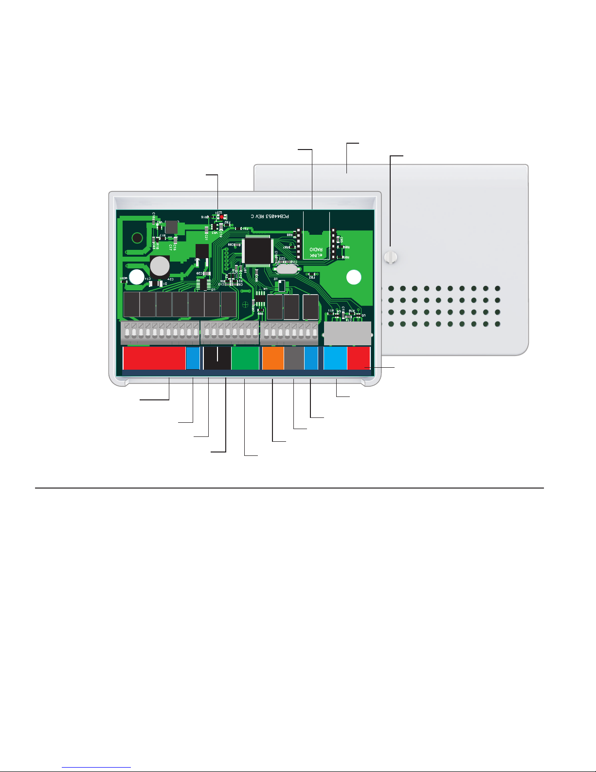
WIRING HUB OVERVIEW
Optional eLink Radio Module plugs into connectors.
24VAC Power Indicator.
Relay
Relay
Relay
Relay
HVAC
G
W2/E
Y2DSHFR
RCW/BOY
Terminals for wiring
to HVAC equipment.
Terminals for humidifier
Terminals for outdoor temperature sensor
Terminals for upstairs
wired temperature sensor
Relay
ODT
HFR
SENSORS
Relay
ODT
SLP
Relay
SLP
Cover.
Relay
Relay
Relay
ERV/HRV
GND
+5VSASB
TSTAT
24V
OPN
COM
WH FAN
DAMPR DAMPR
OPN
COM
FR AIR
24V
ERV/HRV
LIVING SLEEP
DAMPER DAMPER
Connector for downstairs living area
plug&play modulating damper
Terminals for ERV/HRV
Terminals for Fresh Air Damper
Terminals for Whole House Fan or Economizer Dampers
Terminals for communicating EvenAir Thermostat
Screw attaches cover to base.
Connector for upstairs sleeping area
plug&play modulating damper.
FEATURES
COMPATIBLE EQUIPMENT
Gas/electric equipment with 2-stage heating and 2-stage
cooling or conventional or dual fuel heat pumps with 2
compressor stages and 1 auxiliary heating stage.
POWER
Wiring hub is powered by 24VAC from the HVAC equipment R
and C terminals.
POWER INDICATOR
LED indicator.
page 2 of 16
MODULATING DAMPERS
Round or rectangular dampers using the AMJ plug and play
actuator and up to 1 inch static pressure. Up to 6 dampers can
be daisy chained to define the upstairs sleeping area or
downstairs living area.
WIRED TEMPERATURE SENSORS
One TS51 or two TS52 temperature sensors can be used in the
sleeping area.
WIRELESS TEMPERATURE SENSORS
One or two TSER wireless temperature sensors can be used in
the sleeping area. The ER1 radio module must be installed in
the wiring hub when wireless sensors are used.
P/N 780101720 3/18 Rev A
Page 3
INSTALLATION
i
Homes with plaster walls with steel lathe may
experience wireless communication interference
when using wireless sensors. Wired sensors are
recommended under those conditions.
!
CAUTIONS
Before installing the EvenAir comfort system, turn off
all power to your HVAC system.
INSTALLER
5)
Check for Start Up Messages/Errors.
6)
Set equipment options 1-6 if different than factory
default settings. (see T32 or T32WF manual).
7)
Test the installation by initiating a heating call, cooling
call and fan call.
8)
Install batteries and set the time and day (see T32 or
T32WF manual).
Read and follow all instructions carefully.
Read entire manual before installing EvenAir products.
Follow all local electrical codes during installation. All
wiring must conform to local and national electrical
codes.
Use cautions when mounting components to surfaces
that may have concealed wiring beneath the surface.
When servicing EvenAir system or accessing products,
turn off all power to these items.
i
ATTENTION INSTALLER
1)
Install and wire components to the wiring hub.
(See Wiring Diagrams section).
2)
If wireless sensors are used, install the ER1 electronic
receiver module in the wiring hub and set the sensor
number and home number as necessary.
3)
Place the thermostat on the subbase. Do not install
batteries. (See T32 or T32WF manual).
4)
Turn power to the HVAC equipment On.
Refer to T32 or T32WF manuals for accessing:
Airflow Control Off Option 50 turns off Airflow Control.
The thermostat controls the system, dampers fully open,
nighttime airflow control is disabled and airflow is no
longer displayed on the thermostat.
User Airflow Control can be enabled using Option 52
User turns off automatic airflow control in the User
Options.
Nighttime Airflow Control is defaulted to ON. If
bedrooms are located downstairs, consider turning this
option Off using the User Options if bedrooms are not
on the same trunk.
Fresh Air Control is defaulted to Off and controlled by
Options 20 thru 25.
Whole House Fan or Economizer Control is defaulted
to Off and controlled by Options 30 thru 34.
Humidifier and De-Humidification Control is defaulted
to Off and controlled by Options 40 thru 42.
Airflow Control is defaulted to On and controlled by
Options 50 thru 57.
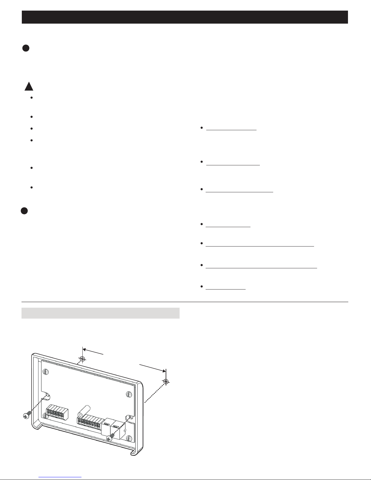
ATTACH THE H32 TO THE WALL
Attach the H32 at the equipment to a solid surface as shown
using the screws and wall anchors supplied.
4-5/16 inches
page 3 of 16
P/N 780101720 3/18 Rev A
Page 4
INSTALLER
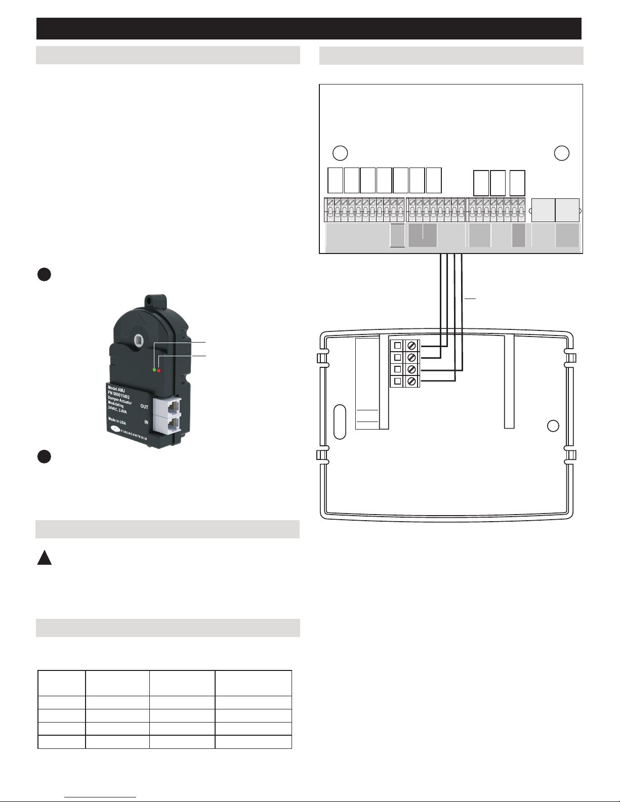
INSTALL UPSTAIRS & DOWNSTAIRS DAMPERS
Install a modulating damper in the duct supplying air to the
upstairs sleeping area and plug one end of the cable into the
connector marked IN on the AMJ actuator and the other end into
the connector marked SLEEP DAMPER on the Wiring Hub. Install a
second modulating damper in the duct supplying air to the
downstairs living area and plug one end of the cable into the
connector on the AMJ actuator marked IN and the other end into
the connector on the Wiring Hub marked LIVING DAMPER. Each
damper uses 2.4VA of power.
When two or more dampers are required to define the upstairs or
downstairs areas, the second damper may be plugged into the
connector marked OUT on the first damper. Up to 6 dampers
can be connected to define an area. LEDS on the damper
actuator indicate when the damper is fully open (green) or fully
closed (red).
Ensure that damper installation does not cause
!
obstruction to the damper blade.
Green LED
Red LED
Wiring Diagram
Wiring Hub Model H32
Relay
RCW/BOY
Relay
Relay
W2/E
G
HVAC
+5V
GND
SB
SA
WIRING HUB
Relay
Y2DSHFR
Relay
ODT
HFR
SENSORS
Relay
ODT
SLP
Relay
SLP
GND
+5VSASB
TSTAT
Relay
Relay
Relay
ERV/HRV
OPN
COM
FR AIR
24V
ERV/HRV
LIVING SLEEP
DAMPER DAMPER
24V
OPN
COM
WH FAN
DAMPR DAMPR
Existing thermostat cable
in replacement installations.
Warning - Only use plug and play cable provided
!
with the Dampers. Additional RJ cables in 25 ft.
lengths with connector PNP25C p/n 580011525) is
available for runs of 50, 75 or 100 feet.
WIRING
!
Warning!
Turn the power to the HVAC equipment off before wiring.
Wiring Thermostat to H32 Wiring Hub
Use the existing thermostat cable to wire the EvenAir
commununicating thermostat to the Wiring Hub.
EvenAir
Terminal
5V
GND
SA
SB
Wire Color
Red
White
Blue
Yellow
Wiring Hub
Terminal
5V
GND
SA
SB
Function
24VAC Power
Common
Signal A
Signal B
T32
Thermostat Model T32 or T32WF
page 4 of 16
P/N 780101720 3/18 Rev A
Page 5
INSTALLER
Wiring H32 to Gas/Electric, 1H/1C
Use 5-conductor, 18 or 20 gage, thermostat cable to wire the
H32 Wiring Hub to the equipment.
H32
Terminal
R
C
W/B
Y
G
Wire Color
Red
Blue
White
Yellow
Green
Equipment
Terminal
R, Rc, Rh
C
W, W1
Y, Y1
G
Function
24VAC Power
Common
Stg1 Heating
Stg1 Cooling
Fan
Wiring H32 to Gas/Electric, 2H/2C
Use 7-conductor, 18 or 20 gage, thermostat cable.
H32
Terminal
R
C
W/B
Y
G
W2/E
Y2
Wire Color
Red
Blue
White
Yellow
Green
Brown
Orange
Equipment
Terminal
R, Rc, Rh
C
W, W1
Y, Y1
G
W2
Y2
Function
24VAC Power
Common
Stg1 Heating
Stg1 Cooling
Fan
Stg2 Heating
Stg2 Cooling
Wiring H32 to Heat Pump, 3H/2C
Wired Sleeping Area Temperature Sensors
Use 2-conductor, 18 or 20 gage, thermostat cable to wire from
the H32 Wiring Hub to the sleeping area temperature sensor.
H32
Wire Color
Terminal
SLP
SLP
HAND
TIGHTEN
White
Red
Printed circuit board
Brass washer
Place wire between brass washer
and the printed circuit board and
hand tighten screw.
The TS51 or TS52 can be installed
in a single gang box or directly to
the wall using the hardware
provided.
Single
Temperature Sensor
Model TS51
Temperature
Sensor
Terminal
SNR
SNR
Temperature Sensors
Model TS52
Temperature
Sensor
FunctionSensor
Thermistor
Thermistor
Dual
Model TS52
Temperature
Sensor
Use 7-conductor, 18 or 20 gage, thermostat cable.
H32
Terminal
R
C
W/B
O
Y
G
W2/E
Y2
Wire Color
Red
Blue
Not Used
White
Yellow
Green
Brown
Orange
Equipment
Terminal
R, Rc, Rh
C
Not Used
O
Y, Y1
G
E/W2
Y2
Function
24VAC Power
Common
Not Used
Reversing Valve
Stg1 Compressor
Fan
Aux Heating
Stg2 Compressor
SLP
SLP
Wiring Hub
H32
SLP
SLP
Wiring Hub
H32
page 5 of 16
P/N 780101720 3/18 Rev A
Page 6

INSTALLER
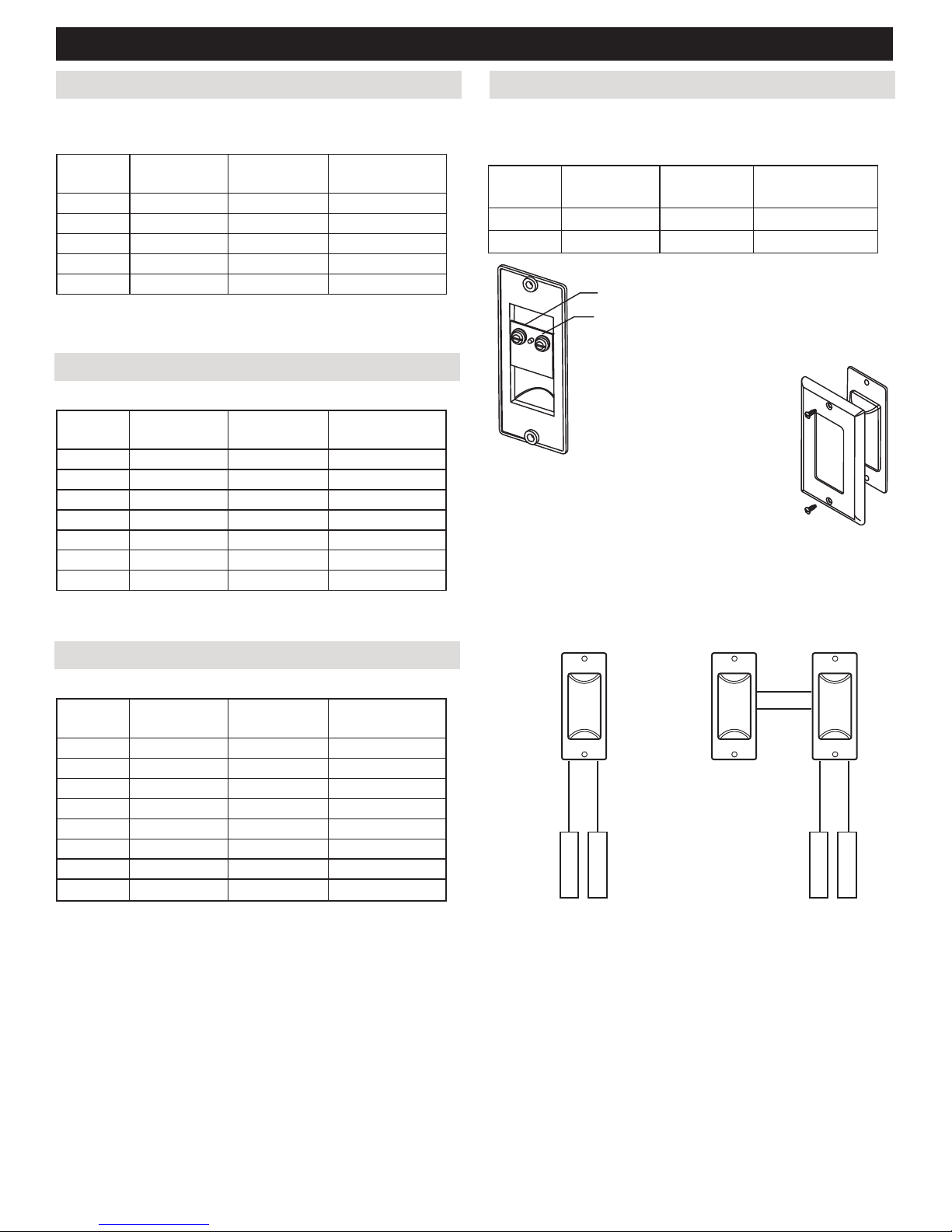
Outdoor Temperature Sensor
The TS3 outdoor temperature sensor is required for dual fuel
heat pumps. The wiring hub automatically switches to fossil fuel
heating when the outdoor temperature drops below the OBP,
Outdoor Balance Point temperature. The temperature limit can
be changed using Installer Option 03 (see T32 or T32WF
manual).
Wall
Wire Nuts
Sensor and
Cover
Gasket
Mounting Plate
Mounting Screws
Screw attaches Cover to Mounting Plate.
USING WIRELESS SENSORS
Before installing the wireless remote temperature sensor, the ER1
Electronic Receiver Module needs to be installed in the Wiring
Hub.
Install the ER1 Electronic Receiver
!
Warning!
Do not turn power on until AFTER the wireless sensors have
been installed and the sensor numbers set, as shown in the
following steps. The Wiring Hub will automatically detect the
electronic receiver and the sensors being used when powered
up.
The ER1 Electronic Receiver plugs into the two 6-pin terminal strips
on the H32 Wiring Hub.
ER1 Electronic Receiver
The outdoor temperature sensor should be placed in a shaded
location and protected from rain or snow such as under the
eves of a home. Select a location and drill a 5/16-inch
diameter hole to pass the sensor wires through.
Use 2-conductor, 18 or 20 gage, thermostat cable to wire
from the H32 Wiring Hub to the outdoor temperature sensor.
H32
Terminal
ODT
ODT
Wire Color
White
Red
Model TS3
Temperature
Wiring Hub
Outdoor
Sensor
ODT
H32
Terminal
SNR
SNR
ODT
FunctionSensor
Thermistor
Thermistor
Wiring Hub.
Install Remote Wireless Sensors
The TSER is wireless and powered by two AA
batteries. Two remote temperature sensors can
be used and the temperatures are averaged. For
a single sensor installation, install the sensor on
an interior wall about 4-feet above the floor and
in a location that best senses the upstairs
sleeping area temperature.
For a dual sensor installation, install the sensors
in locations that will best sense the average
upstairs sleeping area temperature, such as the
master bedroom and the bedroom hallway.
Mount the TSER subbase using the screws
provided.
Install two AA batteries as shown.
page 6 of 16
P/N 780101720 3/18 Rev A
Page 7

INSTALLER
Setting Wireless Sensors as #1 or #2 Using the TSRC Wireless Bedside Control
The TSER is factory set as #0 wireless temperature sensor and
must be set to #1. If two temperature sensors are used, set the
address number on the second sensor to #2. The sensor
location needs to be documented for future reference. Use the
removable labels included with the wireless sensor to identify
the sensors as #1 or #2. Place the labels on the front of the
thermostat over the battery cover.
Press the push button and the LED will blink once, then twice
and repeat this pattern. To set the sensor as the #1 sensor,
release the push button switch after one blink or after two blinks
to set it as #2 sensor. After releasing the push button, the LED
will blink yellow once to indicate successful communication or
blink red indicating that communication was not successful.
The TSRC can be used to turn Econo
Cooling (ECool) On of Off. The TSRC
can be wall mounted or can sit on a
bedside table.
When the Econo Cool mode (ECool) is
turned On, the installed whole house fan
or Economizer will be activated using the
timer or temperature control.
The TSRC is battery powered and
requires no wiring.
Outdoors
Link
Menu
R
Indoors
Cool
ed
Set To
PM
Econo
Cooling
ON
o
F
1 Blink = #1 Sensor
2 Blinks = #2 Sensor
Push Button
Switch
LED Indicator
After setting the sensor number, power can now be applied
!
to the Wiring Hub. The Wiring Hub will automatically detect
the Radio and the sensors being used when powered up.
Selecting a Different Home Number
When two or more wireless EvenAir installations are within 300feet of each other, the EvenAir thermostat and remote wireless
temperature sensors must be set to different Home numbers so
they do not interfere with one another.
EvenAir Thermostat
Use Installer Option 58 in the thermostat installer manual to set
a new Home number.
WIRING DIAGRAMS
The following pages include wiring diagrams and
options for different types of installations:
Wiring Diagram - Installation using wireless temperature
sensors.
Wiring Diagram - Installation using wired temperature
sensors.
Wiring Diagram - Humidifier.
Wiring Diagram - De-Humidification.
Wiring Diagram - Fresh Air Damper.
Wiring Diagram - Whole House Fan
Wiring Diagram - Whole House Ventilation Using Damper
and Equipment Fan
Wiring Diagram - Economizer Using Three Dampers and
Equipment Fan
Remote Wireless Temperature Sensors
Remove one of the batteries to remove power to the sensor.
While pressing the push button switch on the sensor, re-install
the battery. The LED will blink red once, then two rapid blinks,
then three rapid blinks and so on. Release the switch after the
number of blinks corresponding to the Home number to be set.
Changing the Home number does not affect the assignment as
the #1 or #2 sensor (1 to 8).
Remote Wireless Bedside Control
If a TSRC bedside control is used to control the ECool mode
for a whole house fan or economizer, the Home number in the
TSRC must be set to same home number selected in the
thermostat options. (see the TSRC manual).
page 7 of 16
Option - Indoor Fan Vent Mode.
P/N 780101720 3/18 Rev A
Page 8

INSTALLER
Wiring Diagram, Installation Using Battery Powered, Wireless Temperature Sensors
Optional Second
Battery Powered
Wireless Temperature
Sensor
R R
TSER Sensor installed
in Master Bedroom
Battery Powered
Wireless Temperature
Sensor
TSER Sensor installed
in Bedroom Hallway.
Optional TS3 Outdoor
Temperature Sensor
Model TS3
PN 580011306
Temperature Sensor
10K @ 77F
Made in USA
F I E L D
C NO O LT SR
25-foot Plug&Play Cables
Supplied with Dampers.
P&P
2
Modulating
Plug&Play Damper
Sleeping Area Airflow
OUT
IN
Modulating
Plug&Play Damper
Living Area Airflow
OUT
IN
P&P
DWG: 780301206
SA
+5V
GND
R
Upstairs
Airflow %
Auto
Downstairs
Day
Tu
Schedule
AM
EvenAir Thermostat
T32 or T32WF
Required when using
dual fuel heat pumps.
4
Existing thermostat Wires
SB
Heat
Set To
HEAT
Inside
SYSTEM
AUTO
FANMENU MODE
GND
+5V
SA
SB
ER1 Electronic
Receiver Module
Installed in
Wiring Hub
ODT
ODT
R
F IE LD
C NO OLT SR
Model H32
PN 580011202
Wiring Hub
24VAC, 10VA
Made in USA
EvenAir H32 Wiring Hub
Installed at equipment.
Number of wires used in cable.
4
R
C
R
C
W/B W/B
0 0
Y Y
G G
W2/E W2/E
Y2 Y2
HVAC Equipment
page 8 of 16
P/N 780101720 3/18 Rev A
Page 9

INSTALLER
Wiring Diagram, Installation Using Wired Temperature Sensors
Optional Second
Wired Temperature
Sensor
R R
Sensor installed
in Master Bedroom.
See Note 2.
Wired Temperature
Sensor
Sleeping Area Airflow
25-foot Plug&Play Cables
Supplied with Dampers.
22
Sensor installed
in Bedroom Hallway.
See Note 1.
P&P
Modulating
Plug&Play Damper
OUT
IN
Modulating
Plug&Play Damper
Living Area Airflow
DWG: 780301207
Optional TS3 Outdoor
SA
+5V
GND
R
Upstairs
Airflow %
Auto
Downstairs
Day
Tu
Schedule
AM
EvenAir Thermostat
T32 or T32WF
Temperature Sensor
Model TS3
PN 580011306
Temperature Sensor
10K @ 77F
Made in USA
F I E L D
C NO O LT SR
Required when using
dual fuel heat pumps.
4
Existing thermostat Wires
SB
Heat
Set To
HEAT
Inside
SYSTEM
AUTO
FANMENU MODE
2
SLP
ODT
F IE LD
C NO OLT SR
SLP
R
GND
+5V
SA
SB
ODT
Model H32
PN 580011202
Wiring Hub
24VAC, 10VA
Made in USA
EvenAir H32 Wiring Hub
Installed at equipment.
Note 1
Note 2
Use one TS51 sensor for single sensor installations.
Use two TS52 sensors for dual sensor installations.
Number of wires used in cable.
4
OUT
IN
P&P
R
C
W/B W/B
0 0
Y Y
G G
W2/E W2/E
Y2 Y2
R
C
HVAC Equipment
page 9 of 16
P/N 780101720 3/18 Rev A
Page 10

INSTALLER
Wiring Diagram, Humidifier Wiring Diagram, De-Humidification
Dry relay contacts (HFR and HFR) are provided for controlling a
humidifier. A call for humidification is only made during a
heating call if Option 40 is set to On. If Auto RH mode is set to
On using Option 41, the Outdoor Temperature Sensor must be
installed. In Auto mode, the RH setpoint is automatically
decreased at outdoor temperatures below 35F.
Model H32
PN 580011202
Wiring Hub
24VAC, 10VA
Made in USA
F
I
E
L
D
C
O
R
N
T
R
O
L
S
Humidifier
DWG: 780301210
S2000 *
S2020 *
HFR
H
HFR H
* Models S2000 and S2020 are Field Controls humidifier products.
See T32 or T32WF Manual, Installer Options Section
Enable Humidifier Operation
Factory Default: OFF. Range: On or Off.
Select ON if a Humidifier is installed.
Option
NEXT ENTER
Some HVAC equipment is supplied with an input terminal that
forces the equipment fan into low speed to extract more
moisture from the air during cooling calls. The equipment
terminal can be designated as DS, BK, ODD or DHUM. The
Wiring Hub DS terminal is normally 24 VAC and goes to 0VAC
when de-humidification is active. Option 42 turns dehumidification On or Off.
Model H32
PN 580011202
Wiring Hub
24VAC, 10VA
Made in USA
F
I
E
L
D
C
O
R
N
T
R
O
L
S
DS
HVAC Equipment
DS*
* Equipment terminal can be designated DS, BK, ODD or DHUM
See T32 or T32WF Manual, Installer Options Section
Enable De-Humidification
Factory Default: OFF. Range: On or Off.
Select if de-humification is used during
cooling calls.
If de-humidification is On and the humidity is
above the setpoint, the DSBK terminal on the
Wiring Hub will be set to 0VAC to force the
indoor fan to operature at low speed to
remove moisture.
Option
NEXT ENTER
Enable Automatic Adjustment
Factory Default: OFF. Range: On or Off.
If automatic adjustment is set to On, the RH
setpoint will decrease at outdoor temperatures
below 35F. The RH Setpoint is reduced 1% for
each 2F below 35F. Requires Outdoor
temperature sensor be installed.
Option
NEXT ENTER
page 10 of 16
P/N 780101720 3/18 Rev A
Page 11

INSTALLER
Wiring Diagram, Fresh Air Damper
A fresh air damper can be used to meet ASHRAE 62.2
requirements to bring in fresh air each hour. The fresh air
required is first fulfilled during heating and cooling calls. Only if
the fresh air minutes exceed the heating and cooling call, the
indoor fan (G) will be activated and the fresh air damper opened.
Options 20 to 25 control fresh air operation.
F IE LD
C NO OLT SR
R
FR AIR
DAMPER
Red
24V
White
COM
Blue
OPN
Fresh Air Damper
Model H32
PN 580011202
Wiring Hub
24VAC, 10VA
Made in USA
See T32 or T32WF Manual, Installer Options Section
Indoor Fan Vent Mode
The indoor fan VENT mode circulates air within the home between
heating and cooling calls. If VENT mode is enabled in Option 25
and the homeowner has selected fan VENT mode, the fan will be
activated for 15 minutes when no heating or cooling call has
occurred in the last 120 minutes.
Vent mode will be automatically turned Off if Fresh Air Operation
DWG: 780301208
is selected using Option 20 or if Whole House Fan or Economizer
operation is selected using Options 30 or 31.
Enable VENT Mode Operation
Factory Default: OFF. Range: On or Off.
Select ON to enable Fan VENT mode.
Option
NEXT ENTER
Enable Fresh Air Control
Factory Default: OFF. Range: On or Off.
Select ON to enable Fresh Air Control. Fresh
air damper opens and an optional ERV or
HRV is activated.
Set Fresh Air Minutes/Hour
Factory Default: 30 minutes. Range: 0 to 60.
Select the number of minutes the fresh air
damper should open each hour based on
ASHRAE 62.2 calculations and the damper
size.
Enable Severe Weather Limit
Factory Default: OFF. Range: On or Off.
Select ON to inhibit fresh air intake using
outdoor temperature limits set in options
23 and 24.
Set High Temperature Limit
Factory Default: 95F. Range: 65F to 100F.
Select the maximum outdoor temperature for
fresh air damper operation.
Option
NEXT ENTER
Option
NEXT ENTER
Option
NEXT ENTER
Option
Set Low Temperature Limit
Factory Default: 35F. Range: 0F to 65F.
Select the minimum outdoor temperature
for fresh air damper operation.
Option
NEXT
NEXT
ENTER
ENTER
page 11 of 16
P/N 780101720 3/18 Rev A
Page 12

INSTALLER
Wiring Diagram, Whole House Fan
A relay (White Rogers 90-370) can in installed within the
electrical box on the whole house fan and controlled by the
Wiring Hub. The Wiring Hub applies 24 VAC to the OPN
terminal that activates the external relay that controls line
voltage to the whole house fan. The whole house fan can be
timer or temperature controlled using the Options below.
Windows must be open to allow outdoor air to enter
!
the home.
!
Warning!
Turn power off before wiring. The relay must be installed within
a UL conforming electrical enclosure to prevent electrical shock.
Line Voltage
Neutral
Line Voltage
Hot
Whole
House
Fan
Model H32
PN 580011202
Wiring Hub
24VAC, 10VA
Made in USA
F IE LD
C NO OLT SR
R
WH FAN
DAMPER
24V
COM
OPN
Relay 90-370
1,3 24VAC Coil
4,6 Common
5 NC
2 NO
1
3
5
2
6
4
FC P/N: 510900300
Wiring Diagram, Whole House Ventilation
Using Damper and Equipment Fan
A damper can be installed on the supply air plenum and the
equipment fan is used to bring cool outdoor air into the home and
exhaust the return air into the attic. When the ECool mode is
selected the damper opens and the equipment fan is activated
based on temperatures or a built-in timer.
Windows must be open to allow outdoor air to enter
!
the home.
F IE LD
C NO OLT SR
R
WH FAN
DAMPER
Red
24V
White
COM
Blue
OPN
Supply Plenum
Damper
Option
NEXT ENTER
Model H32
PN 580011202
Wiring Hub
24VAC, 10VA
Made in USA
DWG: 780301212
Enable Free Cooling using Damper and Equipment Fan
Factory Default: OFF. Range: On or Off.
Select if dampers and the equipment fan is
used to bring in cool outdoor air for cooling.
See the Wiring Hub Installation for different
economizer configurations.
DWG: 780301211
Enable Free Cooling using Whole House Fan
Factory Default: OFF. Range: On or Off.
Select ON if a whole house fan is controlled
by the thermostat.
Whole House Fan controlled by Temperature
Factory Default: OFF. Range: On or Off.
Select ON to control the Whole House Fan
using the outdoor, room and cooling
setpoint temperatures.
Whole House Fan Outdoor Temperature Limit
Factory Default: 0. Range: 0-10 degrees.
Select the number of degrees the outdoor
temperature must be below the room
temperature to activate the Economizer or
Whole House Fan.
Whole House Fan Control by Timer
Factory Default: OFF. Range: On or Off.
Select ON to control Whole House Fan or
Economizer using a 1 to 12 hour timer set
in the thermostat by the homeowner using
the User Menu. The timer starts when the
System is switched to ECool. When the
timer expires, the System is set to Off.
Option
Option
Option
Option
NEXT ENTER
NEXT
NEXT
NEXT
ENTER
ENTER
ENTER
page 12 of 16
Damper and Fan controlled by Temperature
Factory Default: OFF. Range: On or Off.
Select ON to control the Whole House Fan
using the outdoor, room and cooling setpoint
temperatures.
Option
NEXT
Damper and Fan Outdoor Temperature Limit
Factory Default: 0. Range: 0-10 degrees.
Select the number of degrees the outdoor
temperature must be below the room
temperature to activate the Economizer or
Whole House Fan.
Option
NEXT
Damper and Fan Control by Timer
Factory Default: OFF. Range: On or Off.
Select ON to control Whole House Fan or
Economizer using a 1 to 12 hour timer set in
the thermostat by the homeowner using the
User Menu. The timer starts when the System
is switched to ECool. When the timer expires,
the System is set to Off.
P/N 780101720 3/18 Rev A
Option
NEXT
ENTER
ENTER
ENTER
Page 13

INSTALLER
Wiring Diagram, Economizer Using Three Dampers and Equipment Fan
Three dampers can be installed to provide
Economizer cooling using the equipment
fan. In compressor cooling, the Exhaust
Air and the Outdoor Air Intake Dampers
are closed and the Return Air Damper is
Wiring Hub
24VAC, 10VA
Made in USA
Model H32
PN 580011202
WH FAN
DAMPER
F IE LD
24V
C NO OLT SR
R
COM
OPN
open.
When the system is in ECool and the
Economizer is activated, the Outdoor Air
Intake and Exhaust Air Dampers open, the
Return Air Damper closes and the
equipment fan is activated. Windows do
not have to be open because outdoor air
FC P/N: 510900300
is drawn in thru the Outdoor Air Intake
Damper.
In Compressor In Economizer
Cooling Cooling
Relay terminal NC
Relay terminal NO
24VAC
0VAC
Enable Free Cooling using Dampers and Equipment Fan
Factory Default: OFF. Range: On or Off.
Select if dampers and the equipment fan is
used to bring in cool outdoor air for cooling.
See the Wiring Hub Installation for different
economizer configurations.
Option
NEXT ENTER
Red
White
Blue
1
3
5
6
2
4
Relay 90-370
1,3 24VAC Coil
4,6 Common
5 NC
2 NO
0VAC
24VAC
NC
NO
Red
White
Blue
Outdoor Air Intake Damper
Red
White
Blue
DWG: 780301209
Dampers and Fan controlled by Temperature
Factory Default: OFF. Range: On or Off.
Select ON to control the Whole House Fan
using the outdoor, room and cooling setpoint
temperatures.
Option
Dampers and Fan Outdoor Temperature Limit
Factory Default: 0. Range: 0-10 degrees.
Select the number of degrees the outdoor
temperature must be below the room
temperature to activate the Economizer or
Whole House Fan.
Option
Dampers and Fan Control by Timer
Factory Default: OFF. Range: On or Off.
Select ON to control Whole House Fan or
Economizer using a 1 to 12 hour timer set in the
thermostat by the homeowner using the User
Menu. The timer starts when the System is
switched to ECool. When the timer expires, the
System is set to Off.
Option
NEXT ENTER
NEXT ENTER
NEXT ENTER
Red
White
Blue
Exhaust Air Damper
Return Air Damper
page 13 of 16
P/N 780101720 3/18 Rev A
Page 14

MAINTENANCE AND TROUBLESHOOTING
THERMOSTAT OPERATION
Problem - nC is displayed on thermostat.
nC is displayed on the thermostat when the thermostat loses
communication with the wiring hub. If the message continues
to be displayed, turn the system off and check the wiring
between the thermostat and wiring hub.
DAMPER OPERATION
Problem - No airflow to the sleeping area AND living
area registers
Turn system off immediately. Both dampers may be connected
backwards at the wiring hub or at the damper actuator (causing
dampers to close rather than open).
Problem - No airflow to the sleeping area OR living
area registers
Turn system off. One of the dampers may be connected
backwards at the wiring hub or at the damper actuator
(causing a damper to close rather than open).
Problem - Limited airflow to the sleeping area OR living
area registers
Turn system off. The damper blade movement may be inhibited.
To verify a damper blade moves freely, remove the two
mounting screws on the actuator. Do not disconnect the plug
and play cables. Verify the damper blade spins 360 . If the blade
spins freely, reattach the actuator to the damper by aligning the
keyed shaft. If the blade does not spin freely, examine the
damper for obstruction or damage and replace the damper if
necessary.
o
SENSOR INSTALLATION
Problem - nS message on thermostat.
For wired sensors, check that the sensor is wired correctly.
Check for a short in the sensor wiring. For wireless sensors,
check that batteries are installed in the sensor and that the
sensor numbers are set correctly.
Problem - Err 01 or Err 02 message on thermostat.
Check the batteries in the wireless sensor and that the
sensor numbers are set correctly.
Problem - Sleeping area temperature reading very high or
very low.
Check that the correct sensor(s) have been used. One
wired TS51 sensor is used in a single sensor installation.
Two TS52 sensors are used in a dual sensor installation.
Problem - When directing airflow to the sleeping area, the
airflow is actually directed to the living area, and when
directing the airflow to the living area, the airflow is actually
directed to the sleeping area.
Turn system off. Check if the dampers are switched (sleeping
area damper is connected to the living area connector and the
living area damper is connected to the sleeping area connector.)
COMFORT CONCERNS
Problem - Downstairs bedroom is too cold or too hot at night.
The Nighttime Airflow Control option directs more airflow to the
sleeping area and less airflow to the unoccupied living area. If
the downstairs bedroom is on the same HVAC trunk as the
living area, the downstairs bedroom may become uncomfortable
at night. Turn off the Nighttime Airflow Control option using the
User Options.
Problem - The room temperature on the thermostat seems
too high or too low.
The thermostat is factory calibrated within 1 degree.
However, if a homeowner finds the temperature “feels”
too high or too low, the thermostat can be calibrated to
what the homeowner feels is the correct temperature using
Installer option 15 for the living area and option 16 for
the sleeping area.
page 14 of 16
P/N 780101720 3/18 Rev A
Page 15

Field Controls
Part Number
580011106
580011107
580011201
580011301
580011302
580011305
580011205
580011306
580011410
580011402
580011510
580011525
580011405
580011406
510900300
Model
Number
T32
T32WF
H32
TS51
TS52
TSER
ER1
TS3
TSRC
AMJ
PNP25
PNP25C
IS
DS
MDP-#
MDP-LxH
370R
SPARE PARTS AND ACCESSORY LIST
Description
Programmable, communicating thermostat w/ airflow control, for all equipment.
Programmable, communicating thermostat w/ airflow control for all equipment.
WiFi enabled.
Wiring Hub for gas/electric, conventional or dual fuel heat pump equipment with 3 Heat/2 Cool
Wired temperature sensor for the sleep area. Single sensor installation.
Wired temperature sensor for the sleep area. Dual sensor installation.
Wireless temperature sensor for the sleep area. Single or Dual sensor installation. Requires ER1.
Electronic receiver module. Required when using wireless sensors.
Outdoor temperature sensor. Required for dual fuel heat pumps.
Wireless remote control/temperature sensor. Requires ER1.
Replacement modulating actuator control, plug and play connectors.
Replacement 25 ft. RJ cable.
Additional 25 ft. RJ cable and connector.
Replacement idler shaft for AMT and AMJ actuators.
Replacement drive shaft for AMT and AMJ actuators.
EvenAir Round Balance Damper, Plug and Play. Sizes - 4” - 20” diameter.
EvenAir Rectangular Balance Damper, Plug and Play. Sizes - 8”, 10” and 12” Heights, up to 24” Length.
Relay, 24VAC Control, 250VAC Line, SPDT 90-370
page 15 of 16
P/N 780101720 3/18 Rev A
Page 16

This manual may be downloaded and printed from the Field Controls website (www.fieldcontrols.com)
WARRANTY
For warranty information about this or any Field Controls product, visit:
www.fieldcontrols.com
Field Controls Technical Support
1.800.742.8368
fieldtec@fieldcontrols.com
Field Controls Customer Service
1.252.522.3031
sales@fieldcontrols.com
9154 Stellar Ct
Phone: 252.522.3031 Fax: 252.522.0214
Corona, CA 92883
c
Field Controls, LLC
www.fieldcontrols.com
2630 Airport Road
Kinston, NC 28504
P/N 780101720 3/18 Rev A
 Loading...