

Page 1
This service bulletin describes the steps that may be necessary to replace your existing Model
Field Controls Humidifiers
AN-137 Replacement Instructions for
Models ESU14 & ESU20
SUPPLEMENT TO THE ELECTRONIC STEAM
POWER HUMIDIFIERS MODEL #S2000 AND S2020
P/N 090376A0137 REV. D 10/2011 Copyright © 2011, Field Controls Inc., All Rights Reserved
Field Controls Inc. 2630 Airport Road Kinston, NC 28504 PH: 252.522.3031 FAX: 252.522.0214
ESU14 or ESU20 Steam Humidifier, with the new Model S2000 or S2020 Power Steam
Humidifier. The new “S” models have been redesigned and improved. There are some differences
which must be taken into account when installing this unit or replacing an older model.
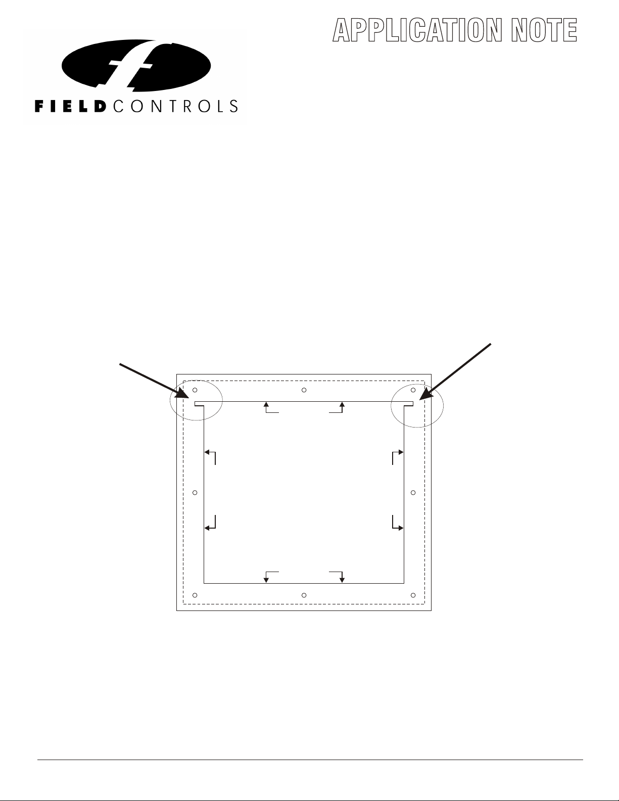
1. MOUNTING - First and most important is the mounting of the new humidifier. The new
model has a larger reservoir but measures the same width and height as the old “ESU”. The
reservoir protrudes deeper into the duct and occupies more space inside the duct. The new
“Under Duct Mounting Flange” is an integral part of the reservoir. As a result, the modification
to perform when mounting the new S2000 or S2020, is to snip and lengthen the flange dimension
on your existing reservoir cutout opening in the warm air supply plenum.
CUT ON LINE
MOUNTING TEMPLATE
MODEL S2000 & S2020
CUT ON LINE
1. TAPE TEMPLATE IN LEVEL POSITION.
2. DRILL (8) HOLES FOR SHEET METAL SCREWS
SHOWN ON TEMPLATE (DO NOT DRILL LARGER
THAN 1/8" DIAMETER.
3. CUT OUT SOLID LINE AREA AS MARKED.
4. MOUNT HUMIDIFIER PER INSTRUCTIONS.
CUT ON LINE
P/N 094021B0037
CUT ON LINE
FIG. 4
With this modification done, you should be able to insert the new humidifier into the cutout
opening and secure the unit with the 8 self tapping screws provided. The hole dimensions on
the front plate have not changed and should match up. If necessary, locally reinforce the opening
with sheet metal sleeves to insure that the unit will remain level and not sag with the added
weight of the water.
A 2nd template is included with the “S” series humidifiers for mounting the unit under the duct
on the return or cold air side of the furnace. Note that there is no need to order an under the duct
mounting kit, due to the new integrated mounting flange.
1
Page 2
2. WIRING - Another important difference in the replacement of an “ESU” model with a new “S”
Field Controls Humidifiers
AN-137 Replacement Instructions for
Models ESU14 & ESU20
SUPPLEMENT TO THE ELECTRONIC STEAM
POWER HUMIDIFIERS MODEL #S2000 AND S2020
P/N 090376A0137 REV. D 10/2011 Copyright © 2011, Field Controls Inc., All Rights Reserved
Field Controls Inc. 2630 Airport Road Kinston, NC 28504 PH: 252.522.3031 FAX: 252.522.0214
series humidifier is the wiring connections. On the “ESU” the humidity control was connected to the
two ‘WHITE” wires on the molded plug. When upgrading to the “S” series, simply cut the two
white wires and connect them to the two “H” terminals on the top of the front cover.
The blower (fan) interlock was connected via the two red wires on the old “ESU” model and usually
incorporated a field installed transformer and interlocking relay. Just cut the two red wires and
connect them to the “R” and “G2” terminals on the top of the front cover. In this method you can
reuse the field relay and transformer which were originally installed with the ESU.
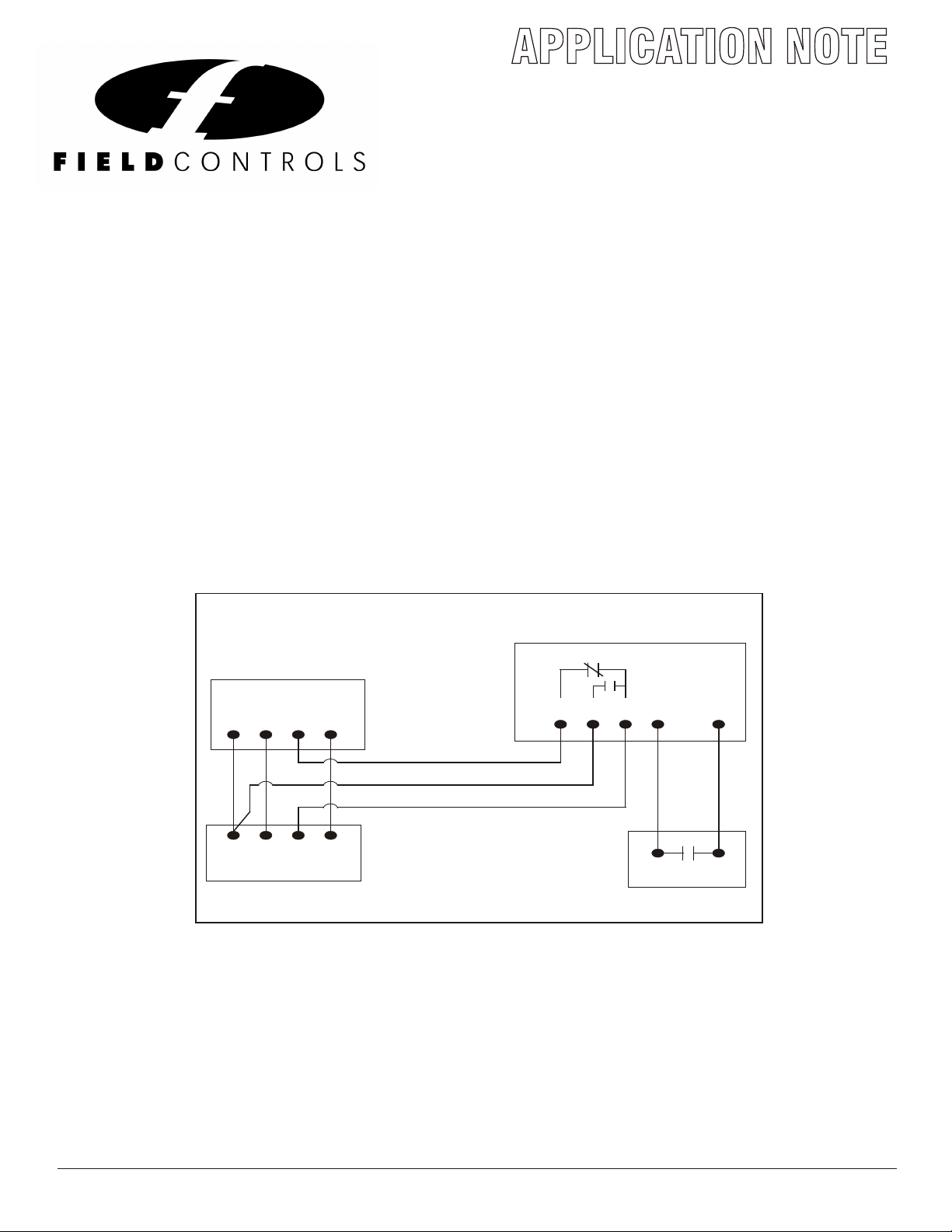
If this is a new install then you can fully utilize the on board relay provided with the “S” series
humidifier and interlock your blower “fan” by following the low voltage diagram. There is no need
to install a separate transformer or relay.
S2000 & S2020 T ypical W ir i ng
and Bl ower I nter lock Di agr am
S2000 & S2020 Humidifier
Typical
Thermostat
G YWR
G1 R G2 H H
G YWR
Furnace
H eat & Cool System
Humidistat
DO NOT plug the molex connector from the old “ESU” humidifier, into the socket on the side of
the front cover on the new “S” series humidifier. That socket connection is now reserved for the
automatic drain valve only. Doing so will damage the unit and void the warranty.
2
Page 3

3. DRAINS - It is still necessary to run an overflow drain line from the humidifier to a suitable
Field Controls Humidifiers
AN-137 Replacement Instructions for
Models ESU14 & ESU20
SUPPLEMENT TO THE ELECTRONIC STEAM
POWER HUMIDIFIERS MODEL #S2000 AND S2020
P/N 090376A0137 REV. D 10/2011 Copyright © 2011, Field Controls Inc., All Rights Reserved
Field Controls Inc. 2630 Airport Road Kinston, NC 28504 PH: 252.522.3031 FAX: 252.522.0214
drain. Now, it is also required to run an additional drain line from the new automatic drain valve
to a suitable drain.
The new “S” series humidifiers have an automatic drain valve which will drain the tank every 12
hours, to minimize chemical buildup inside the tank. The water is allowed to cool down to 140
degrees F. before the water is drained out.
The humidifier drains by gravity only, so it must be mounted at a sufficient height to allow for
proper drainage. DO NOT route the drain hoses above the level of the humidifier, and watch for
kinks or cuts in the hoses.
If you have a basement installation and require draining into a condensate pump, we recommend
a Beckett Model # CU451ULHT or CU551ULHT. These pumps are rated for high temperature
water and have built in check valves.
4.WATER - The frequency which the water fill solenoid on the new steam unit will activate can
exceed the older model. This more frequent filling of the tank may be noticeable in the form of
water hammer noise or spikes in the water line. Install an optional water hammer arrester
#WH-100, and the noise will dissipate.
If this Engineering notice does not cover a question or issue that you have encountered during
your installation or replacement project, please contact the Technical Support Hotline @
1-800-446-3110.
3
 Loading...