

Page 1

INSTALLATION INSTRUCTION
THE FIELD CONTROLS COMPANY
DRAFT REGULATORS (3"-10")
TYPES B34, AND DR
READ CAREFULLY
LISTED UNDER RE-EXAMINATION SERVICE OF UNDERWRITERS LABORATORIES INC. LISTED UNDER LABEL SERVICE OF CANADIAN STANDARDS ASSOCIATION.
NOT CSA CERTIFIED FOR SOLID FUELS.
The regulator contained in this package is manufactured with careful precision. It is designed to
regulate chimney draft with a high degree of accuracy and fuel efficiency. The control may be
marked B-34 or DR. The basic draft adjustments are similar, but where variations apply, the
following paragraphs will explain the procedure.
Proper operation of the regulator depends upon proper installation and adjustment. Use a CO2
indicator, stack thermometer and draft gauge to adjust oil or solid fuel burners. Domestic oil
burners work best with the draft over fire of .01 to .02-inches W.C.
Solid fuel burners work best with over-fire draft of .04 to .08. Excessively high draft settings
over the fire create smokey fires and pulsation.
Step 1 Weight assembly must be attached to
damper prior to its installation in flue
pipe, refer to appropriate illustration
below.
Step 2 LOCATION OF DRAFT CONTROL (See Figs.
3-8)
Locate the draft control as near to the
furnace or boiler as possible. If the
installation has a smoke pipe stack control,
locate the regulator at least 18" away from
the stack control.
BEST LOCATIONS FOR
OIL OR SOLID FUELS
*Selected sizes CSA and UL
approved.Not
CSA certified for
solid fuels.
NOTE: Damper must be mounted
with the hinge pins horizontal
and the face of the damper
plumb for correct operation.
This is done by rotating the
damper section within the
collar for any pipe position.
Step 3 BALANCING WEIGHT ASSEMBLY AND DRAFT ADJUSTMENT
as shown in Fig. 1.
TYPE B-34 (See Fig. 1)
Assemble the "counter balance weight assembly" to the
draft control as shown in Fig. 1.Thread "counter balance
weight" through "threaded nut" attached to the vane.
Assemble"hex nut" and "knurled nut" on front of vane.
Tighten screws to hold firmly
in place.
Turn "knurled nut" counter clockwise for less draft, clockwise for more draft.
When adjustment is made for desired draft, lock the "counter balance weight assembly" in place
by tightening the "hex nut"" located under the "knurled nut" against the vane.
Page 2
TYPE DR (See Fig. 2)
Assemble the "carriage bolt" through the "weight support bracket" attached to vane.
Thread tapered "counter balance weight" on "carriage bolt" (tapered portion of weight must point
toward bottom of draft control). For less draft, slide "counter balance weight assembly" toward
"Low" position marked on the bracket; for more draft, slide "counter balance weight assembly"
toward "Hi" position.
When adjustment is made for desired draft, tighten weight securely to "carriage bolt". VERTICAL
INSTALLATION: The 8" and 9" sizes, when mounted in vertical installations ONLY, require a small
screw and nut (supplied) assembled in the hole at the bottom vane. The 6" and 7" regulators do not
require this additional hardware in a vertical installation.
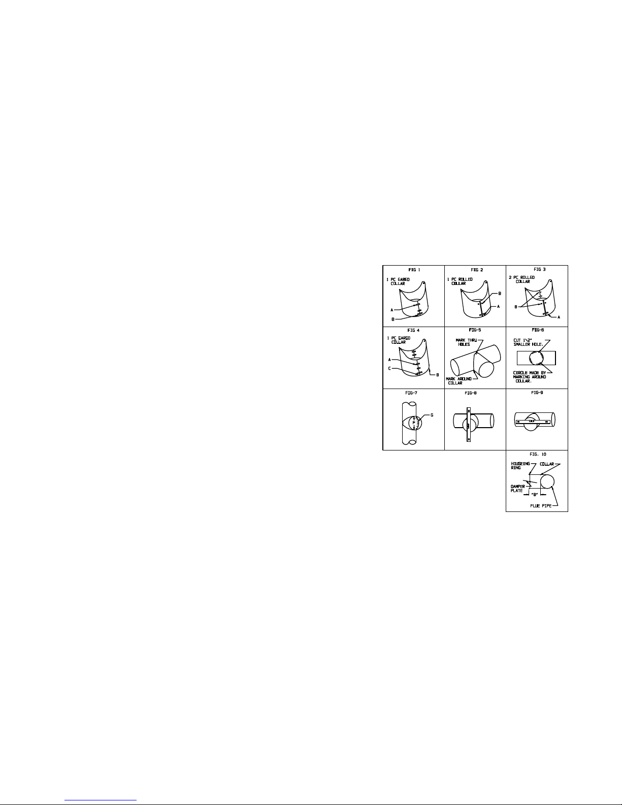
Directions for Assembly/Installation of Collar
READ CAREFULLY - DON'T GUESS
If draft regulator is purchased without a collar or a tee joint, the depth "B" of the collar (Fig.
10) or the stub of the tee joint used must be of adequate length to avoid the damper plate entering
the flue pipe - preventing flow interference.See Fig. 10 below.
ONE-PIECE EARED COLLAR - (Fig. 1) Supplied
W/3"-5" B34
- Hook tongues "A" together to form a round collar.
- Pull the assembled collar outward until the tongues are
seated in the slots and recess.
- With the tongues recessed, flatten tongues with a pair of
pliers.Bend the tip of each tongue into the open slot, thus
entirely closing the slot opening.
- Now bend the lugs "B" outward at a 90o angle. Insert bolt
through lugs and place nut on it.
- Proceed with instructions starting at paragraph 2 (a)
below under "TWO-PIECE EARED COLLAR".
ONE-PIECE ROLLED COLLAR - (Fig. 2) Supplied
W/6" & 7" B34 & DR
- Bend the lugs "A"" outward at 90o angle.
- Simply align the holes "B" toward the back of the collar
and bolt together.
- Insert bolt through lugs "A", place a nut on it, but do
not tighten until the damper section is in place.
- Proceed with instructions starting at paragraph 2 (a)
below under"TWO-PIECE EARED COLLAR".
TWO-PIECE ROLLED COLLAR - (Fig. 3) Supplied
W/8" & 9" B34 & DR
- Bend the lugs "A" outward at 90o angle.Simply align the
holes"B"in the two collar halves and bolt together with the
hardware supplied.
- Insert longer bolt through lugs "A"place nut on it but do
not tighten until the damper section is in place.
- Proceed with instructions starting at paragraph 2 (a)
below under "TWO-PIECE EARED COLLAR".
Page 3

TWO-PIECE EARED COLLAR - (Fig. 4) Supplied W/10" B34
(a) Carefully form each half of Collar (B). Fig. 4, into a half circle and hook tongues "A" into
the slots as shown.Bend the tongues "A" down almost flat; then pull the halves "B" outward until the
tongues seat in the slots - and recess. It is important that this be done because the Collar will be
too small if you fail to seat the tongues.Then flatten the tongues with a pair of pliers, bending the
tip of each tongue "A" down into the open slot end,thus entirely closing the slot opening.
(b) Bend the lugs "C" outward at 90o angle.Insert the bolt through the holes and place nut on it
but do not tighten until the damper section is in place.
2. (a) AFTER FABRICATING COLLAR COMPLETELY, place tabbed ends tightly against pipe, as shown in
Fig. 5, so that open end of Collar faces outward. Mark through holes in tabs and drill or punch for
metal screws. If holes are drilled about 1/16" toward back of pipe, this will assure that when
Collar is fastened in place, it will be pulled firmly against pipe to make a good,tight joint.
(b) After fastening Collar to pipe, mark around outside of Collar, Fig. 5.
3. (a) Take the Collar off and inscribe a circle inside the one just marked and about 1/2" apart as
shown in Fig. 6,then cut out the inside circle, leaving opening "F", Fig. 7.
4. (a) Snip from edge of hold to outside circle in a series of slits approximately 1/2"apart as
shown in "G", Fig. 7.
(b) Now fasten Collar back in place, Fig. 7, with metal screws and bend tabs "G", Fig. 7, outward
against Collar to make a tight joint.
5.Figures 8 and 9 show method of checking Damper for "plumb" and hinge pins for "horizontal" after
Damper is installed.This is important for proper draft control operation.
THE FIELD CONTROLS COMPANY
2308 AIRPORT ROAD
KINSTON, NORTH CAROLINA 28501-8947 (919) 522-3031
P/N 46001000 REV. A
 Loading...