

Page 1
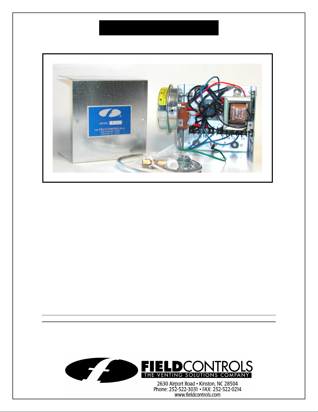
SYSTEM CONTROL KIT
Model: CK-81
Designed for use with the SWG Series Power Venter for controlling 750 millivolt controlled Natural
and L.P. Gas appliances with a 24AC voltage thermostat or wall switch, such as a gas fireplace.
NOTE:
is recommended. Manual operation controls to gas valve must be rendered inoperative.
The use of flue gas spillage switches such as The Field Controls Model GSK-3, or equivalent,
I
TEMS INCLUDED IN KIT:
1) Junction box with mounted pressure switch
1) 1 ft. length of 1/8 inch aluminum tubing
1) 1/8" tubing connector
1) 1/8" tubing to 1/8" NPT elbow
1) Flexible conduit connector
1) Mounted 115 VAC/24 VAC transformer
1) Mounted post-purge timer (non-adjustable)
DO NOT DESTROY
THESE INSTRUCTIONS MUST REMAIN WITH EQUIPMENT
Page 2
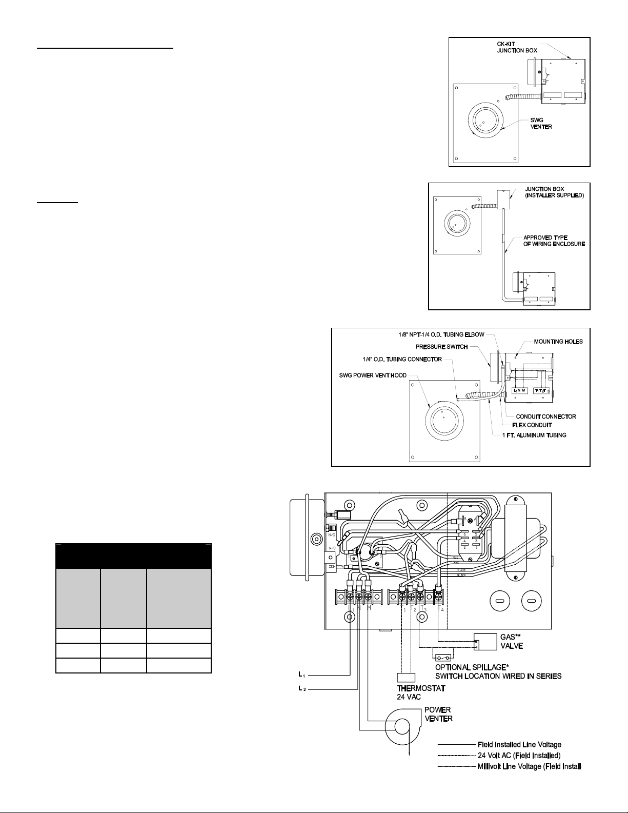
MOUNTING JUNCTION BOX
The junction box can be mounted at the venter or remotely mounted away from the
venter. (See Figures 1 & 2)
1. Remove one of the knockouts from the side of the junction box where the pressure
switch is mounted. Install the flexible conduit connector onto the CK-81 junction box
and secure with fastening nut. If remote mounting the CK-81 junction box, mount
the flexible conduit connector onto a 2" x 4" installer supplied junction box.
2. Fasten the flexible conduit from the SWG Venter into the conduit connector. Mount
the CK-81 junction box or installer supplied junction box onto the wall or floor joist
without straining the flexible conduit. Fasten the CK-81 junction box through the
four dimpled locations on the base of the box. (See Figure 3)
Figure 1
WIRING
(See Figure 4 and Table 1)
Wire the venter motor and controls in accordance with the National Electrical
Code, manufacturer's recommendations and/or applicable local codes. UNITS
MUST BE GROUNDED. Check ground circuit to make certain that the unit has
been properly grounded. The wiring should be protected by an over-current circuit
device rated at 15 amperes. CAUTION must be taken to ensure that the wiring
does not come into contact with any heat source. All line voltage and safety control
circuits between the venter and the appliance MUST be wired in accordance with
the National Electrical Code for Class I wiring or equivalent methods.
1. Route the venter motor and control wiring with an appropriate wiring method.
2. All wiring to be Class I or equivalent for line voltage or
safety control circuits.
3. All manual operation controls to gas valve must be
rendered inoperative.
S
EQUENCE OF OPERATION
1. Thermostat calls for heat. The relay closes and the
power venter energizes.
2. After motor is up to speed, the pressure switch closes
and the gas valve energizes.
3. When the thermostat is satisfied, the thermostat opens
and stops the gas valve operation. The postpurge timer in the CK-81 will cause operation of
the venter motor for an additional period of
approximately one to three minutes.
Figure 2
Figure 3
Table 1
WIRE LENGTH FOR 750
MILLIVOLT WIRING
Max.
Wire
Sizes
Length
(2-wire
cable)
No. 18 30 ft. 60 ft.
No. 16 50 ft. 100 ft.
No. 14 80 ft. 160 ft.
Max.
Combined
Length
(2 single
wires)
*Floor furnace application must use
a gsk-3 spillage sensing switch.
**(Optional connections), connect to millivolt
thermostat connections on heating equipment.
Page 2
Figure 4
Page 3

PRESSURE SWITCH SENSING TUBE INSTALLATION
1. Attach the 1/4 inch tubing connector to the pressure tube on the SWG Venter. (See Figure 3)
2. Connect the supplied 1/4" aluminum tubing to the tubing connector. Route the tubing to the CK-81 junction box and
connect the tubing to the pressure switch. When routing the tubing, avoid kinking the tubing by bending the tubing too
sharply.
NOTE: For remote mounted CK-81 Junction Box, use 1/4" OD copper, aluminum or plastic tubing, and route the tubing to
avoid contact with any heat source.
Refer to the SWG Venter installation instructions for setting system airflow.
PRESSURE SWITCH ADJUSTMENTS
With the venter airflow set and the appliance operating
at the best operating efficiency adjust the pressure
switch by rotating the adjustment screw clockwise until
the burner shuts off, then rotate the adjustment screw
counterclockwise until the burner fires. Rotate the
adjustment screw an additional 1/4 turn
counterclockwise to ensure proper switch setting. (See
Figure 5)
SYSTEM CONTROL CHECK OUT PROCEDURES
1. Adjust the thermostat to call for heat and observe
the power venting system for proper operating
sequence. (Repeat if necessary).
a. Thermostat or wall switch calls for heat.
b. Venter motor starts.
Figure 5
c. Pressure switch closes and burner starts.
d. Thermostat is satisfied or wall switch is turned off. The burner stops; the venter runs for 1-3 minutes longer.
2. While system is operating disconnect power to the venter motor. This should open the pressure switch contacts and
stop burner operation.
TROUBLE SHOOTING HINTS
1. Main burner does not fire when thermostat or wall switch calls for heat with venter operating.
a. Check pressure switch adjustment.
b. Check wiring connections between pressure switch and burner.
c. Check pressure switch for continuity across terminals, during venter operation.
2. Venter does not activate when thermostat or wall switch calls for heat.
a. Check wiring.
3. Flue gas odor.
a. Check system draft.
b. Check for negative pressure in building.
MAINTENANCE
1. Motor: Inspect motor once a year, the motor should rotate freely.
2. Wheel: Inspect venter wheel annually to clear any soot, ash or coating which inhibits either rotation or air flow.
Remove all foreign material before operating.
3. Vent System: Inspect all vent pipe connections annually for looseness and for evidence of flue gas leakage. Seal or
tighten pipe connections if necessary.
Page 3
Page 4

INSTALLATION INFORMATION
MODEL NO.:____________________________________________________________
CK-81
INSTALLER'S NAME:_____________________________________________________
INSTALLER'S COMPANY: _________________________________________________
INSTALLER'S PHONE NO.: ________________________________________________
DATE OF INSTALLATION:_________________________________________________
Page 4
P/N 46161700 Rev B 06/04
 Loading...