

Page 1
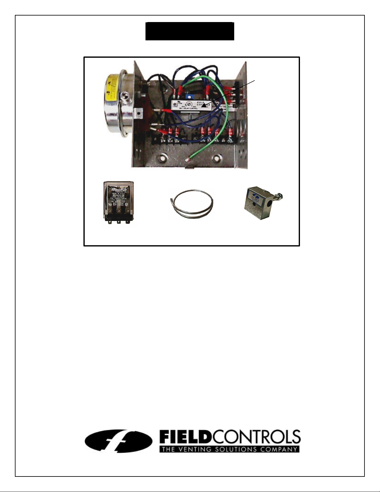
CONTROL KIT
P/N 46126600
P/N 46144700
Model: CK-65
Timer
Relay
Aluminum Tubing
WMO-1 Safety Kit
P/N 46086901
Designed for controlling oil fired heating appliances using a
Honeywell R8184G or equivalent Primary Control. The control
operates the burner motor and the power venter together. A
solenoid valve is used to control burner operation.
ITEMS INCLUDED IN KIT:
1 - Junction box with mounted pressure switch and and solid state post
purge control
1 - WMO-1 Secondary Safety Switch
1 - Delay oil solenoid valve with preset pre-purge
1 - 2 ft. length of 1/4 inch aluminum tubing
2 - Flexible conduit connector
1 - 1/4 inch tubing connector
2630 Airport Road • Kinston, NC 28504
Phone: 252-522-3031 • FAX: 252-522-0214
www.fieldcontrols.com
Page 2
INSTALLATION AND ADJUSTMENTS
Figure 2
ure 1
Figure 3
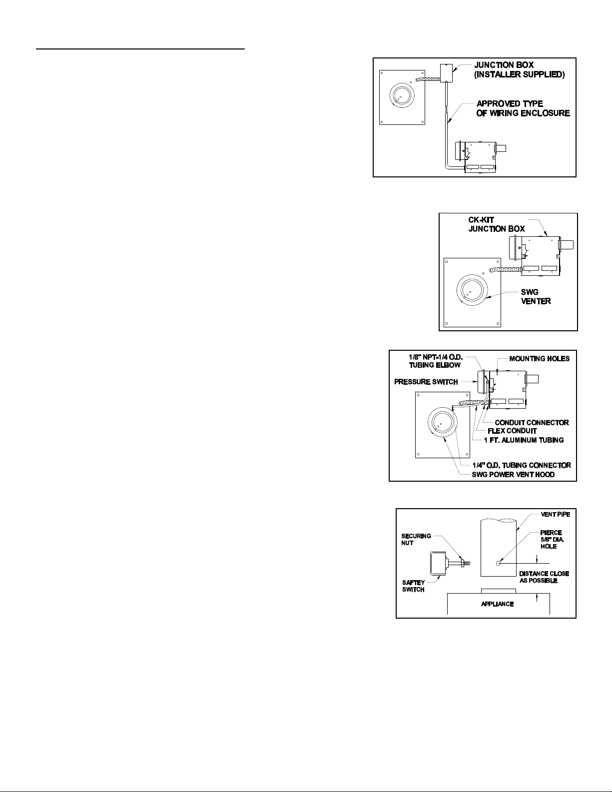
MOUNTING JUNCTION BOX:
The junction box can be mounted at the venter or remotely
mounted away from the venter. (See Fig. 1 & Fig. 2)
1. Remove one of the knockouts from the side of the junction
box where the pressure switch is mounted. Install the
flexible conduit connector onto the CK-65 junction box
and secure with fastening nut. If remote mounting the CK65 junction box, mount the flexible conduit connector onto
a 2" x 4" installer supplied junction box.
2. Fasten the flexible conduit from the SWG Venter into the conduit
connector. Mount the CK-65 junction box or installer supplied junction
box onto the wall or floor joist without straining the flexible conduit.
Fasten the CK-65 junction box through the four dimpled locations on
the base of the box. (See Fig. 3)
OIL FIRED SECONDARY SAFETY SWITCH
Installation of a SECONDARY SAFETY SWITCH is recommended for
detecting flue gas spillage from a blocked flue system and/or inadequate
draft.
Fig
1. Pierce a 5/8" dia. hole into the vent pipe near the appliance
outlet. Remove one of the securing nuts from the pipe of the
safety switch. Tighten the other securing nut onto the pipe as
far as possible. (See Fig. 4)
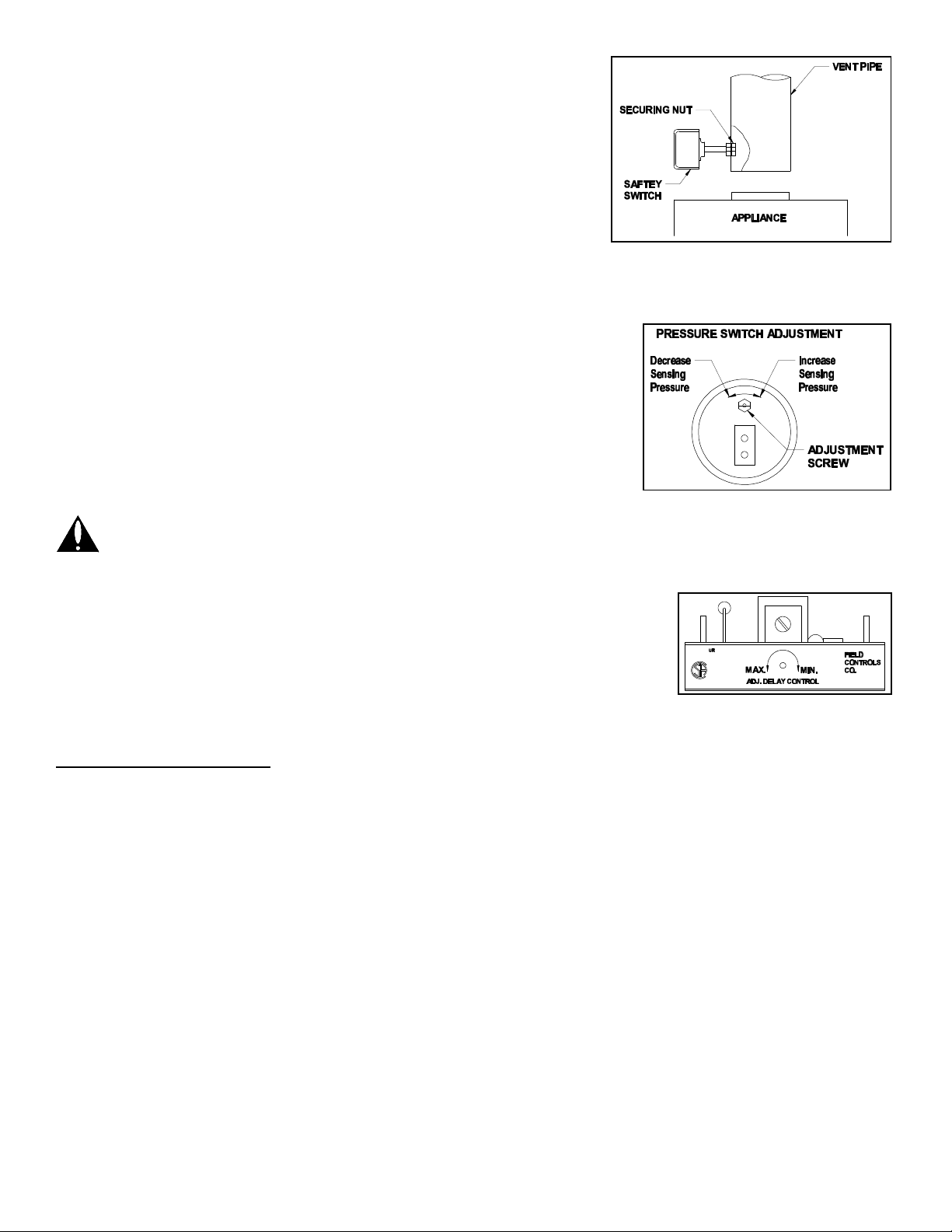
2. Insert the threaded pipe end into the pierced hole, then install
the securing nut, which was removed in Step 1, and tighten
securely (See Fig. 5)
3. Wire safety switch in series into one side of the burner circuit.
Refer to Unit Wiring Instructions.
CAUTION: If for any reason the system has shut down during
operation, the cause of the system failure should be investigated
and corrected before resetting the safety switch and restarting the
system.
Figure 4
Page 2
Page 3
PRESSURE SWITCH SENSING TUBE INSTALLATION:
1. Attach the 1/4 inch tubing connector to the pressure tube on
the SWG Venter. (See Fig. 3)
2. Connect the supplied 1/4" aluminum tubing to the tubing
connector. Route the tubing to the CK-65 junction box and
connect the tubing to the pressure switch. When routing the
tubing, avoid kinking the tubing by bending the tubing too
sharply.
For remote mounted CK-65 Junction Box, use a 1/4" OD copper,
aluminum or plastic tubing and route the tubing to avoid contact
with any heat source.
PROVING SWITCH ADJUSTMENTS:
After proper air flow is established, the pressure switch adjustment is
made by turning the pressure switch adjustment screw clockwise
(See Fig. 6) until burner operation stops. Turn the adjustment screw
counterclockwise until burner ignites. Turn the adjustment screw an
additional 1/4 to 3/4 turn counterclockwise to ensure adequate switch
adjustment.
WARNING: Failure to properly adjust the pressure switch as
specified above could lead to improper operation of the
pressure switch which will result in a hazardous condition and
bodily harm!
Figure 5
Figure 6
POST PURGE TIMING ADJUSTMENT:
To adjust the post purge time, rotate the timer adjustment on the timer
counterclockwise to increase the operation time. To decrease the operation
time, rotate the timer adjustment clockwise. (See Fig. 7) Typical post purge
Figure 7
time should be between 3 to 5 min.
WIRING INSTRUCTIONS
CAUTION: DISCONNECT ELECTRICAL POWER WHEN WIRING POWER VENTER
Wire the venter motor and controls in accordance with the National Electrical Code, manufacturer's
recommendations and/or applicable local codes. UNITS MUST BE GROUNDED. Check ground
circuit to make certain that the unit has been properly grounded. The wiring should be protected by an
over current circuit device rated at 15 amperes. CAUTION must be taken to ensure that the wiring
does not come into contact with any heat source. All line voltage and safety control circuits, between
the venter and the appliance, MUST be wired in accordance with the National Electrical Code for
class one wiring or equivalent methods. Refer to wiring diagrams A and B for typical wiring
installations.
Page 3
Page 4

Wiring Diagram A
Page 4
Wiring Diagram B Typical Wiring With Phelon Control
Page 5

SYSTEM CONTROL CHECK OUT PROCEDURES:
1. Adjust the thermostat to call for heat and observe the power venting system for proper operation
sequence. (Repeat if necessary)
a. Thermostat calls for heat.
b. Relay is energized and venter motor starts.
c. Pressure switch closes and burner starts.
d. Thermostat is satisfied, the burner stops and venter motor should operate for approximately 3
to 5 minutes.
2. While system is operating, disconnect power to the venter motor. This should open the pressure
switch contacts and stop burner operation.
3. Allow vent system to cool. Disconnect the vent pipe between the venter inlet and the appliance
outlet. Block the vent pipe with a noncombustible material. Activate the heating system with the main
burner operating. Allow approximately 2 minutes or less for the secondary safety switch to deactivate
the burner. Reset safety switch and repeat.
TROUBLE SHOOTING HINTS
1. Main burner does not fire when thermostat calls for heat with venter operating.
a. Check pressure switch adjustment
b. Check fuel flow
c. Check wiring connections between pressure switch and burner
d. Check pressure switch for continuity across terminals, during venter operation
2. Venter does not activate when thermostat calls for heat:
a. Jump wire the terminals L1 and M to ensure motor operation
b. Check wiring.
3. Flue gas odor:
a. Check system draft.
b. Check post purge venting time.
c. Check for negative pressure in building.
Page 5
Page 6

DO NOT DESTROY
THESE INSTRUCTIONS MUST REMAIN WITH EQUIPMENT
Installation Information
Model No.: ___________________________________
Installer’s Name: ______________________________
Installer’s Company:____________________________
Phone No.:___________________________________
Date of Installation: ____________________________
Page 6
Page 7

Page 7
Page 8

Page 8
P/N 46294900 Rev A 05/00
 Loading...