

Page 1
SYSTEM CONTROL KIT
Model: CK-62
Designed for use on SWG Series Power Vent Hoods for controlling oil fired heating appliances with 120
VAC controls.
ITEMS INCLUDED IN KIT:
1) Junction box with mounted pressure switch and relay base
1) 120 VAC Relay
1) 2 Ft. Length of 1/4 inch aluminum tubing
1) 1/4 inch tubing connector
1) Flexible conduit connector
1) WMO-1 Secondary Safety Switch
1) PPC-4 Post Purge Switch
DO NOT DESTROY
THESE INSTRUCTIONS MUST REMAIN WITH EQUIPMENT
Page 2

MOUNTING JUNCTION BOX
Figure 3
The junction box can be mounted at the venter or remotely mounted away from the venter. (See Figure 1 & Figure 2)
1. Remove one of the knockouts from the side of the junction box where the pressure switch is mounted. Install the flexible
conduit connector onto the CK-62 Junction Box and secure with fastening nut. If remote mounting the CK-62 Junction
Box, mount the flexible conduit connector onto a 2" x 4" installer supplied junction box.
2. Fasten the flexible conduit from the SWG Venter into the conduit connector. Mount the CK-62 Junction box or installer
supplied junction box onto the wall or floor joist without straining the flexible conduit. Fasten the CK-62 Junction Box
through the four dimpled locations on the base of the box. (See Figure 3)
Figure 1
OIL FIRED SECONDARY SAFETY SWITCH
Installation of a SECONDARY SAFETY SWITCH is recommended for detecting flue gas spillage from a blocked flue system
and/or inadequate draft.
1. Pierce a 5/8" diameter hole into the vent pipe near the appliance outlet. Remove one of the securing nuts from the pipe of
the safety switch. Tighten the other securing nut onto the pipe as far as possible. (See Figure 4)
2. Insert the threaded pipe end into the pierced hole, then install the securing nut, which was removed in Step 1, and tighten
securely. (See Figure 5)
3. Wire safety switch in series into one side of the burner circuit. Refer to Unit Wiring Instructions.
CAUTION: If for any reason the system has shut down during operation, the cause of the system failure should be
investigated and corrected before resetting the safety switch and restarting the system.
Figure 4
Figure 2
Figure 5
Page 2
Page 3

PPC-4 POST PURGE KIT
Figure 7
NOTE: All Oil Fired Appliances must have a post purge kit installed.
Installation of a POST PURGE KIT is REQUIRED for oil fired appliances for the purpose of venting combustion products
after the burner has shut down. This kit has an adjustable thermally activated sensing device that continues to vent the
flue system until the temperature drops below switch opening temperature. (See Chart A)
Pierce a ¼” diameter hole into the vent pipe and mount the POST PURGE SWITCH on the vent pipe between the
barometric draft control and the appliance using the two (2) sheet metal screws. (See Figure 6)
NOTE: Wire the switch normally open. Refer to Unit Wiring Instructions.
POST PURGE TIME ADJUSTMENT PROCEDURE
1. Remove switch cover.
2. Using a screw driver, turn the adjustment screw counterclockwise to increase purge time and clockwise to decrease
purge time. Adjust purge time until no flue gas smell is apparent after venter stops. (See Figure 7)
CHART A
Close on
rise temperature
Open on
fall temperature
Typical post purge time
should be 3 to 5 minutes
150°F to
200°F ± 15°F
95°F to
130°F ± 15°F
Figure 6
Page 3
Page 4

WIRING INSTRUCTIONS
Diagram A
–
Oil Fired System: Single Unit Wiring
Wire the venter motor and controls in accordance with the National Electrical Code, manufacturer's recommendations and/or
applicable local codes. UNIT MUST BE GROUNDED. Check ground circuit to make certain that the unit has been properly
grounded. The wiring should be protected by an over current circuit device rated at 15 amperes. CAUTION must be taken to
ensure that the wiring does not come into contact with any heat source. All line voltage and safety control circuits, between the
venter and the appliance, MUST be wired in accordance with the National Electrical Code for Class I wiring or equivalent
methods.
Route the venter motor and control wiring with an appropriate wiring method. Refer to the Wiring Diagrams A through E.
Page 4
Page 5

Diagram B – Oil Fired System: Wiring with Electronic Primary
Page 5
Page 6

Diagram C –
Typical Wiring for Oil Fired Warm Air Furnace with a Honeywell ST9103 Control Board
Page 6
Page 7

Diagram D – Riello Burner Application
Page 7
Page 8

Diagram E – Multiple Oil Fired Systems
Page 8
Page 9
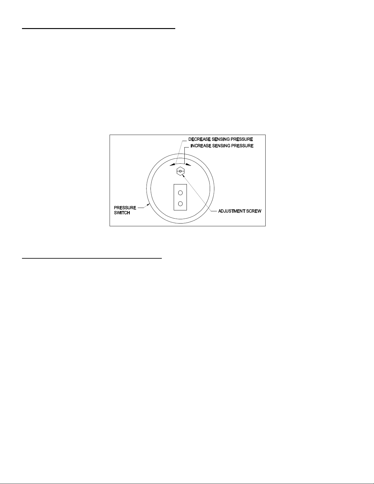
PRESSURE SWITCH SENSING TUBE INSTALLATION
Figure 8
1. Attach the 1/4 inch tubing connector to the pressure tube on the SWG Venter. (See Figure 3)
2. Connect the supplied 1/4" aluminum tubing to the tubing connector. Route the tubing to the CK-62 Junction Box and
connect the tubing to the pressure switch. When routing the tubing avoid kinking the tubing by bending the tubing too
sharply.
For remote mounted CK-62 Junction Box, use a 1/4" OD copper, aluminum or plastic tubing and route the tubing to avoid
contact with any heat source.
Refer to the SWG Venter installation instructions for setting system airflow.
PRESSURE SWITCH ADJUSTMENTS
With the venter air flow set and the appliance operating at the best operating efficiency, adjust the pressure switch by rotating
the adjustment screw clockwise until the burner shuts off, then rotate the adjustment screw counterclockwise until the burner
fires. Rotate the adjustment screw an additional 1/4 turn counterclockwise to ensure proper switch setting. (See Figure 8)
SYSTEM CONTROL CHECK OUT PROCEDURES
1. Adjust the thermostat to call for heat and observe the power venting system for proper operation sequence (Repeat if
necessary).
a. Thermostat calls for heat.
b. Relay is energized and venter motor starts.
c. Pressure switch closes and burner starts.
d. Thermostat is satisfied, burner stops and venter motor should operate for approximately 3 to 5 minutes.
2. While system is operating, disconnect power to the venter motor. This should open the pressure switch contacts and stop
burner operation.
3. (If WMO-1 switch is installed) Allow vent system to cool. Disconnect the vent pipe between the venter inlet and the
appliance outlet. Block the vent pipe with a noncombustible material. Activate the heating system with the main burner
operating. Allow approximately 2 minutes or less for the secondary safety switch to deactivate the burner. Reset safety
switch and repeat.
Page 9
Page 10

10
TROUBLE SHOOTING HINTS
1. Main burner does not fire when thermostat calls for heat with venter operating.
a. Check pressure switch adjustment.
b. Check fuel flow.
c. Check wiring connections between pressure switch and burner.
d. Check pressure switch for continuity across terminals, during venter operation.
2. Venter does not activate when thermostat calls for heat.
a. Jump wire the terminals L1 and M to ensure motor operation.
b. Check wiring.
3. Flue gas odor.
a. Check system draft.
b. Check post purge venting time.
c. Check for negative pressure in building.
MAINTENANCE
1. Motor: Inspect motor once a year; the motor should rotate freely.
2. Wheel: Inspect venter wheel annually, for oil fired heating systems, clear any soot, ash or coating which inhibits either
rotation or air flow. Remove all foreign material before operating.
3. Vent System: Inspect all vent pipe connections annually for looseness and for evidence of flue gas leakage. Seal or
tighten pipe connections if necessary.
Page
Page 11

11
INSTALLATION INFORMATION
MODEL NO.:_____________________________________________________________
CK-62
INSTALLER'S NAME:______________________________________________________
INSTALLER'S COMPANY:__________________________________________________
INSTALLER'S PHONE NO.:_________________________________________________
DATE OF INSTALLATION: _________________________________________________
Page
Page 12

12
P/N 46149200 Rev E 11/05
Page
 Loading...