

Page 1
CONTROL KIT
Model: CK-50
Designed for use with the SWG Series Power Venter for
controlling Natural Gas or L.P. Gas Lochinvar appliances.
ITEMS INCLUDED IN KIT:
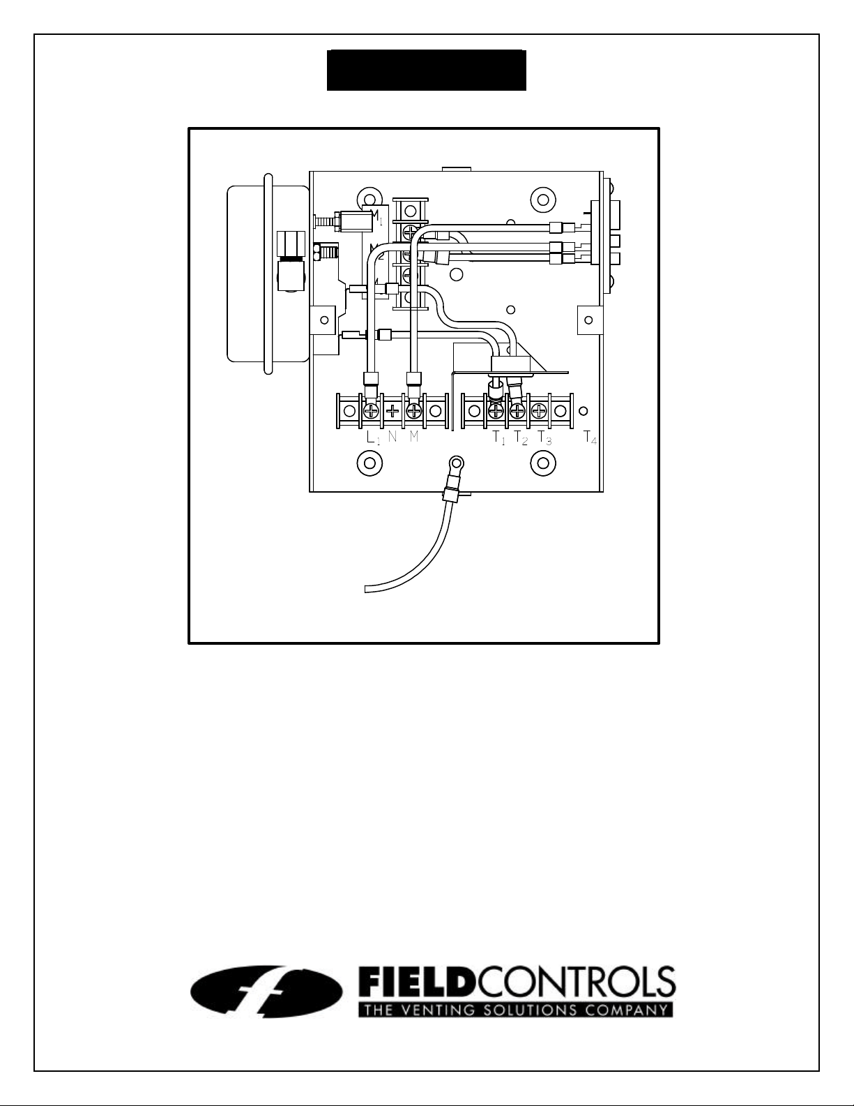
1 - Junction box with mounted pressure switch and relays
1 - Fan control gas pressure switch
1 - 2 ft. length of 1/4 inch aluminum tubing
2 - Flexible conduit connector
1 - 1/4 inch tubing connector
2630 Airport Road • Kinston, NC 28504
Phone: 252-522-3031 • FAX: 252-522-0214
www.fieldcontrols.com
Page 2
INSTALLATION AND ADJUSTMENTS
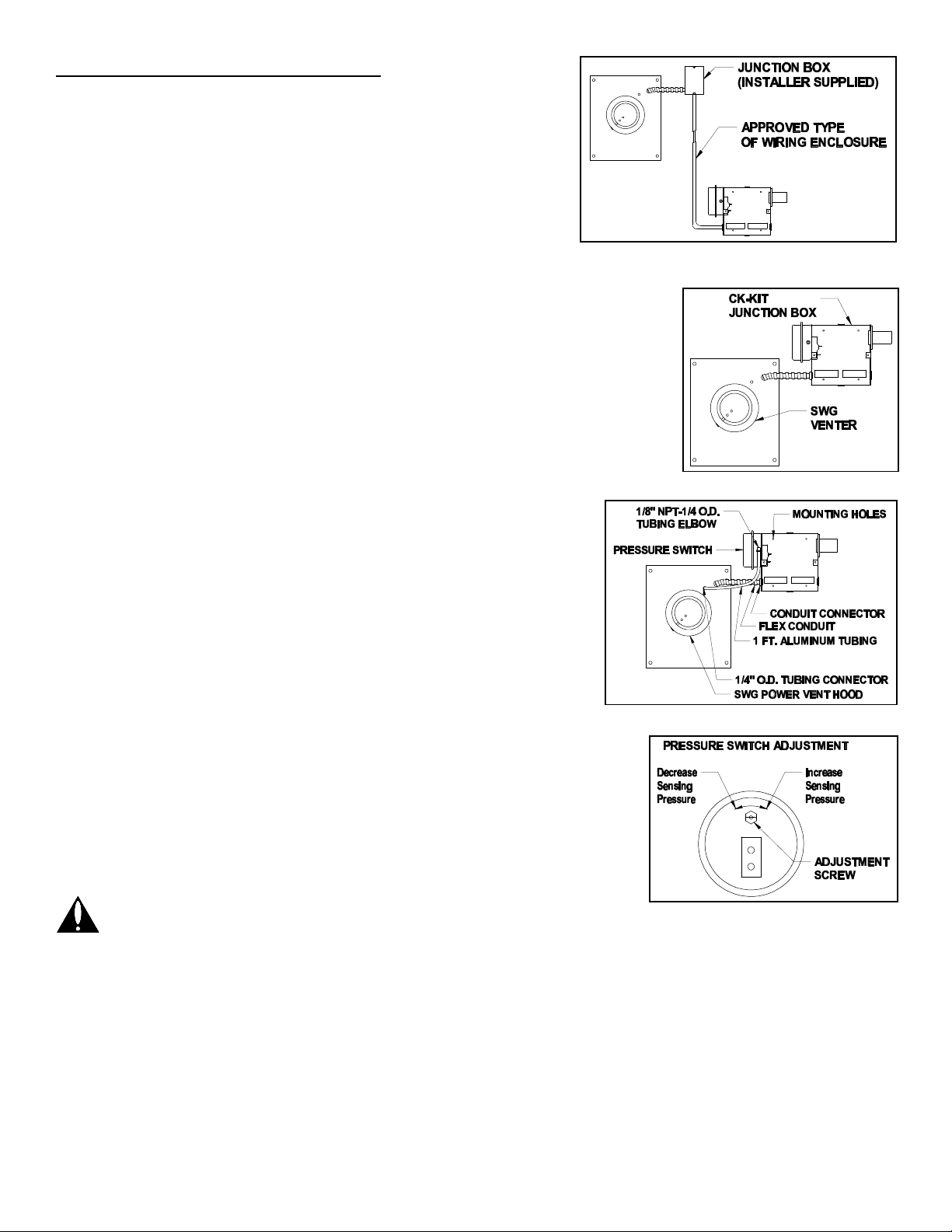
Figure 2
Figure 1
Figure 3
Figure 4
MOUNTING JUNCTION BOX:
The junction box can be mounted at the venter or remotely
mounted away from the venter. (See Fig. 1 & Fig. 2)
1. Remove one of the knockouts from the side of the junction
box where the pressure switch is mounted. Install the
flexible conduit connector onto the CK-50 junction box
and secure with fastening nut. If remote mounting the CK50 junction box, mount the flexible conduit connector onto
a 2" x 4" installer supplied junction box.
2. Fasten the flexible conduit from the SWG Venter into the conduit
connector. Mount the CK-50 junction box or installer supplied junction
box onto the wall or floor joist without straining the flexible conduit.
Fasten the CK-50 junction box through the four dimpled locations on
the base of the box. (See Fig. 3)
PRESSURE SWITCH SENSING TUBE INSTALLATION:
1. Attach the 1/4 inch tubing connector to the pressure tube on
the SWG Venter. (See Fig. 3)
2. Connect the supplied 1/4" aluminum tubing to the tubing
connector. Route the tubing to the CK-50 junction box and
connect the tubing to the pressure switch. When routing the
tubing, avoid kinking the tubing by bending the tubing too
sharply.
For remote mounted CK-50 Junction Box, use a 1/4" OD copper,
aluminum or plastic tubing and route the tubing to avoid contact
with any heat source.
PROVING SWITCH ADJUSTMENTS:
After proper air flow is established, the pressure switch adjustment is
made by turning the pressure switch adjustment screw clockwise
(See Fig. 4) until burner operation stops. Turn the adjustment screw
counterclockwise until burner ignites. Turn the adjustment screw an
additional 1/4 to 3/4 turn counterclockwise to ensure adequate switch
adjustment.
WARNING: Failure to properly adjust the pressure switch as
specified above could lead to improper operation of the
pressure switch which will result in a hazardous condition and
bodily harm!
THERMOSTAT HEAT ANTICIPATOR ADJUSTMENT:
After venting kit installation and checkout, check the amperage current draw through the thermostat
circuit and adjust the thermostat anticipator accordingly.
Page 2
Page 3

WIRING INSTRUCTIONS
CAUTION: DISCONNECT ELECTRICAL POWER WHEN WIRING POWER VENTER
Wire the venter motor and controls in accordance with the National Electrical Code, manufacturer's
recommendations and/or applicable local codes. UNITS MUST BE GROUNDED. Check ground
circuit to make certain that the unit has been properly grounded. The wiring should be protected by an
overcurrent circuit device rated at 15 amperes. CAUTION must be taken to ensure that the wiring
does not come into contact with any heat source. All line voltage and safety control circuits, between
the venter and the appliance, MUST be wired in accordance with the National Electrical Code for
class one wiring or equivalent methods.
The wire connections which must be made on a Sidewall Fan can be divided into two categories;
Power Connections and Control Voltage.
POWER CONNECTIONS
The Power Connections bring 120 volts into the fan control box from a designated power source and
then sends the same 120 volts out to the fan motor.
Step 1 Connect the black, white and green ground wires to a 120 volt designated power
source.
Step2 Connect the black, white and green ground wires to the sidewall fan.
CONTROL VOLTAGE
The Control Voltage brings 120 volts and 24 volts from the boiler to start the fan and make a proving
switch, respectively.
Step 1 Locate an access panel below the gas train on the left side of the boiler.
Remove the access panel and expose the terminal strip and the 2-pin molex plug
(brown and white wires). Connect the black and white wire from the fan control
box to the 2-pin molex plug.
Step 2 Connect the orange and blue wire from the fan control box to the 'B' and 'X' on
the terminal strip. Remove the jumper between the 'B' and 'X'. If there is no
jumper between the 'B' and 'X' and the flow switch has already been installed,
then the orange and blue wire must be tied in series with the flow switch.
Page 3
Page 4

SYSTEM CONTROL CHECK OUT PROCEDURES:
1. Adjust the thermostat to call for heat and observe the power venting system for proper operation
sequence. (Repeat if necessary)
a. Thermostat calls for heat.
b. Relay is energized and venter motor starts.
c. Pressure switch closes and burner starts.
d. Thermostat is satisfied, the burner stops.
2. While system is operating, disconnect power to the venter motor. This should open the pressure
switch contacts and stop burner operation.
TROUBLE SHOOTING HINTS
1. Venter does not activate when thermostat calls for heat:
a. Check wiring.
b. Check gas pressure switch for continuity across terminals when gas valve is pressurized.
c. Check gas pressure.
2. Flue gas odor:
a. Check system draft.
b. Check for negative pressure in building.
DO NOT DESTROY
THESE INSTRUCTIONS MUST REMAIN WITH EQUIPMENT
Model No.:________________________________________
Installer’s Name: ___________________________________
Installer’s Company: ________________________________
Phone No.: _______________________________________
Date of Installation: _________________________________
Installation Information
Page 4
P/N 46382500 05/00
 Loading...