

Page 1
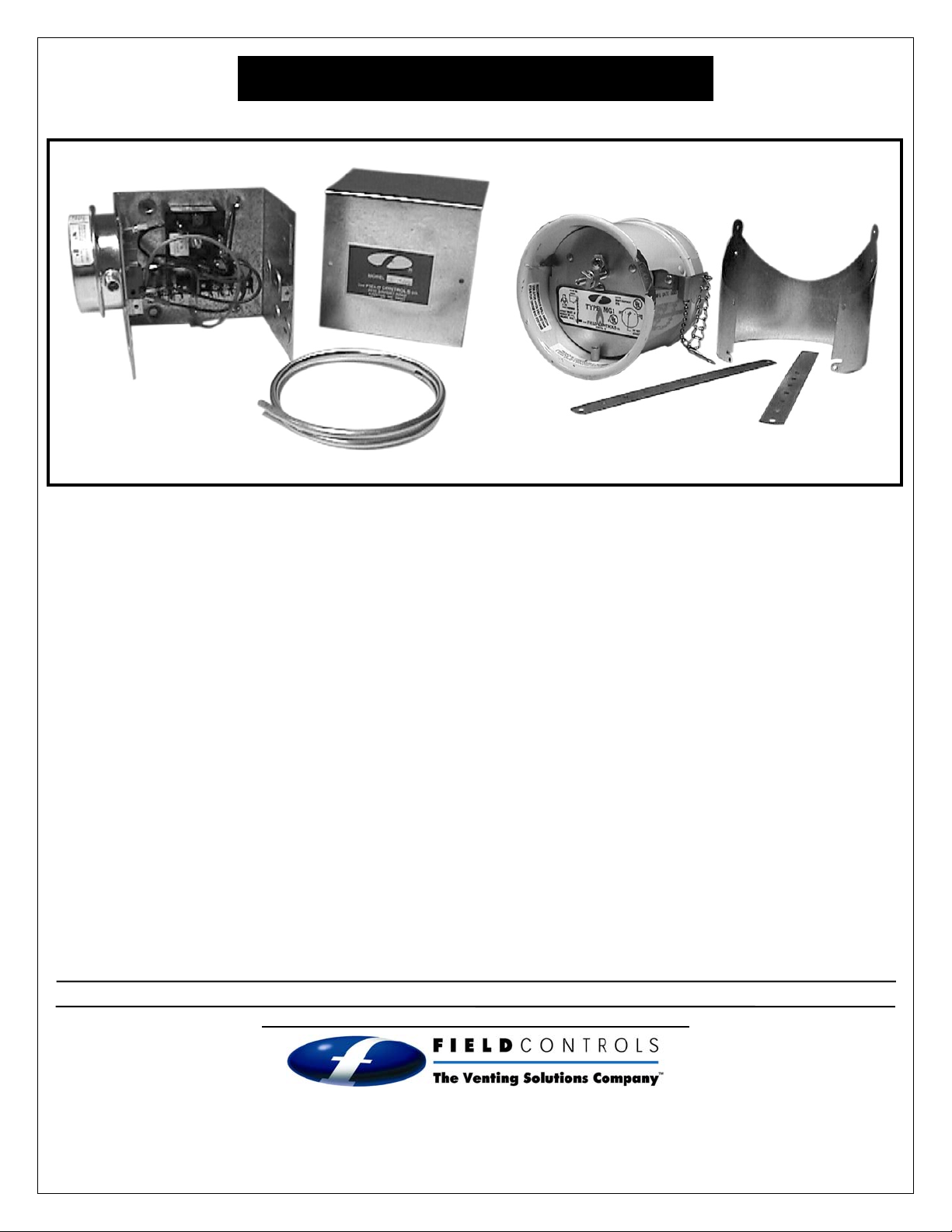
24 VAC SYSTEM CONTROL KIT
Model: CK-43
Tubing
MG1 Barometric
Draft Control
The CK-43 is designed for use with the SWG Series Power
Venter for controlling Natural Gas and L.P. Gas Draft Induced
appliances.
Control kits control the operation of SWG Power Venters. Control
Kits can also control the operation of Field Draft Inducers and
Combustion Air Systems.
I
TEMS INCLUDED IN KIT
1) Junction box with mounted pressure switch and
relay/timer.
1) 1 Ft. Length of 1/4 inch aluminum tubing.
1) 1/4 inch tubing connector
1) Flexible conduit connector
1) 4" MG1 Barometric Draft Control or 5" AF Barometric
Draft Control
This device MUST be installed by a qualified agency in accordance with the manufacturers installation
instructions.
The definition of a qualified agency is: any i ndividual, fir m, corporation or compa ny which eith er in pers on or through a repr esentative is
engaged in, and is responsible for, the installation and operation of gas ap pliances, who is experienced in such work, familiar with all
the precautions required, and has complied with the requirements of the authority having jurisdiction.
DO NOT DESTROY
THESE INSTRUCTIONS MUST REMAIN WITH EQUIPMENT
2630 Airport Road · Kinston, NC 28504
Phone: 252-522-3031· Fax: 252-522-0214
www.fieldcontrols.com
Page 2

INSTALLATION INSTRUCTIONS
M
OUNTING JUNCTION BOX
The junction box can be mounted at the venter or remotely mounted away from
the venter. (See Figure 1 & Figure 2)
1. Remove one of the knockouts from the side of the junction box where the
pressure switch is mounted. Install the flexible conduit connector onto the
CK-43 junction box and secure with fastening nut. If remote mounting the
CK-43 junction box, mount the flexible conduit connector onto a 2" x 4"
installer supplied junction box.
2. Fasten the flexible conduit from the SWG Venter into the conduit
connector. Mount the CK-43 junction box or installer supplied
junction box onto the wall or floor joist without straining the
flexible conduit. Fasten the CK-43 junction box through the four
dimpled locations on the base of the box. (See Figure 3)
P
RESSURE SWITCH SENSING TUBE INSTALLATION
1. Attach the 1/4 inch tubing connector to the pressure tube on the
SWG Venter. (See Figure 3)
Figure 1
2. Connect the supplied 1/4" aluminum tubing to the tubing
connector. Route the tubing to the CK-43 junction box and
connect the tubing to the pressure switch. When routing the
tubing, avoid kinking the tubing by bending the tubing too
sharply.
For remote mounted CK-43 Junction Box, use a 1/4" OD copper,
aluminum or plastic tubing and route the tubing to avoid contact with
any heat source.
Figure 2
Figure 3
Page 2
Page 3
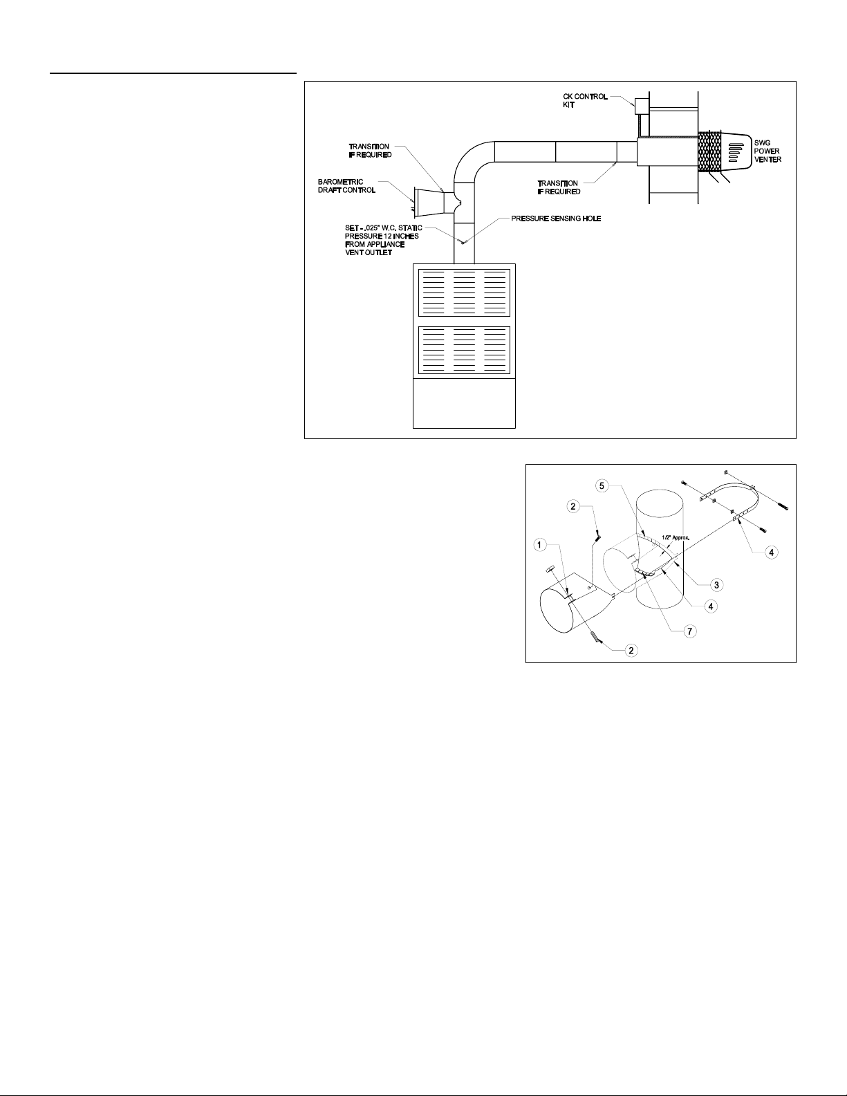
DRAFT CONTROL INSTALLATION
See Figure 4 for typical vent
system layout.
CAUTION: This draft control is
shipped as a single acting draft
control. If the draft control is not
being used on a gas draft induced
furnace, remove the gate stop on
the draft control ring before
installing.
C
OLLAR INSTALLATION
This control is shipped with a collar
patterned to fit a single wall round
vent pipe. To attach this collar to
the flue, see Figure 5 and follow
the instructions below.
1. Bend outward the two ears at
the front corners of the collar.
Bend 90 degrees, 1/4 inch
behind the single hole on the
straps.
Figure 4
2. Insert clamping screw in ears on collar and bolt the remainder of
the collar together.
3. Hold the collar against the side of the flue in the exact position it
is to be installed (shown by dotted lines) and mark the outline
of the collar on the flue.
4. Cut a hole in the flue about 1/2" inside of this outline.
5. Make a series of cuts about 1/2" apart from the edge of this hole
to the outline marks.
Figure 5
6. Strap the collar to the flue pipe.
7. Bend the tabs formed by the series of cuts outward against the inside of the collar to make a tight joint.
8. Refer to Insertion of Draft Control Section.
Page 3
Page 4

DRAFT CONTROL INSTALLATION IN TYPE B VENT PIPE
CAUTION: DO NOT use the supplied collar when mounting draft
control to Type B Vent Pipe. Install by using a Type B Vent Pipe Tee.
1. Install a vent pipe reducer or increaser into the inner pipe and
fasten using sheet metal screws. (See Figures 6 & 7)
2. The opening of the Type B Vent Tee, at the draft control mounting
location, should be sealed with a high temper- ature sealant or
equivalent.
3. Refer to Insertion of Draft Control Section.
I
NSERTION OF DRAFT CONTROL SECTION
Insert the draft control into the collar or tee. The front face of the
control MUST be plumb and the bearing surfaces MUST be level
whether the control is on a horizontal, vertical or sloping flue pipe.
Use a spirit level and level accurately. (See Figures 6 & 7) Secure
the control in the collar by tightening the clamping screws. If a tee is
used or a collar is supplied locally, the control may be held in place
by sheet metal screws.
Figure 6
Figure 7
ADJUSTMENTS
A
DJUSTING THE DRAFT CONTROL WITH 4" MG1
The control MUST be adjusted to the desired draft setting by adding
or removing the washer-type weights supported by the two chains on
the side of the draft control. (See Figure 8) DO NOT move the weight
attached directly to the gate, this is used only for balancing at the
factory.
A
DJUSTING THE DRAFT CONTROL WITH 5" AF
Vertical Flues Mounting - The control is shipped for installation in a
vertical flue. The adjustment weight should be in the right hand slot
when you face the control. See Figure 9.
Horizontal Flues Mounting - For hori-zontal flues, remove the
weight from the right hand slot and attach it to the left hand slot as
shown in Figure 9.
What Draft Setting to Use - When adjusting the control, two things
are essential:
1. The burner must be operating for at least 10 minutes to obtain
maximum chimney draft.
Figure 8
2. An analysis of the flue gases is necessary to determine the
percentage of CO
gas company for the proper CO
and check for presence of CO. Refer to the appliance instructions and/or to the local
2
readings and allowable CO levels. A rule of thumb for draft setting is
2
Figure 9
between .01" to .03" of water column draft at the appliance outlet. (Check equipment requirement.)
Changes in the adjustment of the 4" MG1 control should be made by adding or removing the washer-like
weights (supplied with the control) to or from the weight holder chain assembly. After the control is adjusted,
it's action will be entirely automatic, the gate will open or close by itself to correct for changes in the draft that
occur in the chimney.
Page 4
Page 5

PROVING SWITCH ADJUSTMENTS
After proper air flow is established, the pressure switch adjustment is made
by turning pressure switch adjustment screw clockwise (See Figure 10)
until burner operation stops. Turn the adjustment screw counter clockwise
until burner ignites. Turn the adjustment screw an additional 1/4 to 3/4 turn
counterclockwise to ensure adequate switch adjustment.
WARNING: Failure to properly adjust the pressure switch as
specified above could lead to improper operation of the pressure
switch which will result in a hazardous condition and bodily harm!
THERMOSTAT HEAT ANTICIPATOR ADJUSTMENT
After venting kit installation and checkout, check the amperage current
draw through the thermostat circuit and adjust the thermostat anticipator
accordingly.
POST PURGE TIMER ADJUSTMENT
To adjust the post purge time, refer to Figures 11 & 12.
For timer that looks like Figure 11: Rotate the timer adjustment on the
timer clockwise to increase the operation time. To decrease the operation
time, rotate the timer adjustment counterclockwise.
For timer that looks like Figure 12: Rotate the timer adjustment on the
timer counterclockwise to increase the operation time. To decrease the
operation time, rotate the timer adjustment clockwise.
*Typical post purge time should be between 3 to 5 min.
WIRING
CAUTION: Disconnect electrical power
when wiring power venter.
Figure 10
Figure 11
Figure 12
NOTE: If using this control kit with an
electronic thermostat you need an
RJR-5 isolation relay. Wire the venter
motor and controls in accordance with
the National Electrical Code,
manufacturer's recommendations
and/or applicable local codes. UNITS
MUST BE GROUNDED. Check ground
circuit to make certain that the unit has
been properly grounded. The wiring
should be protected by an over current
circuit device rated at 15 amperes.
CAUTION must be taken to insure that
the wiring does not come into contact
with any heat source. All line voltage
Diagram A
and safety control circuits, between the
venter and the appliance, MUST be wired in accordance with the National Electrical Code for class one wiring
or equivalent methods. Route the venter motor and control wiring with an appropriate wiring method. Refer to
the Wiring Diagram A.
Page 5
Page 6

SYSTEM CONTROL CHECK OUT PROCEDURES
1. Adjust the thermostat to call for heat and observe the power venting system for proper operation sequence
(Repeat if necessary).
a. Thermostat calls for heat.
b. Relay is energized and venter motor starts.
c. Pressure switch closes and burner starts.
d. Thermostat is satisfied, the burner stops.
e. This starts the post purge cycle.
2. While system is operating disconnect power to the venter motor. This should open the pressure switch
contacts and stop burner operation.
TROUBLE SHOOTING HINTS
1. Main burner does not fire when thermostat calls for heat with venter operating.
a. Check pressure switch adjustment.
b. Check wiring connections between pressure switch and burner. c. Check pressure switch for conti-nuity
across terminals, during venter operation.
2. Venter does not activate when thermostat calls for heat.
a. Check wiring.
b. Check relay for proper operation.
3. Flue gas odor.
a. Check system draft.
b. Check for negative pressure in building.
c. Check post purge time.
MAINTENANCE
1. Motor: Inspect motor once a year, the motor should rotate freely.
2. Wheel: Inspect venter wheel annually to clear a ny soot, ash or coating which inhibits either rotation or air
flow. Remove all foreign material before operating.
3. Vent System: Inspect all vent pipe connections annually for looseness and for evidence of flue gas
leakage. Seal or tighten pipe connections if necessary.
Page 6
Page 7

INSTALLATION INFORMATION
MODEL NO.:____________________________________________________________
CK-43 Control Kit
INSTALLER’S NAME:_____________________________________________________
INSTALLER’S COMPANY:_________________________________________________
INSTALLER’S PHONE NO.:________________________________________________
DATE OF INSTALLATION:_________________________________________________
Page 7
Page 8

Page 8
P/N 46190700 Rev D 11/07
 Loading...