

Page 1
SYSTEM CONTROL KIT
Model: CK-41F
ITEMS INCLUDED IN KIT:
) Junction box with mounted pressure
switch and post purge timer
) Fan control gas pressure switch
) 2 ft. length of 1/4 inch aluminum tubing
) Flexible conduit connector
) GSK-3 Spillage switch
) 1/4 inch tubing connector
Designed for use with the SWG Series Power Venter for controlling Natural
Gas or L.P. Gas appliances.
This device MUST be installed by a qualified agency in accordance with the manufacturers installation
instructions.
The definition of a qualified agency is: any individual, firm, corporation or company which either in person or through a
representative is engaged in, and is responsible for, the installation and operation of gas appliances, who is experienced
in such work, familiar with all the precautions required, and has complied with the requirements of the authority having
jurisdiction.
DO NOT DESTROY
THESE INSTRUCTIONS MUST REMAIN WITH EQUIPMENT
2630 Airport Road · Kinston, NC 28504
Phone: 252-522-3031· Fax: 252-522-0214
www.fieldcontrols.com
Page 2
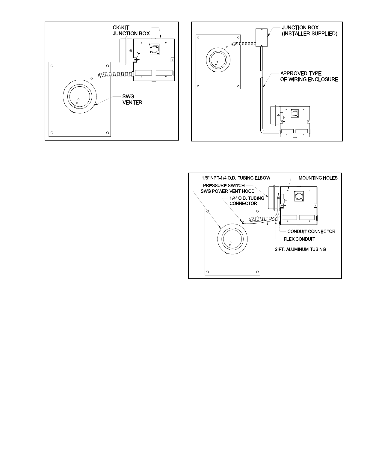
Figure 1
Figure 2
M
OUNTING JUNCTION BOX
The junction box can be mounted at the venter or
remotely mounted away from the venter. (See Figure 1 &
Figure 2)
NOTE: Make sure pressure switch is in a vertical
position. The pressure switch will not sense properly in a
horizontal position.
1. Remove one of the knockouts from the side of the
junction box where the pressure switch is mounted.
Install the flexible conduit connector onto the CK-41F
junction box and secure with fastening nut. If remote
mounting the CK-41F junction box, mount the flexible
conduit connector onto a 2" x 4" installer supplied
junction box.
2. Fasten the flexible conduit from the SWG Venter into
the conduit connector. Mount the CK-41F junction box
Figure 3
or installer supplied junction box onto the wall or floor
joist without straining the flexible conduit. Fasten the
CK-41F junction box through the four dimpled
locations on the base of the box. (See Fig. 3)
P
RESSURE SWITCH SENSING TUBE INSTALLATION
1. Attach the 1/4 inch tubing connector to the pressure tube on the SWG Venter. (See Figure 3)
2. Connect the supplied 1/4" aluminum tubing to the tubing connector. Route the tubing to the CK-41F junction box and
connect the tubing to the pressure switch. When routing the tubing, avoid kinking the tubing by bending the tubing too
sharply.
For remote mounted CK-41F Junction Box, use a 1/4" OD copper, aluminum or plastic tubing and route the tubing to
avoid contact with any heat source. A maximum of 80 feet of ¼” tubing can be used with the SWG Series power venter.
Page 2
Page 3
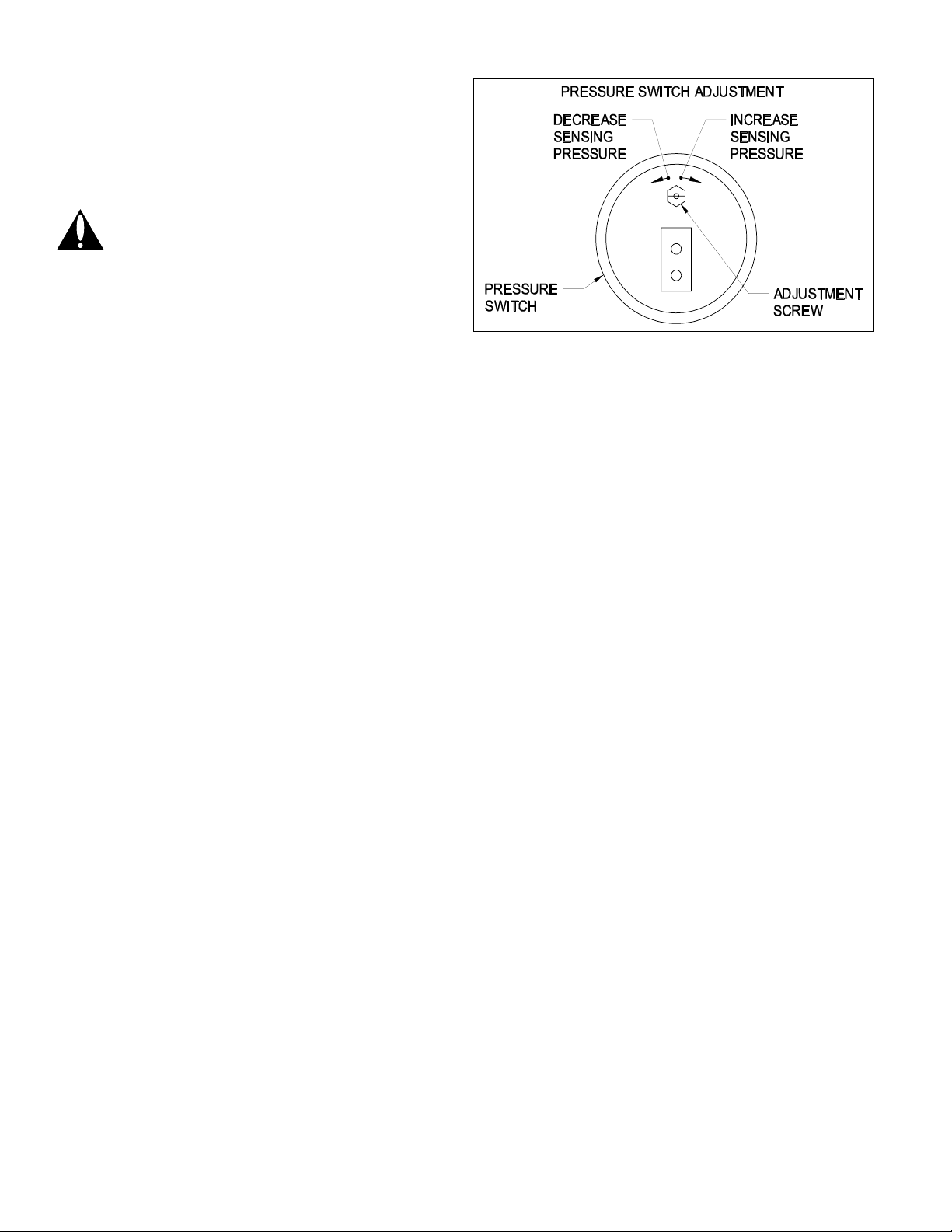
PROVING SWITCH ADJUSTMENTS
After proper air flow is established, the pressure switch
adjustment is made by turning the pressure switch
adjustment screw clockwise (See Figure 4) until burner
operation stops. Turn the adjustment screw counter
clockwise until burner ignites. Turn the adjustment
screw an additional ¼ to ¾ turn counterclockwise to
ensure adequate switch adjustment.
WARNING: Failure to properly adjust the
pressure switch as specified above could lead
to improper operation of the pressure switch,
which will result in a hazardous condition and
bodily harm!
T
HERMOSTAT HEAT ANTICIPATOR ADJUSTMENT
After venting kit installation and checkout, check the
Figure 4
amperage current draw through the thermostat circuit
and adjust the thermostat anticipator accordingly.
W
IRING INSTRUCTIONS
CAUTION: DISCONNECT ELECTRICAL POWER WHEN WIRING POWER VENTER,
Wire the venter motor and controls in accordance with the National Electrical Code, manufacturer's recommendations
and/or applicable local codes. UNITS MUST BE GROUNDED. Check ground circuit to make certain that the unit has been
properly grounded. The wiring should be protected by an over-current circuit device rated at 15 amperes. CAUTION must
be taken to ensure that the wiring does not come into contact with any heat source. All line voltage and safety control
circuits, between the venter and the appliance, MUST be wired in accordance with the National Electrical Code for class
one wiring or equivalent methods. Route the venter motor and control wiring with an appropriate wiring method. Refer to
Wiring Diagrams.
L
OW VOLTAGE WIRING INSTRUCTIONS FOR BOILERS AND WARM AIR FURNACES
1. With boilers, locate terminal on spark ignition module or gas valve, (if standing pilot) which would normally be 24 volts
hot on a call for heat. With spark ignition systems, this terminal could be TH-W or 24 V depending on the spark
ignition control.
2. With warm air furnaces, locate terminal W in furnace junction box.
3. Remove wire from this terminal and reroute to T1 on CK-41F.
4. With boilers, connect T3 on CK-41F to hot side of gas valve (if standing pilot) or to terminal TH-W or 24 V, if spark
ignition.
NOTE: Remember, the correct terminal is the one that would normally be hot on a call for heat.
5. With warm air furnaces, connect T3 on CK-41F to terminal W in furnace junction box.
6. Connect T2 on CK-41F to a 24 volt neutral on transformer or where convenient, or to the C terminal in the furnace fan
center.
L
INE VOLTAGE WIRING INSTRUCTIONS
1. Connect 120 volts hot power source wire to terminal L1 on CK-41F.
2. Connect 120 volts neutral power source wire and white wire from venter motor to terminal N on the CK-41F.
3. Connect black wire from venter motor to terminal M on the CK-41F.
R
EFER TO THE SWG VENTER INSTALLATION INSTRUCTIONS FOR SETTING SYSTEM AIRFLOW.
Page 3
Page 4

Diagram A – Typical Furnace Wiring
Diagram B – Boiler Wiring with Aquastat
Page 4
Page 5

Page 5
Page 6

Diagram E
Page 6
Page 7

SYSTEM CONTROL CHECK OUT PROCEDURES
1. For furnaces or boilers, adjust the thermostat to call for heat and observe the power venting system for proper
operation sequence. (Repeat if necessary)
a. Thermostat calls for heat.
b. Relay is energized and venter motor starts.
c. Pressure switch closes and burner starts.
d. Thermostat is satisfied, the burner stops.
e. This starts the post purge cycle. Purge time 1 to 2 min.
2. While system is operating, disconnect power to the venter motor. This should open the pressure switch contacts and
stop burner operation.
TROUBLE SHOOTING HINTS
1. Venter does not activate when thermostat calls for heat.
a. Check wiring.
b. Check for 24 volts between T1 and T2 on the CK-41F control kit.
c. If there is 24 volts replace post purge timer.
2. Flue gas odor.
a. Check system draft.
b. Check for negative pressure in building.
REPAIR AND REPLACEMENT PARTS
REPAIR AND REPLACEMENT PARTS LIST
DESCRIPTION PART NUMBER
Pressure Switch 46083000
Post Purge Timer 46282800
Page 7
Page 8

INSTALLATION INFORMATION
MODEL NO.:____________________________________________________________
CK-41F
INSTALLER'S NAME:_____________________________________________________
INSTALLER'S COMPANY:_________________________________________________
INSTALLER'S PHONE NO.:________________________________________________
DATE OF INSTALLATION:_________________________________________________
Page 8
P/N 46335000 Rev A 10/06
 Loading...