

Page 1

WATER HEATER CONTROL KIT
Model: CK-21
Designed for use on SWG Series Power Venters for controlling Natural Gas
and L.P. Gas Instantaneous Water Heaters with a pressure tap port.
ITEMS INCLUDED IN KIT:
1) Junction box
1) Fan control gas pressure switch
1) 1 Ft. Length of 1/4 inch aluminum tubing
1) 1/8" NPT x 3 inch pipe nipple
1) 1/8" NPT x 1/4 inch OD tubing elbow
1) 1/8" NPT pipe tee
1) 6 Foot length of 12-2 wire
1) 8 Inch jumper wire
1) Flexible conduit connector
2) Spillage Switches
3) Adhesive Tabs
DO NOT DESTROY
THESE INSTRUCTIONS MUST REMAIN WITH EQUIPMENT
Page 2
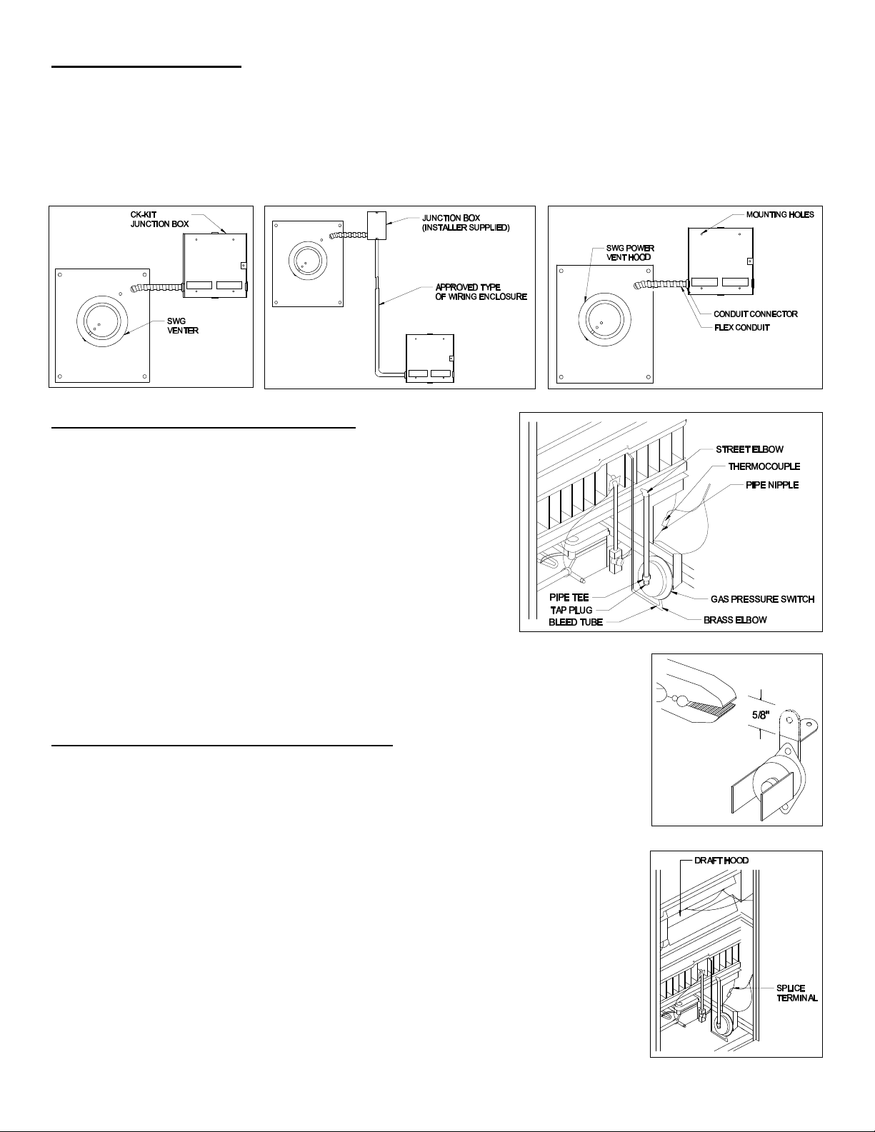
MOUNTING JUNCTION BOX
Figure 1
Figure 2
The junction box can be mounted at the venter or remotely mounted away from the venter. (See Figure 1 & Figure 2)
1. Remove one of the knockouts from the side of the junction box where the pressure switch is mounted. Install the
flexible conduit connector onto the CK-21 junction box and secure with fastening nut. If remote mounting the CK-21
junction box, mount the flexible conduit connector onto a 2" x 4" installer supplied junction box.
2. Fasten the flexible conduit from the SWG Venter into the conduit connector. Mount the CK-21 junction box or installer
supplied junction box onto the wall or floor joist without straining the flexible conduit. Fasten the CK-21 junction box
through the four dimpled locations on the base of the box. (See Figure 3)
Figure 3
INSTALLATION OF GAS PRESSURE SWITCH
CAUTION: Maximum gas pressure MUST NOT exceed 14" W.C.
Pressure. Gas supply must be shut off before working on piping
systems.
NOTE: Seal all pipe connections with pipe thread sealant.
1. Remove pressure tap plug in manifold.
2. Install 1/8" NPT Street elbow (if required for mounting the gas
pressure switch vertically) in place of the pressure tap plug. Then
install the 3" x 1/8" NPT nipple, pipe tee and pressure tap plug.
(See Figure 4)
3. Install the Gas Pressure Switch into the side of the pipe tee.
Position the switch vent, on the side of the switch, down. Next,
install the brass elbow into the switch vent on the Pressure Switch.
4. Install the bleed tube into the brass elbow; then route the tubing
up and terminate it near burner. (See Figure 4)
NOTE: Gas Pressure Switch MUST be mounted vertically.
CAUTION: Bleed tube MUST be installed with its termination near the main burner.
INSTALLATION OF SAFETY SPILLAGE SWITCHES
NOTE: Water Heater MUST have safety switches installed. Installation of a SAFETY
SWITCH is REQUIRED for water heaters, for the purpose of detecting spillage from a
blocked flue system and/or inadequate draft.
1. Bend the tab attached to the spillage switches as shown in Figure 5.
2. Mount the spillage switches along the opening of the draft hood. (See Figure 6)
Connect one terminal on each spillage switch with the 8" jumper wire. Then connect
the other two terminals to the jacketed wire. Route the jacketed wire along the frame or
enclosure of the water heater, keeping the wires away from any HOT surface area.
Secure the wire with adhesive tabs. (See Figure 6)
3. Splice the jacketed wire in series with one of the leads connected to the thermocouple
splicing terminal. (See Figure 6)
CAUTION: If for any reason the system has shut down during operation, the cause of the
system failure should be investigated and corrected before resetting the safety switch and
re-starting the system.
Figure 4
Figure 5
Figure 6
Page 2
Page 3

WIRING
Diagram A
Wire the venter motor and controls in accordance with the National Electrical Code, manufacturer's recommendations
and/or applicable local codes. UNIT MUST BE GROUNDED. Check ground circuit to make certain that the unit has been
properly grounded. The wiring should be protected by an over current device rated at 15 amperes. CAUTION must be
taken to ensure that the wiring does not come into contact with any heat source. All line voltage and safety control circuits
between the venter and the appliance must be wired in accordance with the National Electrical Code for Class I wiring or
equivalent methods.
Route the venter motor and control wiring with an appropriate wiring method. Refer to Wiring Diagram A.
Refer to SWG Venter Installation Instructions for setting system airflow.
Page 3
Page 4

SYSTEM CHECK-OUT PROCEDURE FOR HOT WATER HEATER CONTROLS
P/N 46159000 Rev A 02/01
WATER HEATER GAS PRESSURE SWITCH
1. Following water heater manufacturer's instructions to light the pilot, turn the gas control valve to the ON position.
2. Open the hot water faucet; this should energize the venter. Next, close the hot water faucet; this should de-energize
the venter.
3. Repeat Step 2 to assure proper operation.
SAFETY SPILLAGE SWITCHES
1. Allow water heater to heat up to operating temperature by opening the hot water faucet, then disconnect the power
supply to the venter.
2. Allow approximately 2 minutes for the spillage switches to sense the spillage of flue gas and de-energize the
thermocouple circuit. This will halt the gas flow to the pilot and burner.
3. Wait 2 or 3 minutes, reset spillage switches and relight pilot. Then perform a second spillage test (Steps 1 and 2).
TROUBLE SHOOTING HINTS
1. Venter does not activate when hot water faucet is opened.
a. Check wiring.
b. Check gas pressure switch for continuity across terminals when gas valve is pressurized.
c. Check gas pressure.
d. Check amount of water flow.
2. Flue gas odor.
a. Check system draft.
b. Check for negative pressure in building.
3. Pilot will not stay lit.
a. Solder all spillage switch wire terminal connections.
b. Check reset buttons on spillage switches.
MAINTENANCE
1. Motor: Inspect motor once a year, the motor should rotate freely.
2. Wheel: Inspect venter wheel annually to clear any soot, ash or coating which inhibits either rotation or air flow.
Remove all foreign material before operating.
3. Vent System: Inspect all vent pipe connections annually for looseness and for evidence of flue gas leakage. Seal or
tighten pipe connections if necessary.
INSTALLATION INFORMATION
MODEL NO.:_____________________________________________________________
INSTALLER'S NAME:______________________________________________________
INSTALLER'S COMPANY:__________________________________________________
INSTALLER'S PHONE NO.:_________________________________________________
DATE OF INSTALLATION: _________________________________________________
CK-21
Page 4
 Loading...