

Page 1
COMBUSTION AIR SYSTEM
Model: CAS-2WM
WEIL-MCLAIN OUTSIDE AIR KIT
FOR USE WITH OIL BURNER MODELS QB-180 & QB-300
4” VRV
AIR BOOT™
4” IAH HOOD
The Air Boot™ model CAS-2WM is for use only on the designated burner(s) as
described in these instructions only when the specific burner includes this Air Boot™
when shipped from the burner manufacturer or where the burner instructions
specifically reference the model CAS-2WM Air Boot™ as an optional air intake
system.
ITEMS INCLUDED IN KIT: INSTALLER SUPPLIED ITEMS:
1 - Air Boot™ Air Duct Pipe and Elbows as needed
1 - 4” VRV (Vacuum Relief Valve) -use 4” Dryer Venter, Aluminum or
1 - 4” IAH Hood Galvanized Steel
1 - Set of Gaskets ¼” NPT 90° street ell for oil line if needed
1 - Burner Coupling Set Exterior rated caulk, silicone sealant or
2 - Mounting Bolts equivalent
Page 2
THE PURPOSE OF THE VACUUM RELIEF VALVE (VRV)
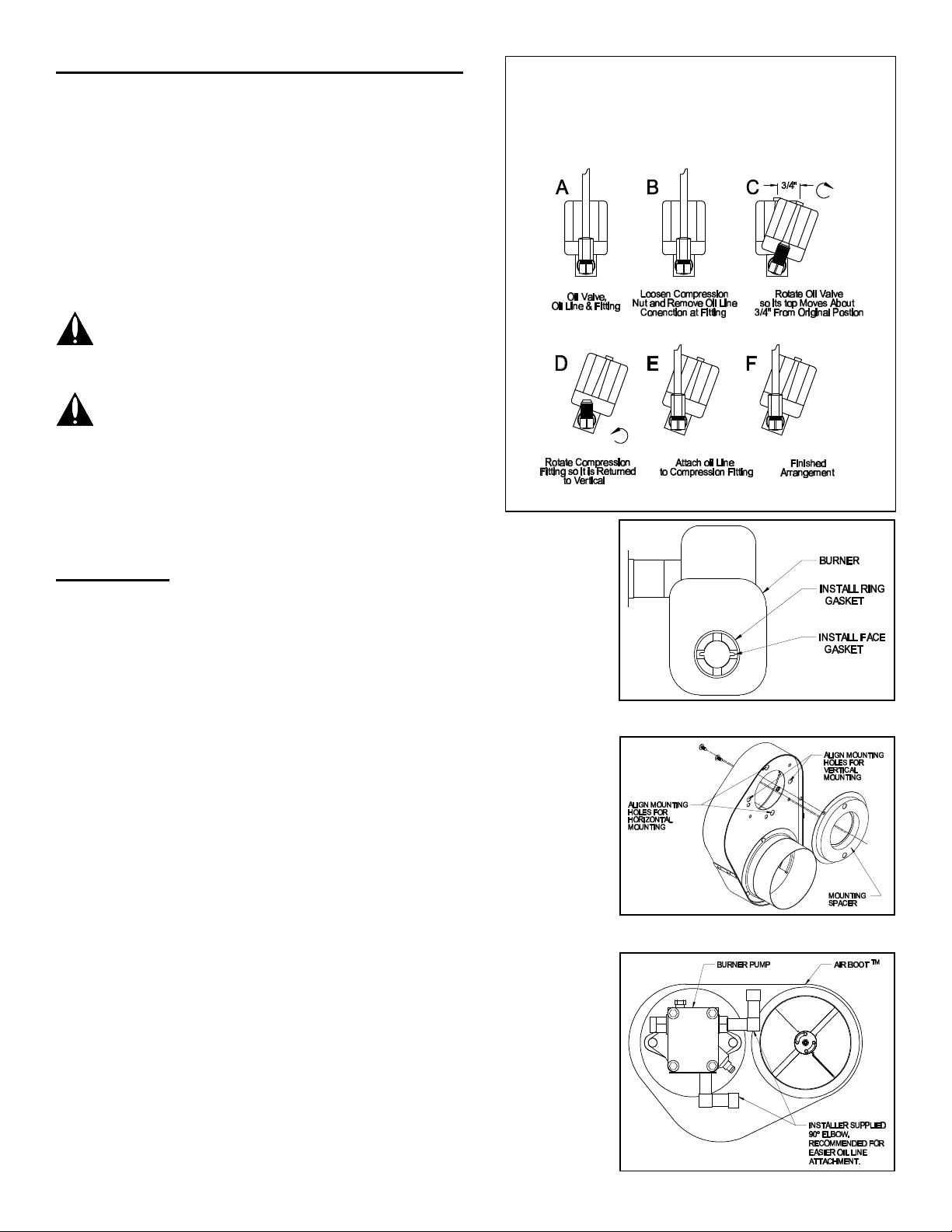
Figure 1
Rotate Oil Solenoid valve and realign 90° fitting as
shown below. Do not reconnect the oil line as in E
The vacuum relief valve provides combustion air to the burner
if the outside air supply is interrupted for any reason. Typical
situations would be blockage of the air intake or duct, or wind
effect which cause a negative pressure at the air intake hood.
VRV OPERATION
With normal air flow through the air intake hood and duct, the
VRV stays closed. All combustion air comes in through the air
duct. If the pressure in the Air Boot™ drops, the valve door
opens. Room air flows in through the VRV to provide the air
needed for combustion. When the Air Boot™ pressure returns
to normal, the VRV closes.
WARNING: This symbol is used in these instructions
to indicate presence of hazards, which can cause
severe personal injury, death or substantial property
damage.
WARNING: Failure to perform the following can cause
severe personal injury, death or substantial property
damage:
• Read all instructions before starting
• Follow all instructions in proper order
• Turn off service switch on boiler and any other
electrical disconnect switches
• Turn off the fuel supply valve(s) and disconnect fuel lines from the
burner
and F until you have installed the Air Boot™
INSTALLATION
1. Rotate the burner oil solenoid valve as shown in Figure 1, steps A-D. Do
not reconnect the oil line (per E-F). The solenoid valve must be aligned as
shown to prevent interference with the Air Boot™.
2. Remove the two ¼” bolts holding the oil pump to the burner housing.
Remove the oil pump.
3. Remove the screw which holds the air band to the housing. Remove the
air band.
4. Install the sealing gaskets onto the burner housing (See Figure 2).
5. Install mounting spacer onto Air Boot™ (See Figure 3).
6. Place the Air Boot™ on the housing, through the large opening in the back
side of the Air Boot™ (See Figure 3). Press the Air Boot™ into position
and align roughly plumb with the burner. Align the Air Boot™ mounting
holes with the burner oil pump mounting holes.
NOTE: Replace pump coupling with the coupling supplied with kit.
7. Now put the oil pump and the AirBoot™ kit coupling back into place.
Replace the two ¼” oil pump mounting screws. Tighten the screws.
8. Reconnect the burner oil line to the ell fitting on the oil pump per Figure 1,
drawings E and F.
Figure 2
Figure 3
Page 2
Figure 4
Page 3

9. Mount the VRV tee assembly or 90° elbow onto the Air Boot™ intake.
Fasten using three (3) sheet metal screws on all joints (See Figure 5).
10. Assemble the VRV balance weight onto the gate. Screw the weight all the
way in. Then attach lock nut and knurl nut (See Figure 6).
11. Mount the VRV assembly onto the tee and fasten with the supplied screw
and nut in collar tabs. To ensure proper operation, Check the gate for
being level across the pivot points and plumb (See Figure 7).
12. Refer to Figure 8 for general installation layout.
AIR DUCT AND AIR INTAKE HOOD (See Figure 8)
1. Mount the air intake hood through an outside wall. It must be at least 12”
(inches) ABOVE grade or snow line.
2. Locate the air intake hood at least 3’ (feet) BELOW (or 6 feet horizontally
from) any appliance VENT termination.
3. When the appliance is sidewall vented, locate the air intake hood on the
same side of the building as the appliance vent outlet.
4. Always mount the air hood with the intake pointed down.
5. To install the air intake hood, cut a 4 ¼” hole through the side of the
building. Slide the hood through the wall and fasten with appropriate
screws.
6. Seal around the exterior plate with an exterior rated caulk, silicone sealant
or equivalent.
7. Locate the air hood so the air piping length doesn’t exceed the limits
below:
Number of Elbows
Maximum Length
of Air Pipe
2 to 4 35 Feet
5 28 Feet
6 21 Feet
7 14 Feet
Figure 5
Figure 6
8. Construct the air duct piping with 4” diameter dryer vent or aluminum or
galvanized steel pipe, using as few elbows as possible.
9. Fasten and support the air duct piping to prevent damage and separation
of joints.
Figure 7
Figure 8
Page 3
Page 4

ADJUSTMENTS
P/N 46330800 Rev D 11/00
AIR INTAKE BOOT AIR SETTING
1. Follow the instructions in the Boiler and Burner Installation Manuals for adjusting and setting the burner.
WARNING: Failure to properly adjust the burner after installing this kit can result in severe personal injury, death or
substantial property damage.
2. Loosen the air band screw on the Air Boot™. Position the screw at the initial setting on the following page. Use this
setting only as a starting point. Do not leave the burner with this setting unless your testing proves it to be acceptable.
INITIAL AIR BOOT™ AIR CONTROL SETTINGS
Input Range (GPH) Air Band Setting
0.55 – 0.70 25°
0.75 - 1.00 60°
1.10 - 1.75 80°
2.00 - 2.55 180°
3. Start the burner and adjust the air control as needed to achieve the required CO2 and smoke levels. Set over fire
draft to appliance manufacturers’ specifications (typically -.02” of water). Secure air control knob with indicator
bracket. If draft levels are not obtainable or controllable, use standard industry methods to control the draft or call the
Field Controls Tech Line at 1-800-742-8368 for more information.
4. Adjust the counterweight on the vacuum relief valve so the gate remains closed during the burner setup and testing.
VACUUM RELIEF VALVE COUNTERWEIGHT
1. After you have completed adjusting the burner, adjust the VRV counterweight.
2. With the burner running normally, rotate the counterweight screw counterclockwise until the gate just begins to open.
3. Check the combustion again to verify no changes have occurred. If OK, hold the counterweight screw in position and
tighten the hex nut against the gate to lock the screw permanently in position.
Page 4
 Loading...