

Page 1
COMBUSTION AIR SYSTEM
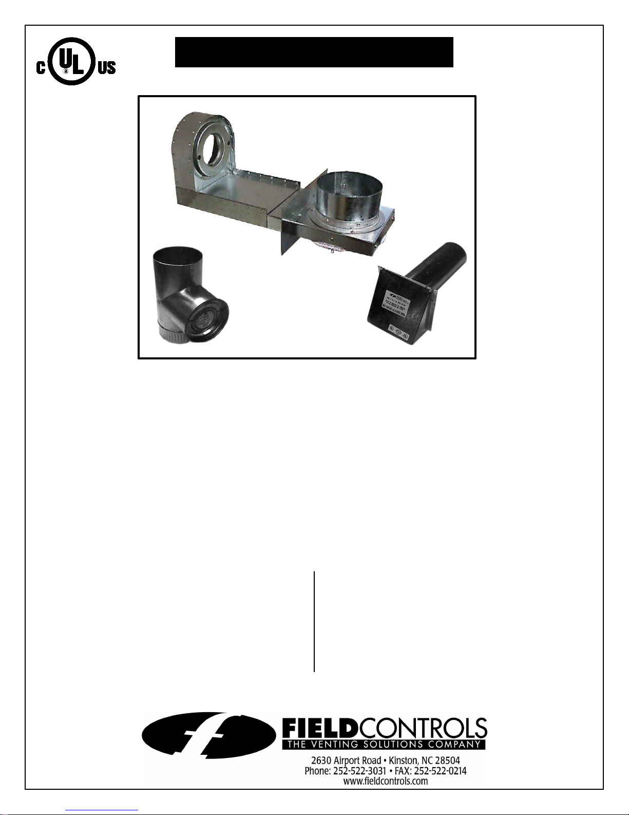
Model: CAS-2B-90E Furnace Boot™
FURNACE
BOOT™
4” VRV
4” IAH
HOOD
This product is designed for use on the Beckett AFG burners,
for the purpose of routing combustion air directly to the
burner, with the added safety feature of the vacuum relief
valve.
NOTE: For burner inputs up to 1.5 gph at 100 psi input
pressure or equivalent.
“The Furnace Boot™ model CAS-2B-90E is for use only on
the designated burner(s) as described in these instructions
only when the specific burner includes this Furnace Boot™
when shipped from the burner manufacturer or where the
burner instructions specifically reference the model CAS-2B90E Furnace Boot™ as an optional air intake system.”
ITEMS INCLUDED IN KIT:
1 - 90E Furnace Boot™
1 - Set of Gaskets
1 - 4” VRV
1 - 4” IAH Hood
1 - Burner Coupling Set
INSTALLER SUPPLIED ITEMS:
Duct Piping and Elbows
90° Elbows;
¼ “ NPT Female x ¼” NPT Male for
routing oil line
2 - Mounting Bolts
Page 2

THE PURPOSE OF THE VACUUM
RELIEF VALVE (VRV)
The Vacuum Relief Valve is a safety
device to guard against combustion
problems associated with directly
connecting oil burners to the outside.
Typical problems can be caused by
blockage of the intake termination, icing
up of the ductwork and effects of leeward
side wind effects on a building.
VRV OPERATION
The VRV gate operates on changes in the
vacuum pressure generated by the inlet to
the oil burner. The VRV gate will remain
closed during normal burner operation.
During an abnormal operation (i.e., blockage of the intake or
change in external building pressures) an increased negative
pressure on the intake of the burner causes a reduction in
burner airflow. Under this condition, the VRV gate opens,
stabilizing and maintaining proper airflow to the burner. The
VRV gate closes again once the abnormal condition is
corrected.
Figure 1
INSTALLATION
1. Before the Furnace Boot™ can be mounted, a rectangular
hole (2 ½” X 6”) must be located and cut into the side of the
furnace cabinet. The hole is located from the center of the
burner intake. (See Figure 1)
2. Remove the oil pump and air bands from the burner
housing! Install the sealing gaskets onto the burner
housing. (See Figure 2) Replace existing pump coupling
with the coupling supplied with the Furnace Boot™.
Position the Furnace Boot™ over intake on the burner
housing. Align the holes in the Furnace Boot™ with the
holes in the housing and re-attach the oil pump. (See
Figure 3) Note: Replace pump coupling with the coupling
supplied with kit. The Furnace Boot™ extension is mounted
from the outside of the furnace cabinet and can be
mounted to allow the routing of the duct pipe from the
ceiling or from the floor. (See Figure 4) Assemble VRV
balance weight onto the gate. Screw the weight all the way
in. Then attach lock nut and knurl nut. (See Figure 4)
Figure 2
Figure 3
Figure 4
Page 2
Page 3

3. For low firing rate applications with burner
inputs up to .75 GPH only:
a. Insert flow restrictor pan in the inlet collar with
the flat of the pan inward. (See Figure 5)
b. Push the pan as far as the pan can go. The pan
will be approximately 5/8” from the air
adjustment blades. (See Figure 6)
4. Mount VRV tee assembly or 90° elbow onto the
Furnace Boot™ intake. Fasten using three (3)
sheet metal screws on all joints. (See Figure 4)
5. Assemble VRV balance weight onto the gate.
Screw the weight all the way in. Then attach lock
nut and knurl nut. (See Figure 7)
6. Mount the VRV assembly onto the tee and fasten
with a screw and nut in collar tabs. To ensure
proper operation, check the gate for being level
across the pivot points and plumb. (See Figure 8)
7. Refer to Figure 9 for general installation layout.
Figure 5
Figure 6
TERMINATION LOCATION GUIDELINES
1. Mount intake hood 12 inches above finished
grade. If mounting on the side of a building prone
to drifting snow, mount 12 inches above the snow
line.
2. Mount at least 12 inches from either side of the
vent termination and on the same wall if sidewall
venting.
3. Always mount with the inlet vent termination
opening pointing down.
Figure 7
Figure 8
Figure 9
Page 3
Page 4

INSTALLATION OF INLET VENT TERMINATION
P/N 46381400 REV A 6/00
1. Cut a 4-1/4” diameter hole through the sidewall of the building.
2. Slide the inlet vent pipe through the hole and fasten to the wall with appropriate fasteners. Seal
the edges of the mounting plate with a silicone sealant or equivalent.
INSTALLATION OF DUCT WORK
1. Duct length distance, a maximum of 30
linear feet of standard duct pipe and two (2)
90° elbows. Subtract 7 feet from the
maximum linear feet for every 90° elbow
added. Maximum linear footage will be
less for flex duct. Consult flex duct
manufacturer for equivalent lengths.
Pipe
Diameter
Maximum Linear
Feet
Feet/Elbow*
5” 60’ 9’
6” 90’ 11’
*Subtract footage from the maximum linear feet for every 90° elbow
Longer pipe lengths require the use of a larger pipe between the VRV and the intake hood. It also
requires the use of a vent pipe increaser at the VRV and a reducer at the intake hood.
2. Route the duct work from the VRV tee to the inlet vent termination with as minimum a number of
elbows as possible.
3. Secure and support the duct work for the design and weight of the material used, to prevent
physical damage and separation of joints. For guidelines refer to recognized national building
codes or according to any local codes.
4. To reduce uncontrolled air leakage into the duct, tape all joints and seams using standard duct
tape.
NOTE: To prevent sweating on the outside of the duct, when operating in areas that have -10°F or
below design temperatures, insulate the duct work at least 10 feet from the inlet vent termination.
OPERATION: AIR ADJUSTMENT
1. Adjust the air adjustment knob on the side of the
Furnace Boot™ (See Table 1) to rough air setting.
2. Start the burner and adjust the air control as
Table 1
ROUGH AIR SETTING
needed to achieve the required CO2 and smoke
levels. Set over fire draft to appliance
manufacturers’ specifications (typically -.02” of
water). Secure air control knob with indicator
bracket. If draft levels are not obtainable or
controllable, use standard industry methods to
control the draft or call the Field Controls Tech Line
GPH Knob Setting
.75 25°
1.00 60°
1.50 160°
at 1-800-742-8368 for more information.
3. Next, adjust the VRV gate by screwing the adjustment weight in until the VRV gate is just closed.
4. Re-check the burners operation and adjust accordingly.
5. Lock the adjustment weight in position by tightening the hex nut on the VRV gate.
Page 4
 Loading...