

Page 1
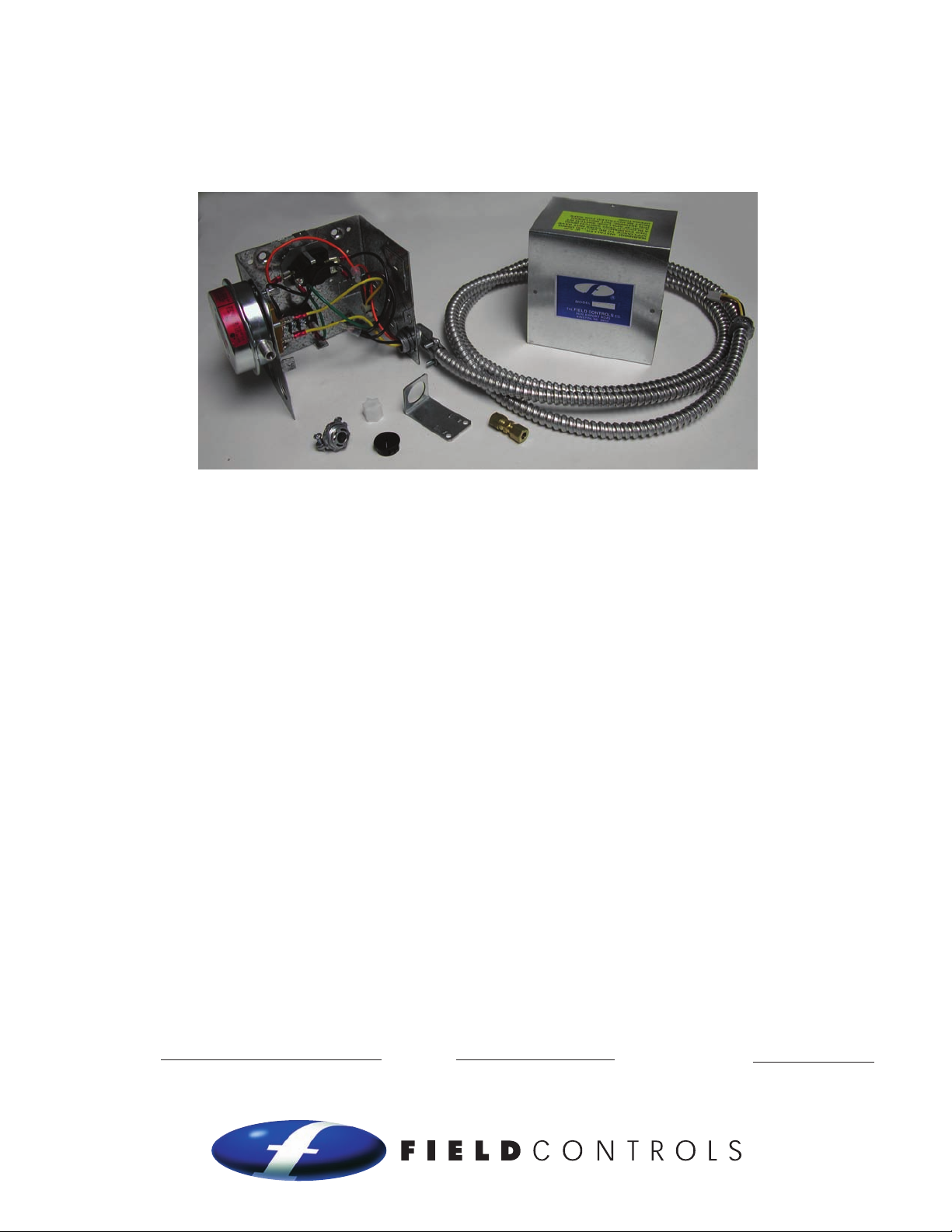
SYSTEM CONTROL KIT
Model: CK-41P
READ THE INSTALLATION INSTRUCTIONS CAREFULLY & COMPLETELY BEFORE BEGINNING THE INSTALLATION!
Designed for use with the SWG Series Power Venter for controlling Natural Gas or L.P. Gas Appliances
equipped with a 24V electric damper. It is designed for modular connection to the appliance controls via
the damper cable connection.
ITEMS INCLUDED IN KIT
1- Control box with mounted pressure switch,
post purge timer and 7" vent damper cable
2- Flexible conduit connector
1
⁄4" tubing connectors
1-
ITEMS NOT INCLUDED IN KIT
1
⁄4" O.D. aluminum, copper or stainless steel tubing
•
• Junction box with connectors and additional circuit
wiring, if required
WARNING: Installer: If the appliance does not have a blocked vent switch, a GSK-3P Spillage Switch Kit,
P/N 46458600, (NOT INCLUDED) must be installed. (See Diagram B)
READ THESE INSTRUCTIONS CAREFULLY AND COMPLETELY BEFORE PROCEEDING WITH THE INSTALLATION.
This device MUST be installed by a qualified agency in accordance with the manufacturer's installation instructions. The definition of
a qualified agency is: any individual, firm, corporation or company which either in person or through a representative is engaged
in, and is responsible for, the installation and operation of HVAC appliances, who is experienced in such work, familiar with all the
precautions required, and has complied with all the requirements of the authority having jurisdiction.
Please retain these instructions after installation.
Installed By: Phone:
www.fieldcontrols.com
Installation Date:
Page 2
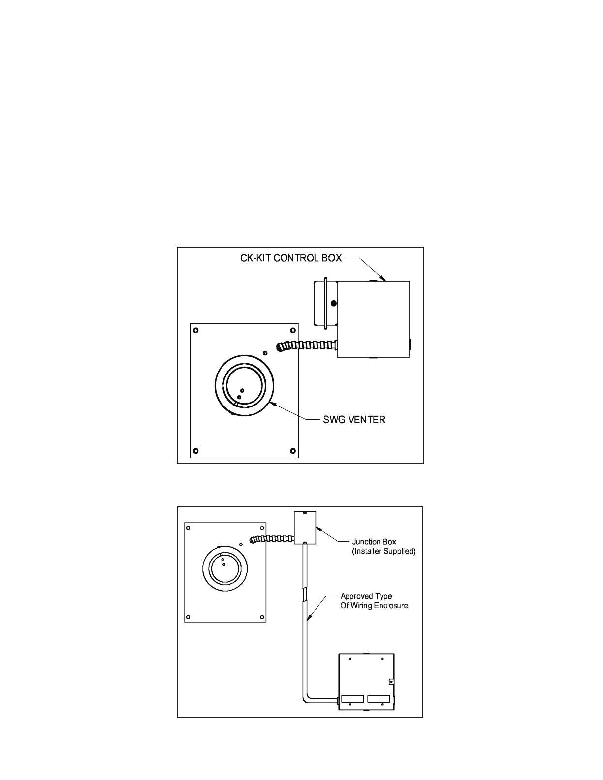
MOUNTING CONTROL BOX
The control box must be mounted within 6' of the vent damper, and within reach of the appliance's existing
damper cable. If the control box must be mounted out of reach of the power venter's attached wiring, an
additional installer supplied junction box and wiring (with approved wiring enclosure if necessary) will be
required. (See Figures 1 & 2)
Install the flexible conduit connector onto the CK-41P control box and secure with fastening nut. If 1.
additional wiring is required, install the flexible conduit connector onto the installer supplied
junction box.
Fasten the flexible conduit from the SWG Venter into the conduit connector. Mount the CK-41P control 2.
box onto a non-heated vertical surface of the appliance or nearby wall or floor joist through the four
dimpled locations on the base of the box. NOTE: The mounted pressure switch diaphragm must be
mounted with a vertical orientation; see label on pressure switch. (See Figure 3) If required, run additional
wiring as in figure 2 and connect to CK-41P control box, if required, using the supplied flexible conduit
connector and approved connectors and anti-short bushings.
page 2
Figure 1
Figure 2
Page 3
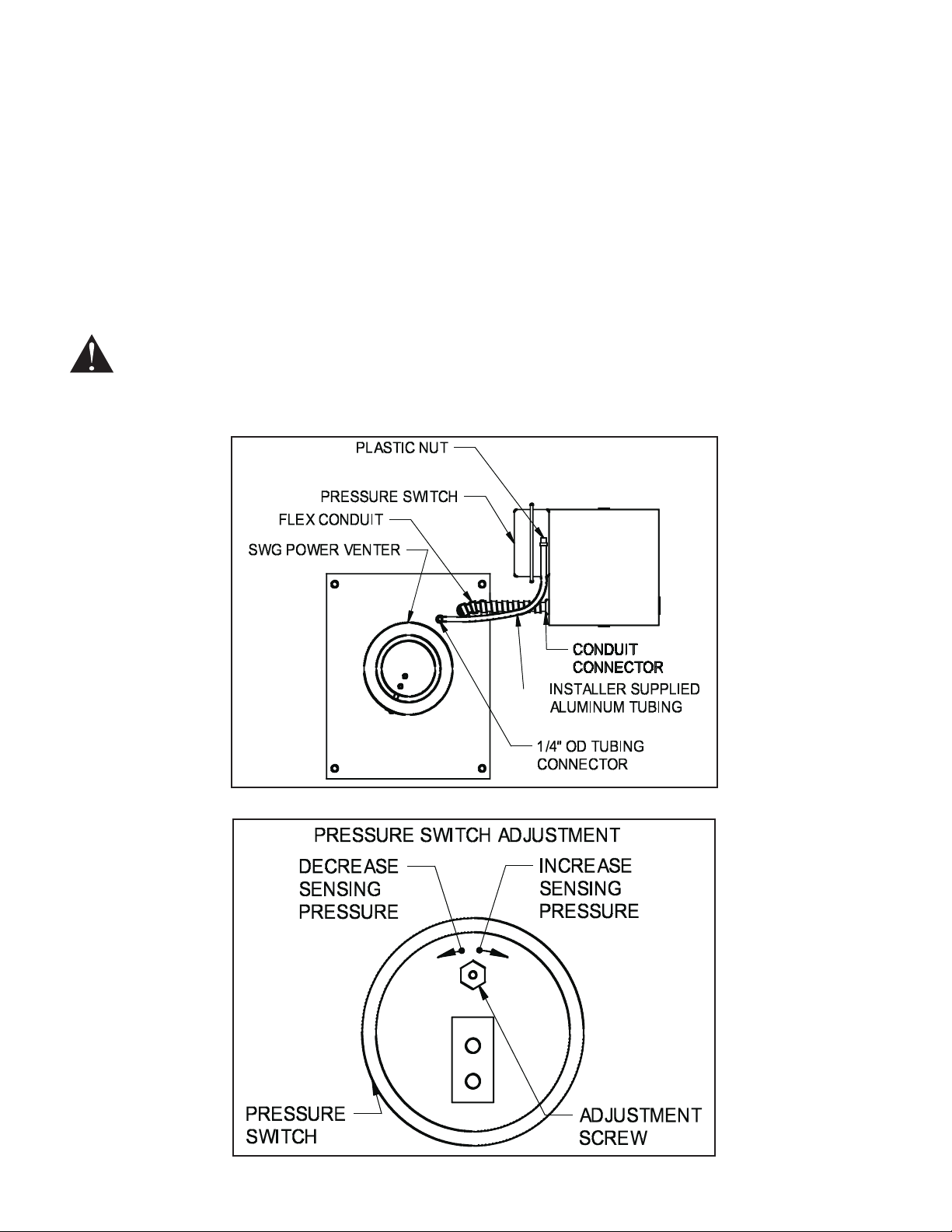
PRESSURE SWITCH SENSING TUBE INSTALLATION
1
Attach the 1.
Connect installer supplied 2.
⁄4" tubing connector to the pressure tube on the SWG Venter. (See Figure 3)
1
⁄4" O.D. aluminum, copper, or stainless steel tubing to the tubing connector.
Route the tubing to the CK-41F junction box and connect the tubing to the pressure switch using supplied 3.
plastic nut. When routing the tubing, avoid kinking the tubing by bending the tubing too sharply. Support
the tubing at 2' intervals using installer supplied tube clamps.
PROVING SWITCH ADJUSTMENTS
After proper air flow is established, the pressure switch adjustment is made by turning the pressure
switch adjustment screw clockwise (See Figure 4) until burner operation stops. Turn the adjustment screw
1
counterclockwise until burner ignites. Turn the adjustment screw an additional
⁄4 to 3⁄4 turn counterclockwise to
ensure adequate switch adjustment.
WARNING: Failure to properly adjust the pressure switch as specified above could lead to improper
operation of the pressure switch, which will result in a hazardous condition and bodily harm!
page 3
Figure 3
Figure 4
Page 4

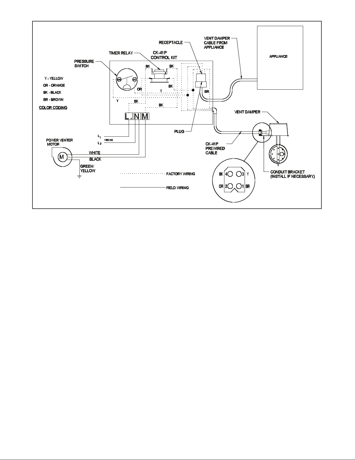
WIRING
CAUTION: Disconnect electrical power when wiring power venter.
Wire the venter motor and controls in accordance with the National Electrical Code, manufacturer’s
recommendations, and/or applicable local codes. Units must be grounded. Check ground circuit to make
certain that the unit has been properly grounded. The wiring should be protected by an overcurrent circuit
device rated at 15 amperes. CAUTION must be taken to ensure that the wiring does not come into contact
with any heat source. All line voltage and safety control circuits between the venter and the appliance MUST
be wired in accordance with the National Electrical Code for class one wiring or equivalent methods. Route
the venter motor and control wiring with an appropriate wiring method. Refer to Wiring Diagrams A and B.
LOW VOLTAGE WIRING INSTRUCTIONS FOR BOILERS
Route the appliance’s vent damper cable to the CK-41P. Plug the cable into the receptacle located inside 1.
the CK-41P using the supplied plastic knockout grommet (if the cable does not have a conduit connector).
(See Diagram A)
Connect the CK-41P’s pre-wired damper cable to the vent damper. (See Diagram A) Snap the end of the 2.
flexible conduit into place on the vent damper conduit bracket.
LINE VOLTAGE WIRING INSTRUCTIONS
Verify that the circuit to be supplying power to the CK-41P is disconnected.1.
Connect the CK-41P green grounding wire to the circuit’s ground wire. Verify that the control box is 2.
properly grounded.
Connect 120 volts hot power source wire to terminal L1 on CK-41P.3.
Connect 120 volts neutral power source wire and white wire from venter motor to terminal N on 4.
the CK-41P.
Connect black wire from venter motor to terminal M on the CK-41P. 5.
Refer to the SWG Venter installation instructions for setting system air flow.
page 4
Page 5
SYSTEM CONTROL CHECK OUT PROCEDURES
Adjust the thermostat and/or aquastat to call for heat and observe the power venting system for proper 1.
operation sequence. Repeat if necessary.
Aquastat calls for heat.a.
After a short delay, the relay is energized, the venter motor starts, and the vent damper b.
begins opening.
Pressure switch closes, the vent damper reaches the open position and the burner starts.c.
Aquastat is satisfied, the burner stops and the vent damper begins closing.d.
This starts the post purge cycle. Purge time 1 to 2 min.e.
While system is operating, disconnect power to the venter motor. This should open the pressure switch 2.
contacts and stop burner operation.
Diagram A
page 5
Page 6

TROUBLE SHOOTING HINTS
Venter does not activate when thermostat calls for heat.1.
Check wiring: 115 VAC from L1 to ground; N connected to a neutral.a.
Check for 24V from orange to black wires on base of timer relay. If no other voltage, the b.
appliance is not calling for heat to the CK-41P. If there is 24 volts continuously for at least 45
seconds, there should be 115 volts from N to M. If not, the time relay is defective, or L1 and N are
not properly wired.
Flue gas odor:2.
Check system draft. Adjust power venter’s airflow adjustment damper if necessary.a.
Check for negative pressure in building.b.
Venter activates but burner does not fire after a minimum of 45 seconds continuous call for heat:3.
Check wiring.a.
Check pressure switch adjustment.b.
Make sure the vent damper is in open position.c.
Check for 24 volts from both yellow wires on pressure switch to black wire on base of timer d.
relay. If neither yellow wire has 24 volts, the vent damper is defective, has loose wiring, or is not
receiving call for heat on the orange wire. If one yellow wire has 24 volts but the other does not,
the pressure switch is not closing.
CAUTION: If for any reason the system has shut down during operation, the cause of the system failure
should be investigated and corrected before resetting the safety switch and restarting the system.
INTERNAL WIRING
Diagram B
L1 TO 1 ON POST PURGE TIMER
M TO 3 ON POST PURGE TIMER
(OTHERS PER HARNESS COLORS)
page 6
Page 7

REPAIR AND REPLACEMENT PARTS LIST
REPAIR AND REPLACEMENT PARTS LIST
DESCRIPTION PART NUMBER
Pressure Switch 46273100
Post Purge Timer 46282800
Wire Harness 46457200
page 7
Page 8

LIMITED WARRANTY
Field Controls, LLC (“Company”) warrants that its products shall be free from defects in material and workmanship
under normal use for the limited period indicated, from the date of manufacture, subject to the provisions 1-8 below.
Eighteen (18) months
All Field Controls Products (except for those listed below as 5 years or 90 days).
Five (5) years
Field Controls Direct Vent Systems (FDVS), Field Oil Vent Kits (FOVP), and ComboVents (CV).
Field Controls warrants that the products listed below shall be free from defects in material and workmanship under
normal use for the limited period indicated, from the date of purchase by the consumer, subject to the provisions
1-8 below.
Ninety (90) days
UV lamps/bulbs
Provisions:
1. During the limited warranty period, Company, or its authorized service representative, will repair or replace, at Company’s
option, without charge, a defective Product. Product that is repaired may be repaired with new or refurbished replacement
parts. Product that is replaced may be replaced with a new or refurbished product of the same or similar design. Company
will return repaired or replacement Product to customer in working condition. Labor charges are not covered as part of the
limited warranty.
2. With regard to UV lamps/bulbs, customer shall be required to include a "valid proof of purchase" (sales receipt) identifying
the Product purchased (Product model or accurate date code information) and the date the Product(s) was purchased.
3. Product whose warranty/quality stickers, Product serial number plates or electronic serial numbers have been removed,
altered or rendered illegible shall not be covered under the limited warranty.
4. Defective Product must be returned to Company, postage prepaid.
5. IN NO EVENT SHALL COMPANY BE LIABLE FOR ANY INDIRECT, SPECIAL, INCIDENTAL, CONSEQUENTIAL, OR SIMILAR
DAMAGES (INCLUDING, BUT NOT LIMITED TO, LOST PROFITS OR REVENUE, INABILITY TO USE PRODUCT, OR OTHER
ASSOCIATED EQUIPMENT, THE COST OF SUBSTITUTE EQUIPMENT, AND CLAIMS BY THIRD PARTIES) RESULTING FROM
THE USE OF PRODUCT. Some states do not allow the exclusion or limitation of incidental or consequential damages, so the
above limitation or exclusion may not apply to you.
6. THIS WARRANTY AND REMEDIES ARE EXCLUSIVE AND IN LIEU OF ALL OTHER WARRANTIES, REMEDIES AND
CONDITIONS, WHETHER ORAL, WRITTEN, EXPRESS, STATUTORY OR IMPLIED. TO THE EXTENT PERMITTED BY LAW,
COMPANY DISCLAIMS ALL IMPLIED AND STATUTORY WARRANTIES, INCLUDING WARRANTIES OF MERCHANTABILITY
AND FITNESS FOR A PARTICULAR PURPOSE.
7. Company makes no warranty of any kind in regard to other manufacturer’s products distributed by Company. Company will
pass on all warranties made by the manufacturer and where possible, will expedite the claim on behalf of the customer, but
ultimately, responsibility for disposition of the warranty claim lies with the manufacturer.
8. Product that has been subjected to misuse, accident, shipping or other physical damage, improper installation or application,
abnormal operation or handling, neglect, fire, water or other liquid intrusion are not covered by the warranty.
© Field Controls, LLC P/N 46457800 Rev C 08/09
Phone: 252.522.3031 • Fax: 252.522.0214
www.fieldcontrols.com
 Loading...