

Page 1

WATER HEATER CONTROL KIT
Model: CK-21
Designed for use on SWG Series Power Venters for controlling Natural
Gas and LP Gas Instantaneous Water Heaters with a pressure tap port.
ITEMS INCLUDED IN KIT:
1- Junction box
1- Fan control gas pressure switch
1
1 1 1- 6 ft length of 12-2 wire
1- 8" jumper wire
1- Flexible conduit connector
2- Spillage Switches
3- Adhesive Tabs
READ THESE INSTRUCTIONS CAREFULLY AND COMPLETELY BEFORE PROCEEDING WITH THE INSTALLATION.
This device MUST be installed by a qualified agency in accordance with the manufacturer's installation instructions. The definition of
a qualified agency is: any individual, firm, corporation or company which either in person or through a representative is engaged
in, and is responsible for, the installation and operation of HVAC appliances, who is experienced in such work, familiar with all the
precautions required, and has complied with all the requirements of the authority having jurisdiction.
Please retain these instructions after installation.
Installed By: Phone:
⁄8" NPT x 3" pipe nipple
1
⁄8" NPT pipe tee
Installation Date:
www.fieldcontrols.com
Page 2
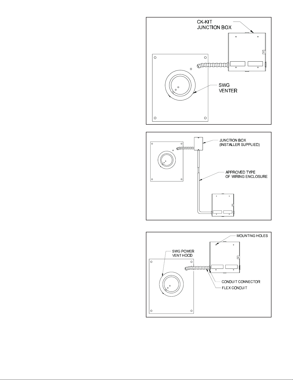
MOUNTING JUNCTION BOX
The junction box can be mounted at the venter or
remotely mounted away from the venter.
(See Figure 1 & Figure 2)
Remove one of the knockouts from the side of 1.
the junction box where the pressure switch is
mounted. Install the flexible conduit connector
onto the CK-21 junction box and secure with
fastening nut. If remote mounting the
CK-21 junction box, mount the flexible conduit
connector onto a 2" x 4" installer supplied
junction box.
Fasten the flexible conduit from the SWG Venter 2.
into the conduit connector. Mount the CK-21
junction box or installer supplied junction box
onto the wall or floor joist without straining the
flexible conduit. Fasten the CK-21 junction box
through the four dimpled locations on the base
of the box. (See Figure 3)
Figure 1
Figure 2
Figure 3
page 2
Page 3
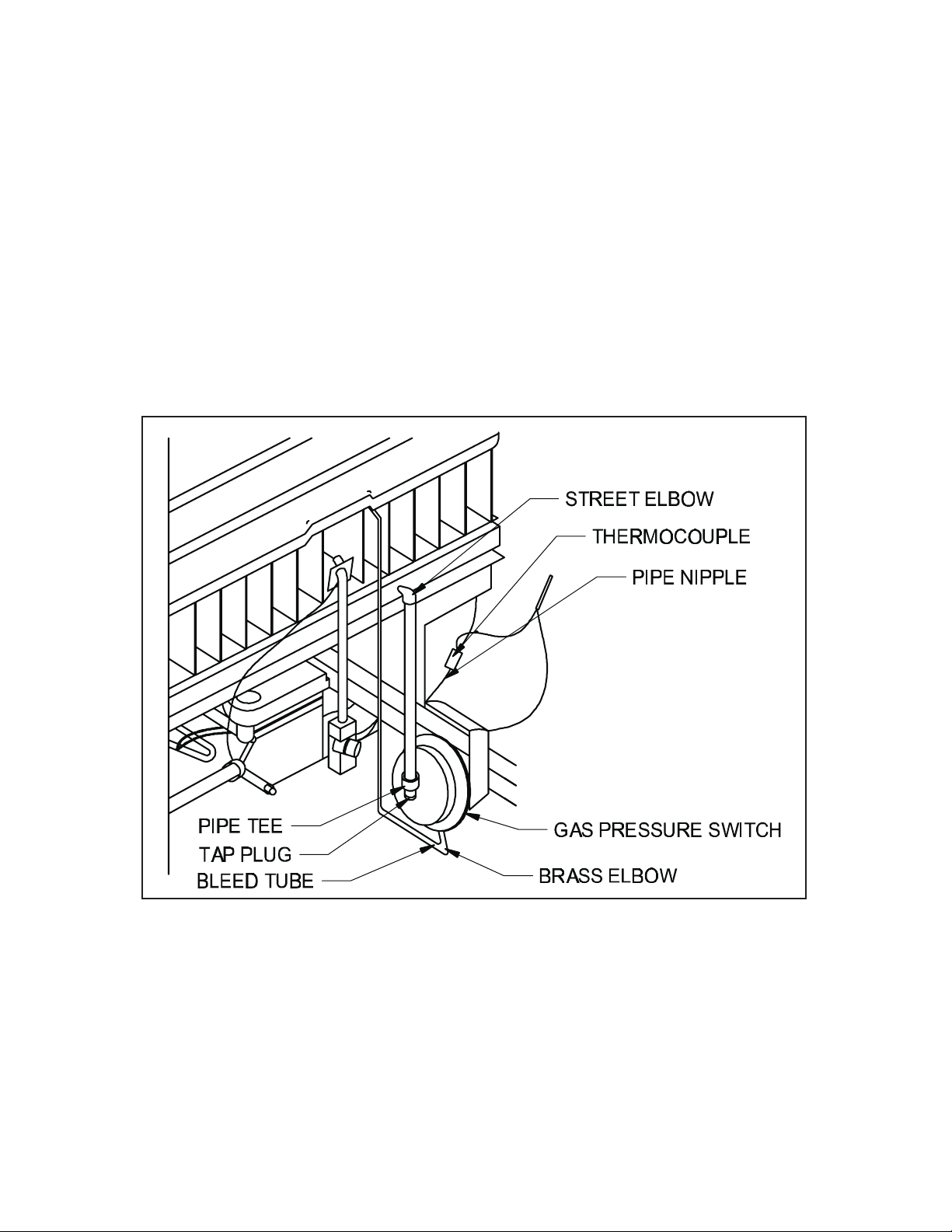
INSTALLATION OF GAS PRESSURE SWITCH
CAUTION: Maximum gas pressure MUST NOT exceed 14" W.C. Pressure. Gas supply must be shut off
before working on piping systems.
NOTE: Seal all pipe connections with pipe thread sealant.
Remove pressure tap plug in manifold.1.
1
Install 2.
pressure tap plug. Then install the 3" x
⁄8" NPT Street elbow (if required for mounting the gas pressure switch vertically) in place of the
1
⁄8" NPT nipple, pipe tee and pressure tap plug. (See Figure 4)
Install the gas pressure switch into the side of the pipe tee. Position the switch vent, on the side of the 3.
switch, down.
CAUTION: If for any reason the system has shut down during operation, the cause of the system failure should
be investigated and corrected before resetting the safety switch and restarting the system.
NOTE: Gas Pressure Switch MUST be mounted vertically.
page 3
Figure 4
Page 4

INSTALLATION OF SAFETY SPILLAGE SWITCHES
NOTE: Water Heater MUST have safety switches installed.
Installation of a SAFETY SWITCH is REQUIRED for water
heaters, for the purpose of detecting spillage from a blocked
flue system and/or inadequate draft.
Bend the tab attached to the spillage switches as shown 1.
in Figure 5.
Mount the spillage switches along the opening of the 2.
draft hood. (See Figure 6) Connect one terminal on
each spillage switch with the 8" jumper wire. Then
connect the other two terminals to the jacketed wire.
Route the jacketed wire along the frame or enclosure
of the water heater, keeping the wires away from any
HOT surface area. Secure the wire with adhesive tabs.
(See Figure 6)
Splice the jacketed wire in series with one of the leads 3.
connected to the thermocouple splicing terminal.
(See Figure 6)
CAUTION: If for any reason the system has shut down
during operation, the cause of the system failure should be
investigated and corrected before resetting the safety switch
and re-starting the system.
Figure 5
page 4
Figure 6
Page 5

WIRING
Wire the venter motor and controls in accordance with the National Electrical Code, manufacturer’s
recommendations and/or applicable local codes. UNIT MUST BE GROUNDED. Check ground circuit to make
certain that the unit has been properly grounded. The wiring should be protected by an over current device
rated at 15 amperes. CAUTION must be taken to ensure that the wiring does not come into contact with any
heat source. All line voltage and safety control circuits between the venter and the appliance must be wired in
accordance with the National Electrical Code for Class I wiring or equivalent methods.
Route the venter motor and control wiring with an appropriate wiring method. Refer to Wiring Diagram A.
Refer to SWG Venter Installation Instructions for setting system airflow.
page 5
Diagram A
Page 6

SYSTEM CHECK-OUT PROCEDURE FOR HOT WATER HEATER CONTROLS
WATER HEATER GAS PRESSURE SWITCH
Following water heater manufacturer's instructions to light the pilot, turn the gas control valve to the 1.
ON position.
Open the hot water faucet; this should energize the venter. Next, close the hot water faucet; this 2.
should de-energize the venter.
Repeat Step 2 to assure proper operation.3.
SAFETY SPILLAGE SWITCHES
Allow water heater to heat up to operating temperature by opening the hot water faucet, then 1.
disconnect the power supply to the venter.
Allow approximately 2 minutes for the spillage switches to sense the spillage of flue gas and 2.
de-energize the thermocouple circuit. This will halt the gas flow to the pilot and burner.
Wait 2 or 3 minutes, reset spillage switches and relight pilot. Then perform a second spillage test 3.
(Steps 1 and 2).
TROUBLE SHOOTING HINTS
Venter does not activate when hot water faucet is opened.1.
Check wiring.a.
Check gas pressure switch for continuity across terminals when gas valve is pressurized.b.
Check gas pressure.c.
Check amount of water flow.d.
Flue gas odor.2.
Check system draft.a.
Check for negative pressure in building.b.
Pilot will not stay lit.3.
Solder all spillage switch wire terminal connections.a.
Check reset buttons on spillage switches.b.
MAINTENANCE
Motor:1. Inspect motor once a year, the motor should rotate freely.
Wheel:2. Inspect venter wheel annually to clear any soot, ash or coating, which inhibits either rotation or
air flow. Remove all foreign material before operating.
Vent System:3. Inspect all vent pipe connections annually for looseness and for evidence of flue gas
leakage. Seal or tighten pipe connections if necessary.
page 6
Page 7

LIMITED WARRANTY
Field Controls, LLC (“Company”) warrants that its products shall be free from defects in material and workmanship
under normal use for the limited period indicated, from the date of manufacture, subject to the provisions 1-8 below.
Eighteen (18) months
All Field Controls Products (except for those listed below as 5 years or 90 days).
Five (5) years
Field Controls Direct Vent Systems (FDVS), Field Oil Vent Kits (FOVP), and ComboVents (CV).
Field Controls warrants that the products listed below shall be free from defects in material and workmanship under
normal use for the limited period indicated, from the date of purchase by the consumer, subject to the provisions
1-8 below.
Ninety (90) days
UV lamps/bulbs
Provisions:
1. During the limited warranty period, Company, or its authorized service representative, will repair or replace, at Company’s
option, without charge, a defective Product. Product that is repaired may be repaired with new or refurbished replacement
parts. Product that is replaced may be replaced with a new or refurbished product of the same or similar design. Company
will return repaired or replacement Product to customer in working condition. Labor charges are not covered as part of the
limited warranty.
2. With regard to UV lamps/bulbs, customer shall be required to include a "valid proof of purchase" (sales receipt) identifying
the Product purchased (Product model or accurate date code information) and the date the Product(s) was purchased.
3. Product whose warranty/quality stickers, Product serial number plates or electronic serial numbers have been removed,
altered or rendered illegible shall not be covered under the limited warranty.
4. Defective Product must be returned to Company, postage prepaid.
5. IN NO EVENT SHALL COMPANY BE LIABLE FOR ANY INDIRECT, SPECIAL, INCIDENTAL, CONSEQUENTIAL, OR SIMILAR
DAMAGES (INCLUDING, BUT NOT LIMITED TO, LOST PROFITS OR REVENUE, INABILITY TO USE PRODUCT, OR OTHER
ASSOCIATED EQUIPMENT, THE COST OF SUBSTITUTE EQUIPMENT, AND CLAIMS BY THIRD PARTIES) RESULTING FROM
THE USE OF PRODUCT. Some states do not allow the exclusion or limitation of incidental or consequential damages, so the
above limitation or exclusion may not apply to you.
6. THIS WARRANTY AND REMEDIES ARE EXCLUSIVE AND IN LIEU OF ALL OTHER WARRANTIES, REMEDIES AND
CONDITIONS, WHETHER ORAL, WRITTEN, EXPRESS, STATUTORY OR IMPLIED. TO THE EXTENT PERMITTED BY LAW,
COMPANY DISCLAIMS ALL IMPLIED AND STATUTORY WARRANTIES, INCLUDING WARRANTIES OF MERCHANTABILITY
AND FITNESS FOR A PARTICULAR PURPOSE.
7. Company makes no warranty of any kind in regard to other manufacturer’s products distributed by Company. Company will
pass on all warranties made by the manufacturer and where possible, will expedite the claim on behalf of the customer, but
ultimately, responsibility for disposition of the warranty claim lies with the manufacturer.
8. Product that has been subjected to misuse, accident, shipping or other physical damage, improper installation or application,
abnormal operation or handling, neglect, fire, water or other liquid intrusion are not covered by the warranty.
page 7
Page 8

Phone: 252.522.3031 • Fax: 252.522.0214
www.fieldcontrols.com
© Field Controls, LLC P/N 46159000 Rev C 08/09
 Loading...