

Page 1

120 VAC SYSTEM CONTROL KIT
Model: CK-63
Designed for use on SWG Series Power Vent Hoods for controlling oil fired heating appliances
with 120 VAC controls.
The CK-63 control has the ability to operate the oil burner motor (up to
1
⁄3 HP) and the venter at the
same time. This allows for shorter post purge time. This feature requires the burner to be equipped
with a delayed oil solenoid valve, which is not supplied with this kit.
ITEMS INCLUDED IN KIT:
1- Junction box with mounted pressure switch solid state post purge control
1
1- 2' Length of
1
⁄4" tubing connector
1-
⁄4" aluminum tubing
1- Flexible conduit connector
1- WMO-1 Blocked Vent Switch
READ THESE INSTRUCTIONS CAREFULLY AND COMPLETELY BEFORE PROCEEDING WITH THE INSTALLATION.
This device MUST be installed by a qualified agency in accordance with the manufacturer's installation instructions. The definition of
a qualified agency is: any individual, firm, corporation or company which either in person or through a representative is engaged
in, and is responsible for, the installation and operation of HVAC appliances, who is experienced in such work, familiar with all the
precautions required, and has complied with all the requirements of the authority having jurisdiction.
Please retain these instructions after installation.
Installed By: Phone:
www.fieldcontrols.com
Installation Date:
Page 2
INSTALLATION
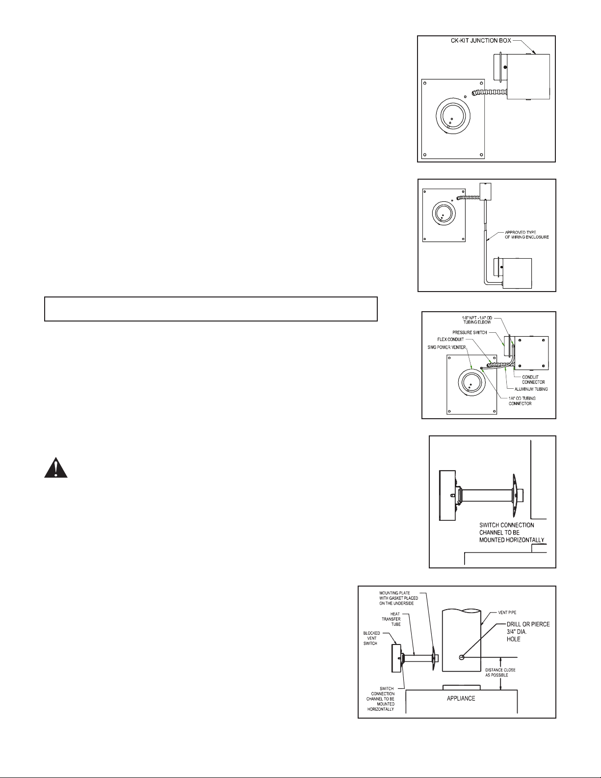
MOUNTING JUNCTION BOX
The junction box can be mounted at the venter or remotely mounted away
from the venter. (See Figure 1 & Figure 2)
Remove one of the knockouts from the side of the junction box where the 1.
pressure switch is mounted. Install the flexible conduit connector onto the
CK-63 junction box and secure with fastening nut. If remote mounting the
CK-63 junction box, mount the flexible conduit connector onto a 2" x 4"
installer supplied junction box.
Fasten the flexible conduit from the SWG Venter into the conduit 2.
connector. Mount the CK-63 junction box or installer supplied junction
box onto the wall or floor joist without straining the flexible conduit.
Fasten the CK-63 junction box through the four dimpled locations on the
base of the box. (See Figure 3)
OIL FIRED SECONDARY SAFETY SWITCH
Installation of a SECONDARY SAFETY SWITCH is recommended for detecting
a blocked flue system and/or inadequate draft.
MOUNTING IN THE VENT PIPE
SEE THE APPLIANCE MANUFACTURER’S INSTRUCTIONS FOR THE SPECIFIC LOCATION.
IF THE APPLIANCE MANUFACTURER DOES NOT SPECIFY A LOCATION, REFER TO FIGURE 5.
3
Drill or pierce a clean hole (about 1.
⁄4" diameter) in the vent pipe near the
appliance outlet. (See Figure 5)
The heat transfer tube must have the fiber gasket installed against the 2.
mounting plate before attaching the unit to the vent pipe.
3
Insert the heat transfer tube with gasket into the 3.
⁄4" diameter hole placed
in the vent pipe during step 1.
Secure the assembly to the vent pipe with a minimum of 4 sheet metal 4.
screws. The channel must be mounted horizontally, unless specified
differently by the appliance manufacturer. (See Figure 5)
Figure 1
Figure 2
Figure 3
WARNING: Switch connection channel must be mounted horizontally,
unless specified differently by the appliance manufacturer.
CAUTION: Disconnect electrical power supply to the appliance when wiring
the blocked vent switch.
PRESSURE SWITCH SENSING TUBE INSTALLATION
1
Attach the 1.
⁄4" tubing connector to the pressure tube on the SWG Venter.
(See Figure 3)
1
Connect the supplied 2.
⁄4" aluminum tubing to the tubing
connector. Route the tubing to the CK-63 junction box and
connect the tubing to the pressure switch. When routing the
tubing avoid kinking the tubing by bending the tubing
too sharply.
1
For remote mounted CK-63 junction box, use a 3.
⁄4" OD
copper, aluminum, or plastic tubing and route the tubing to
avoid contact with any heat source.
Refer to the SWG Venter installation instructions for setting
system airflow.
page 2
Figure 4
Figure 5
Page 3
WIRING INSTRUCTIONS
Wire the venter motor and controls in accordance with the National Electrical Code, manufacturer's
recommendations and/or applicable local codes. UNIT MUST BE GROUNDED. Check ground circuit to make
certain that the unit has been properly grounded. The wiring should be protected by an over current circuit
device rated at 15 amperes. Caution must be taken to ensure that the wiring does not come into contact with
any heat source. All line voltage and safety control circuits between the venter and the appliance MUST be
wired in accordance with the National Electrical Code for Class I wiring or equivalent methods.
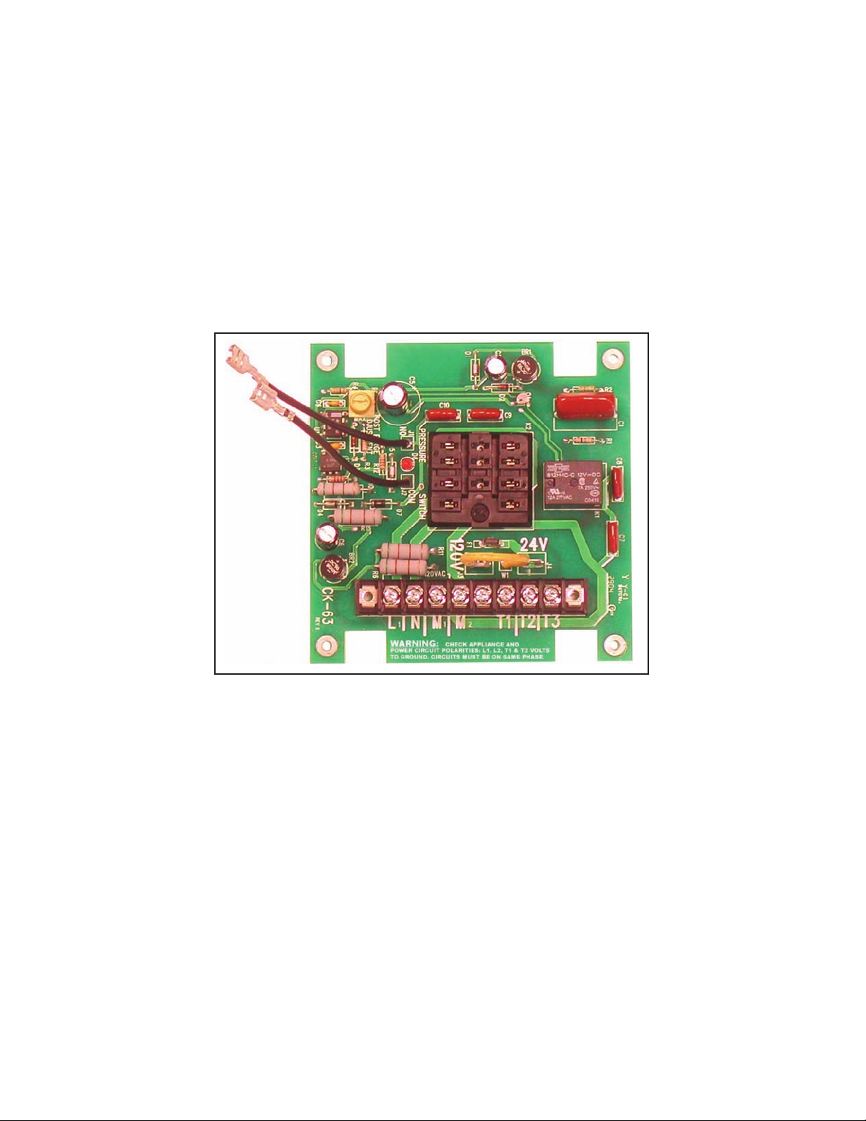
Route the venter motor and control wiring with an appropriate wiring method. (Diagrams A through H)
NOTE: Control is factory set for 120V wiring. For 24V wiring connect the yellow mode wire to the
24V terminal.
NOTE: Circuit board is polarity sensitive. Follow check-out procedures.
Figure 6- Close-Up of Interior Board Layout
page 3
Page 4
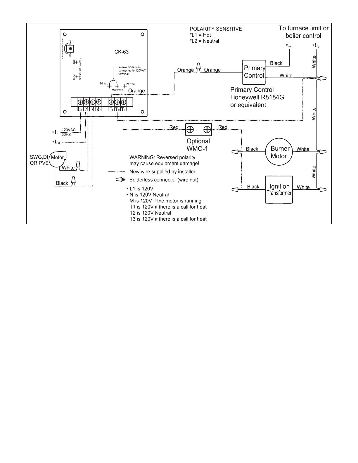
Diagram A - Oil Fired System: Single Unit Wiring
page 4
Page 5
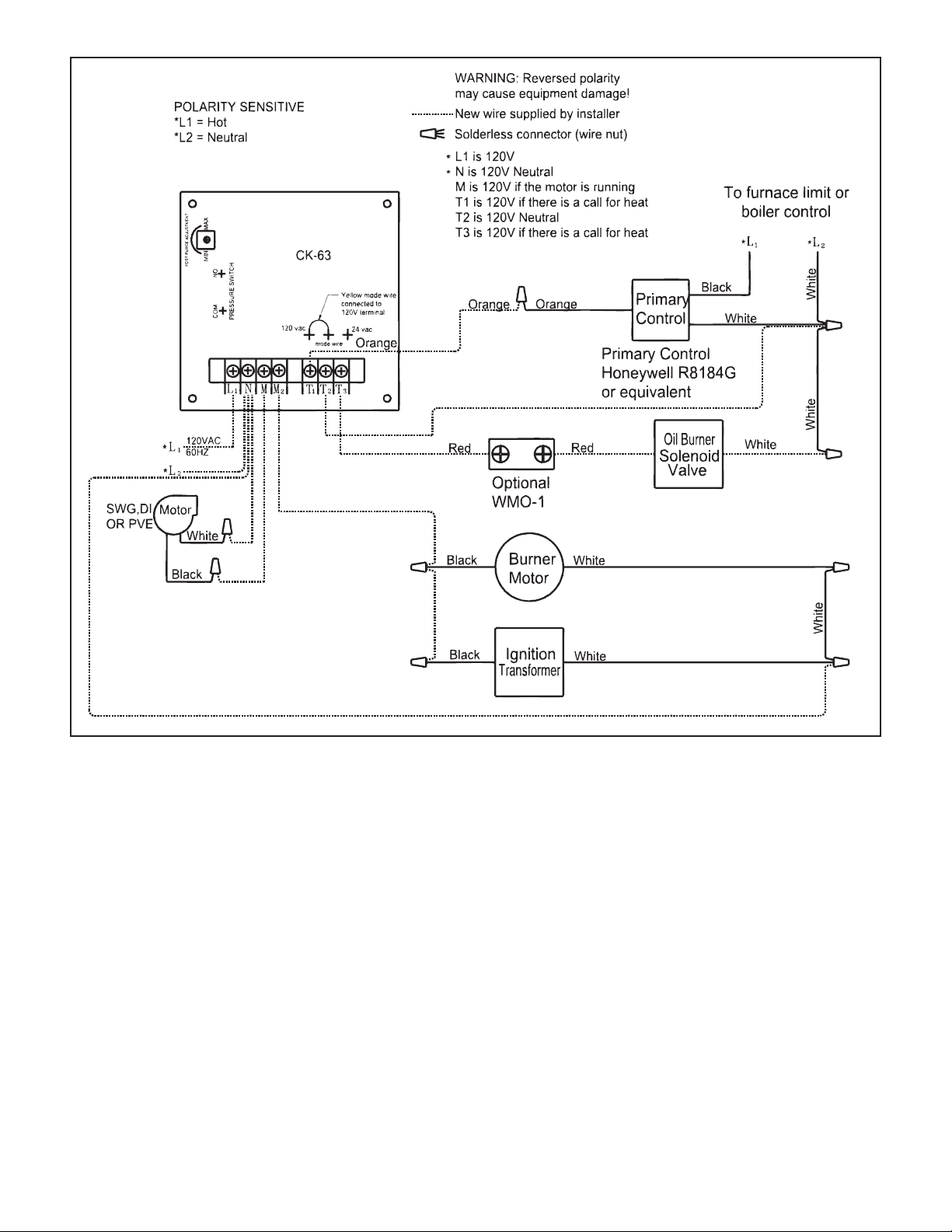
Diagram B - Oil Fired System: Simultaneous Burner Wiring
page 5
Page 6

Diagram C - Oil Fired System: Wiring With Electronic Primary
page 6
Page 7

Diagram D - Oil Fired System: Simultaneous Burner Wiring With Electronic Primary
page 7
Page 8

page 8
Diagram E - Typical Wiring for Oil Fired Warm Air
Furnace with a Honeywell ST9103 Control Board
Page 9

page 9
Diagram F - Multiple Oil Fired Systems
Page 10

Diagram G - 24V Gas Furnace Application
page 10
Page 11

Diagram H - Riello Burner Application
page 11
Page 12

ADJUSTMENTS
PRESSURE SWITCH ADJUSTMENTS
With the venter air flow set and the appliance operating
at the best operating efficiency, adjust the pressure
switch by rotating the adjustment screw clockwise
until the burner shuts off, then rotate the adjustment
screw counterclockwise until the burner fires. Rotate
1
the adjustment screw an additional
⁄4 to 1⁄2 turn
counterclockwise to ensure proper switch setting.
(See Figure 7)
POST PURGE TIMING ADJUSTMENT
To adjust the post purge time, rotate the timer adjustment
on the timer clockwise to increase
the operation time. To decrease the
operation time, rotate the timer adjustment
counterclockwise. (See Figure 8) Typical
post purge time should be between 3 to 5
minutes. If running burner simultaneous with
venter, 1-3 minutes is suggested.
SYSTEM CONTROL CHECK
OUT PROCEDURES
Adjust the thermostat to call for heat 1.
and observe the power venting system
for proper operation sequence (repeat
if necessary).
Thermostat calls for heat.a.
Relay is energized and venter b.
motor starts.
Pressure switch closes and burner c.
starts. The LED light indicates power
to T3. When the pressure switch
closes with a call for heat, the LED
light will come on. This indicates
that the burner should be in a burn cycle. (See Figure 8)
Thermostat is satisfied, burner stops and venter motor should operate for the set post purge time. The d.
LED should not be on during the post purge.
While system is operating, disconnect power to the venter motor. This should open the pressure switch 2.
contacts and stop burner operation.
(If WMO-1 switch is installed) Allow vent system to cool. Disconnect the vent pipe between the venter 3.
inlet and the appliance outlet. Block the vent pipe with a noncombustible material. Activate the heating
system with the main burner operating. Allow approximately 2 minutes or less for the secondary safety
switch to deactivate the burner. Reset safety switch after waiting 15 minutes for WMO-1 to cool down
and repeat.
Figure 7
Figure 8
YEARLY MAINTENANCE PROCEDURE FOR POWER VENTER
Motor: Inspect motor once a year; the motor should rotate freely. Lubricate motor with 6 drops of SWG
Superlube in each oil port hole annually.
Wheel: Inspect venter wheel annually, for oil fired heating systems, clear any soot, ash or coating, which
inhibits either rotation or air flow. Remove all foreign material before operating.
Vent System: Inspect all vent pipe connections annually for looseness and for evidence of flue gas leakage.
Seal or tighten pipe connections if necessary.
page 12
Page 13

TROUBLESHOOTING HINTS
Main burner does not fire when thermostat calls for heat with venter operating.1.
Check pressure switch adjustment. (LED should be lit when there is voltage from T1 – T2 and the pressure a.
switch is closed.)
Check fuel flow.b.
Check wiring connections between pressure switch and burner and yellow mode wire connection.c.
Check pressure switch for continuity across terminals, during venter operation.d.
Venter does not activate when thermostat calls for heat.2.
Jump wire the terminals L1 and M to ensure motor operation.a.
Check wiring connections including yellow mode wire.b.
Flue gas odor.3.
Check system draft.a.
Check post purge venting time.b.
Check for negative pressure in building.c.
Power venter cycling.4.
Check voltage between T1 and T2 and refer to Wiring Check-Out Standard Set-up (see below).a.
Use resistor between T1 (120V) and T2 for bleed voltage.b.
REPLACEMENT PARTS LIST
Description Part Number
Pressure Switch 46273100
Board Replacement Kit
(includes relay)
WMO -1 46086900
4 6 474 3 0 0
page 13
Page 14

CK-63 Wiring Aquastat Relay Check-Out
page 14
Page 15

BASIC TESTS:
Using your meter, check voltage between L1 and 1.
ground. You should have 120 volts all the time. If
you do not have 120 volts all the time, your wiring
is wrong or your breaker is off.
Using your meter, check the voltage between T1 2.
and T2. You should have 120 volts (24V for lowvoltage controls) when there is a call for heat. If
you do not have the appropriate voltage when
there is a call for heat, your wiring is wrong or
your primary control is faulty.
Using your meter, check the voltage between T2 3.
and T3. You should only have 120 volts (24V for
low-voltage controls) when the power venter is
running and there is a call for heat. If you do not
have the appropriate voltage when the power
venter is running and there is a call for heat,
the pressure switch is not closing or is defective:
perform the pressure switch adjustment procedure;
if the switch will not close, check the sensing tube
and tube connections.
page 15
CK-63 Wiring Check-Out Standard Set-up
Page 16

LIMITED WARRANTY
Field Controls, LLC (“Company”) warrants that its products shall be free from defects in material and workmanship
under normal use for the limited period indicated, from the date of manufacture, subject to the provisions 1-8 below.
Eighteen (18) months
All Field Controls Products (except for those listed below as 5 years or 90 days).
Five (5) years
Field Controls Direct Vent Systems (FDVS), Field Oil Vent Kits (FOVP), and ComboVents (CV).
Field Controls warrants that the products listed below shall be free from defects in material and workmanship under
normal use for the limited period indicated, from the date of purchase by the consumer, subject to the provisions
1-8 below.
Ninety (90) days
UV lamps/bulbs
Provisions:
1. During the limited warranty period, Company, or its authorized service representative, will repair or replace, at Company’s
option, without charge, a defective Product. Product that is repaired may be repaired with new or refurbished replacement
parts. Product that is replaced may be replaced with a new or refurbished product of the same or similar design. Company
will return repaired or replacement Product to customer in working condition. Labor charges are not covered as part of the
limited warranty.
2. With regard to UV lamps/bulbs, customer shall be required to include a "valid proof of purchase" (sales receipt) identifying
the Product purchased (Product model or accurate date code information) and the date the Product(s) was purchased.
3. Product whose warranty/quality stickers, Product serial number plates or electronic serial numbers have been removed,
altered or rendered illegible shall not be covered under the limited warranty.
4. Defective Product must be returned to Company, postage prepaid.
5. IN NO EVENT SHALL COMPANY BE LIABLE FOR ANY INDIRECT, SPECIAL, INCIDENTAL, CONSEQUENTIAL, OR SIMILAR
DAMAGES (INCLUDING, BUT NOT LIMITED TO, LOST PROFITS OR REVENUE, INABILITY TO USE PRODUCT, OR OTHER
ASSOCIATED EQUIPMENT, THE COST OF SUBSTITUTE EQUIPMENT, AND CLAIMS BY THIRD PARTIES) RESULTING FROM
THE USE OF PRODUCT. Some states do not allow the exclusion or limitation of incidental or consequential damages, so the
above limitation or exclusion may not apply to you.
6. THIS WARRANTY AND REMEDIES ARE EXCLUSIVE AND IN LIEU OF ALL OTHER WARRANTIES, REMEDIES AND
CONDITIONS, WHETHER ORAL, WRITTEN, EXPRESS, STATUTORY OR IMPLIED. TO THE EXTENT PERMITTED BY LAW,
COMPANY DISCLAIMS ALL IMPLIED AND STATUTORY WARRANTIES, INCLUDING WARRANTIES OF MERCHANTABILITY
AND FITNESS FOR A PARTICULAR PURPOSE.
7. Company makes no warranty of any kind in regard to other manufacturer’s products distributed by Company. Company will
pass on all warranties made by the manufacturer and where possible, will expedite the claim on behalf of the customer, but
ultimately, responsibility for disposition of the warranty claim lies with the manufacturer.
8. Product that has been subjected to misuse, accident, shipping or other physical damage, improper installation or application,
abnormal operation or handling, neglect, fire, water or other liquid intrusion are not covered by the warranty.
© Field Controls, LLC P/N 46400900 Rev L 08/09
Phone: 252.522.3031 • Fax: 252.522.0214
www.fieldcontrols.com
 Loading...