

Page 1
SPECIAL VENTING APPLICATION
INSTALLATION SHEET FOR
AQUAHUT® WATER HEATER ENCLOSURES
This sheet covers the requirements for installing the Star-Kap™ on an Aquahut® gas water heater
enclosure. The Aquahut® enclosure is designed for the purpose of housing a gas water heater
outside of the living space of a structure. These requirements are based on the A.G.A. test reports
C-FT-5-90, C-FT-8-90, FT -C-12-93, FT-C-13 -93, FT-C-14-92 and the SBCCI letter dated May 24,
1990. The Aquahut® water heater enclosure is not sold or manufactured by the Field Controls Co.
These installation instructions only address the installation of the Star-Kap™, state the maximum
capacity water heater allowed in an Aquahut® and the vent termination clearances from windows or
openings into a building structure as tested in the A.G.A. field reports C-FT-5-90, C-FT-8-90, FT-C12-93, FT-C-13-93, FT-C-14-92 and the SBCCI letter dated May 24, 1990.
INSTALLATION GUIDE LINES
1. The maximum gas water heater appliance to be operated in a Aquahut® enclosure: up to 90,000
BTU/HR input.
2. Two (2) make up/combustion air openings into the Aquahut® enclosure shall be installed. Each
opening size shall be based on one (1) square inch per 4000 BTU/HR. The vent termination shall
have the following clearance distances.
a. AH40 Model Aquahut®
14” from combustible exterior wall to center of vent cap
b. AH50 Model Aquahut®
16” from combustible exterior wall to center of vent cap
c. A minimum of 12” from any window or opening into the main building structure
d. A minimum of 18” below an eave or overhang
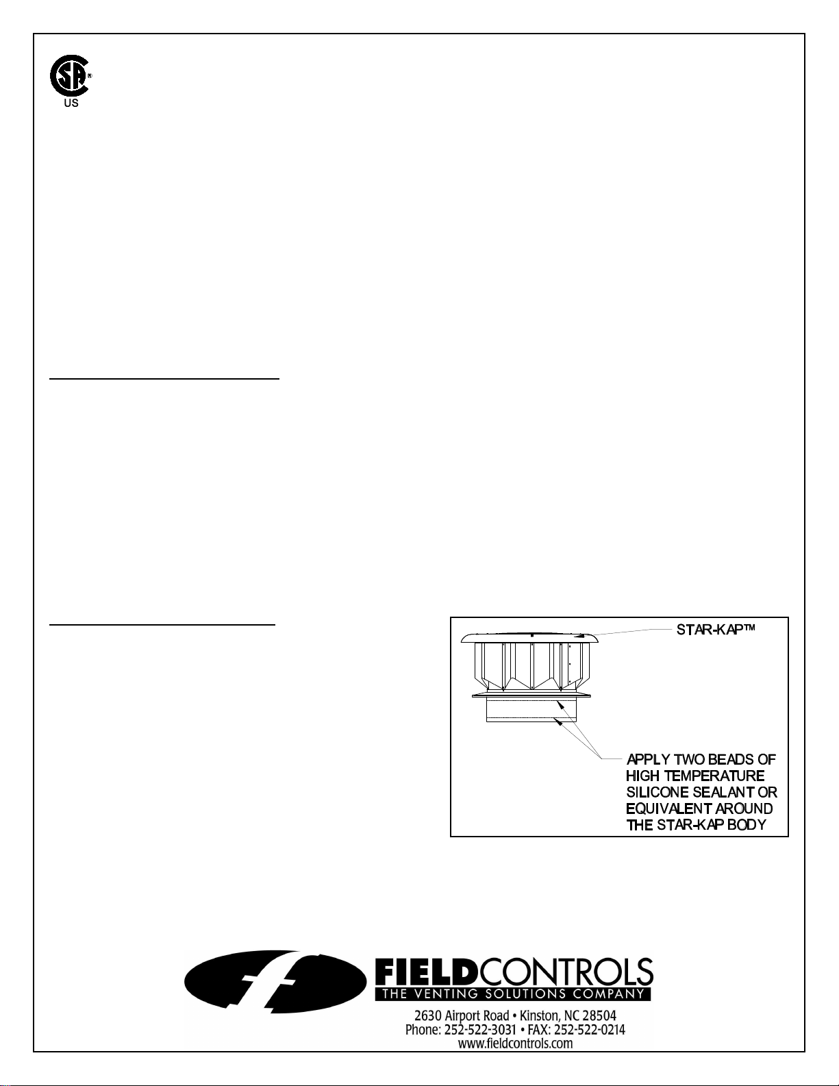
STAR-KAP™ INSTALLATION
1. Before installation, apply two (2) beads of high
temperature silicone sealant or equivalent around
the bottom of the storm collar and one (1) inch
above the end of the Star-Kap™ body. (See
Figure 1)
2. Insert the Star-Kap™ into the inside of the single
wall vent pipe, making sure the Star-Kap™ is
seated against the storm collar. Fasten the StarKap™ to the single wall vent pipe, by using
three (3) sheet metal screws. Placement of the
screws should be approximately 1/2 inch from
the end of the single wall vent pipe. The heads
of the screws should be covered with high
temperature silicone or equivalent.
Figure 1
P/N 46263400 Rev D 11/00
 Loading...