

Page 1
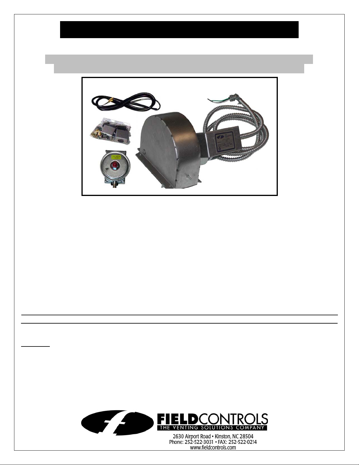
DRAFT INDUCER KIT WITH CONTROL KIT
Model: DI PAK MV & DI PAK MVFG
(NOTE: DI PAK MVFG units are designed for the Flame Guard units built
by American Water Heater. All other manufacturers use DI PAK MV)
This draft inducer kit is designed for installation onto vent systems serving
30 millivolt standing pilot gas fired water heaters with gas valves having a
manifold pressure tap port (1/8 FPT)
NOTE: DI-1 Model must be used on 4” diameter vent pipe.
I
TEMS INCLUDED IN KIT
1) DI-1,2 or 3 Draft Inducer with pre-attached power cable
1) Fan control gas pressure switch with built in post purge option and pre-wired power cord
1) 1/8" NPT x 3 inch pipe nipple
1) 1/8" NPT pipe tee
1) TCA-1 Thermocouple Adapter (DI PAK MV)
1) TCA-2 Left Handed Thermocouple Adapter (DI PAK MVFG)
1) 6 ft. length of 12-2 wire
1) 12 inch jumper wire
1) Flexible conduit connector
2) GSK-3 Spillage Switch
DO NOT DESTROY
THESE INSTRUCTIONS MUST REMAIN WITH EQUIPMENT
CAUTION:
This device is NOT designed for sidewall venting applications. The vent to which the inducer is to be mounted is to be
installed in accordance with NFPA 54, NFPA 31, or other local codes.
This device MUST be installed by a qualified installer in accordance with the manufacturers installation instructions.
Appliances should have a maximum measure flue gas temperature of 750°F at the desired location of the draft inducer.
“Qualified Installer” shall mean an individual who has been properly trained or a licensed installer. The installer MUST
write or imprint his name, phone number, and date of installation on the tag provided with this device. The tag MUST be
attached to the draft inducer. Recording burner and draft inducer operation information (draft level, efficiency, etc) is
recommended as a guide for future service.
Draft inducers are designed to increase draft in venting applications where inadequate natural draft exists.
Page 2
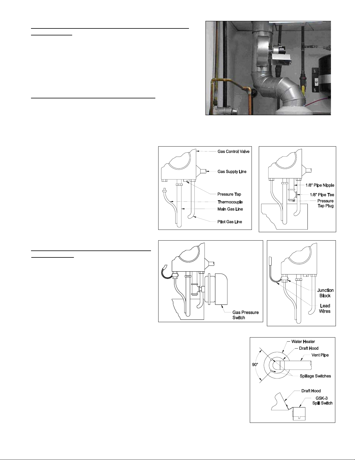
I. INSTALL THE DI-SERIES DRAFT INDUCER ON THE FLUE
PIPE (Figure 1)
1. Refer to the included DI instruction manual for this
procedure. Set the draft adjustment plate on the draft
inducer to maximum setting before installing
NOTE: The draft inducer proving switch (DIP-1) and DI-CK
Control Kit adapter kit are not required with the DI PAK MV and
MVFG kits.
II. INSTALLATION OF GAS PRESSURE SWITCH
CAUTION: Check gas control valve pressure. Pressure must not
exceed 14" WC pressure.
1. Remove pressure tap plug in gas valve. (See Figure 2)
Figure 1
NOTE: If installing on an existing appliance, shut off gas supply to
gas valve before plug removal.
2. Replace the pressure tap plug with the 1/8" pipe nipple and pipe tee. Install pressure tap plug at the bottom of the
pipe tee. (See Figure 3)
3. Install the gas pressure switch into the side of
the pipe tee. The gas pressure switch is
supplied with a restrictor orifice in the inlet and
outlet ports. With these orifices in place, the
switch does not need to be vented. This
feature complies with current ANSI standards
for gas regulators. (See Figure 4)
CAUTION: If for any reason the system has shut
down during operation, the cause of the system
failure should be investigated and corrected before
resetting the safety switches and restarting the
system.
Figure 2
Figure 3
III. DRAFT HOOD SAFETY SWITCH
INSTALLATION
NOTE: 12 ga. wire must be used when wiring
safety spillage switches, to reduce the voltage drop
in the thermocouple circuit.
1. Remove the thermocouple from the gas control
valve. (See Figure 2)
2. Thread the junction block into the
thermocouple port and thermocouple into the
bottom of the junction block. Connect lead wire
from the junction block to the jacketed lead
wires or wire enclosed in an accepted wiring
enclosure. (See Figure 5)
Figure 4
Figure 5
NOTE: Draft spillage switches must be mounted 90 degrees apart, and mounted
opposite from the vent outlet direction. (See Figure 6)
3. Mount the two spillage switches onto the draft hood and connect inside terminals
of switches with jumper wire. Connect outside terminals to lead wires which are
connected to the thermocouple junction block. (See Diagram A)
4. Route jacketed lead wires or accepted wiring enclosure on the outside of the
water heater enclosure. Secure them to the enclosure with an accepted hold down
tab. Keep wiring away from any HOT surface area.
Figure 6
Page 2
Page 3

IV. WIRING
CAUTION: Disconnect electrical power when wiring power venter
Wire the draft inducer motor and controls in accordance with the National Electrical Code, manufacturer's
recommendations and/or applicable local codes. Units must be grounded. Check ground circuit to make certain that the
unit has been properly grounded. The wiring should be protected by an overcurrent circuit device rated at 15 amperes.
CAUTION must be taken to ensure that the wiring does not come into contact with any heat source. All line voltage and
safety control circuits, between the venter and the appliance, must be wired in accordance with the National Electrical
Code for class one wiring or equivalent methods. Route the draft inducer motor and control wiring with an appropriate
wiring method. Refer to Wiring Diagram A.
Refer to the draft inducer installation instructions for setting system airflow to the maximum setting.
Diagram A
V. SYSTEM CONTROL CHECK OUT PROCEDURES
G
AS PRESSURE SWITCH FOR WATER HEATER
1. Follow water heater manufacturer's instructions to light pilot. Turn the gas control valve to the ON position. Then
adjust the thermostat to call for heat, which will energize the venter motor. (May see a 1 to 8 sec. delay of venter
motor)
2. Turn gas control valve to the PILOT position, which will start a 1 to 3 min. post purge of the venter motor.
3. Repeat Step 1 and 2 to ensure proper operation.
S
PILLAGE SWITCHES
1. Allow the water heater to heat up to operating temperature, then disconnect the power to the gas pressure switch.
2. Adjust the thermostat to call for heat with the venter inoperative. Allow approximately 2 minutes of flue gas spillage for
the spillage switches to sense the spillage and disrupt the thermocouple circuit, halting the gas flow to the pilot and
burner.
3. Wait 2 to 3 minutes. Reset the spillage switches and light the pilot, then perform a second safety spillage test (Steps 1
and 2).
CAUTION: If for any reason the system has shut down during operation, the cause of the system failure should be
investigated and corrected before resetting the safety switch and restarting the system.
Page 3
Page 4

VI. TROUBLE SHOOTING HINTS
1. Venter does not activate when thermostat calls for heat.
a. Check wiring.
b. Check gas pressure switch for continuity across terminals when gas valve is pressurized.
c. Check gas pressure.
2. Flue gas odor:
a. Check system draft.
b. Check for negative pressure in building.
3. Pilot will not stay lit on water heater:
a. Solder all spillage switch wire terminal connections.
b. Check reset buttons on spillage switches.
c. Use 12 gage wire for all spillage switch wiring.
d. Check for interruption of supply power.
VII. REPAIR AND REPLACEMENT PARTS LIST
REPAIR AND REPLACEMENT PARTS LIST
DESCRIPTION PART NUMBER
Gas Pressure Switch 46284200
GSK-3 Spillage Switch 46086400
TCA-1 46082700
TCA-2 (Flameguard Only) 46429900
DI-1 46073000
DI-2 46075300
DI-3 46090700
INSTALLATION INFORMATION
MODEL NO.:____________________________________________________________
DI- PAK MV(FG)
INSTALLER'S NAME:_____________________________________________________
INSTALLER'S COMPANY: _________________________________________________
INSTALLER'S PHONE NO.: ________________________________________________
DATE OF INSTALLATION:_________________________________________________
Page 4
P/N 46477000 11/04
 Loading...