

Page 1
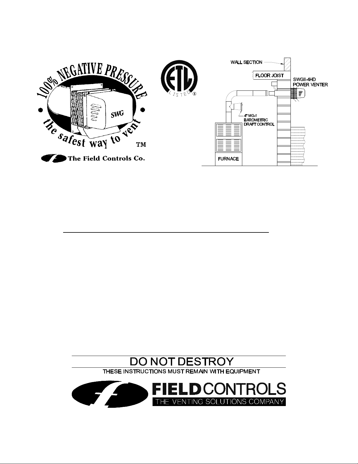
SWG SIDEWALL POWER VENTING KIT
Installation Specifications For The Following Furnaces
Certified As A Component Part of The Furnace Application.
This instruction sheet contains OEM specific information that supercedes the provided instruction
manual where applicable. All field wiring shown in included wiring diagrams are correct regardless
whether the CK-43 or CK-43F is used.
Contents
Kit P/N Furnace Manufacturer Page
46205411 Amana Refrigeration Inc. 2
46205405 American Standard Inc. & The Trane Co. 4
46205407 Armstrong Air Conditioning Inc. 6
46205410 Bard Manufacturing Co. 7
46205403 Carrier Corp. 8
46205408 Consolidated Industries Corp. 10
46205406 Dunkirk Radiator Corp. 11
Evcon Industries Inc. 13
46205401 International Comfort Products (Adjustable) 14
46205413 International Comfort Products (Fixed) 16
46205402 Lennox International Inc. 17
46205409 Rheem Air Conditioning 18
46205404 York International Corp. 19
Field Controls, L.L.C., 2630 Airport Road, Kinston, NC 28504
Technical Support (800) 742-8368
Page 2
SWG-4AM AMANA SIDEWALL POWER VENTING KIT
Field Controls P/N 46205411
Kit Includes:
SWGII-4HD Sidewall Power Venter
CK-43 Control Kit
Includes: 4" MG-1 Barometric Draft Control
Fan Proving Switch
Adjustable Post Purge
Recommended For Use On The Following Amana Model Furnaces:
GBI GCIC GUI GUID GCI GHI GUIA
GCIA GMI GUIB GCIB GSI GUIC
NOT For Use On The Following Amana Model Furnaces:
GCIS GUIS GUIV
Furnace Configuration and Vent Pipe Restrictions
Type B-1 vent pipe shall be used to join the furnace to the venting system and for the entire length of
the venting system. Exception: Up to 24" of single wall vent pipe may be used to connect the furnace
to the barometric damper. The barometric damper tee may be single wall. Type B-1/double wall vent
pipe MUST be used from the barometric damper tee to the power venter.
For Furnace Models GUIA, GUIB, GUIC, and GUID
BTU/Hr. Diameter of
Flue Collar
on Furnace
46,000 4" None 100 100
69,000 4" None 100 100
92,000 4" None 100 100
115,000 4" None 85 95
138,000 4" None 65 80
For Furnace Models GCIA, GCIB, and GCIC
BTU/Hr. Diameter of
Flue Collar
on Furnace
46,000 3" 3" to 4" 100 100
69,000 3" 3" to 4" 100 100
92,000 3" 3" to 4" 100 100
115,000 3" 3" to 4" 85 95
138,000 3" 3" to 4" 65 80
Installer
Provided Flue
Pipe Transition
Size Diameters
Installer
Provided Flue
Pipe Transition
Size Diameters
Maximum
Equivalent Length
(ft.) for 4" Vent Pipe
Maximum
Equivalent Length
(ft.) for 4" Vent Pipe
Maximum
Equivalent Length
(ft.) for 5" Vent Pipe
Maximum
Equivalent Length
(ft.) for 5" Vent Pipe
Page 2
Page 3
For Furnace Models GBI, GCI, GHI, GSI, and GUI
BTU/Hr. Diameter of
Flue Collar
on Furnace
45,000 3" 3" to 4" 100 100
70,000 3" 3" to 4" 100 100
90,000 3" 3" to 4" 100 100
115,000 4" None 85 95
140,000 4" None 65 80
For Furnace Models GMI
BTU/Hr. Diameter of
Flue Collar
on Furnace
40,000 3" 3" to 4" 100 100
60,000 4" None 100 100
80,000 4" None 100 100
100,000 4" None 100 100
120,000 4" None 80 90
140,000 4" None 60 80
Installer
Provided Flue
Pipe Transition
Size Diameters
Installer
Provided Flue
Pipe Transition
Size Diameters
Maximum
Equivalent Length
(ft.) for 4" Vent Pipe
Maximum
Equivalent Length
(ft.) for 4" Vent Pipe
Maximum
Equivalent Length
(ft.) for 5" Vent Pipe
Maximum
Equivalent Length
(ft.) for 5" Vent Pipe
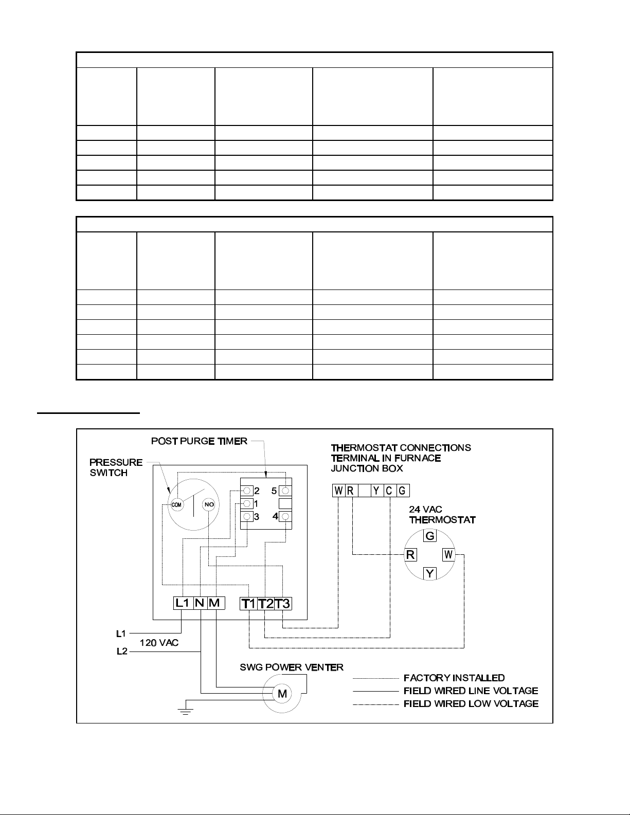
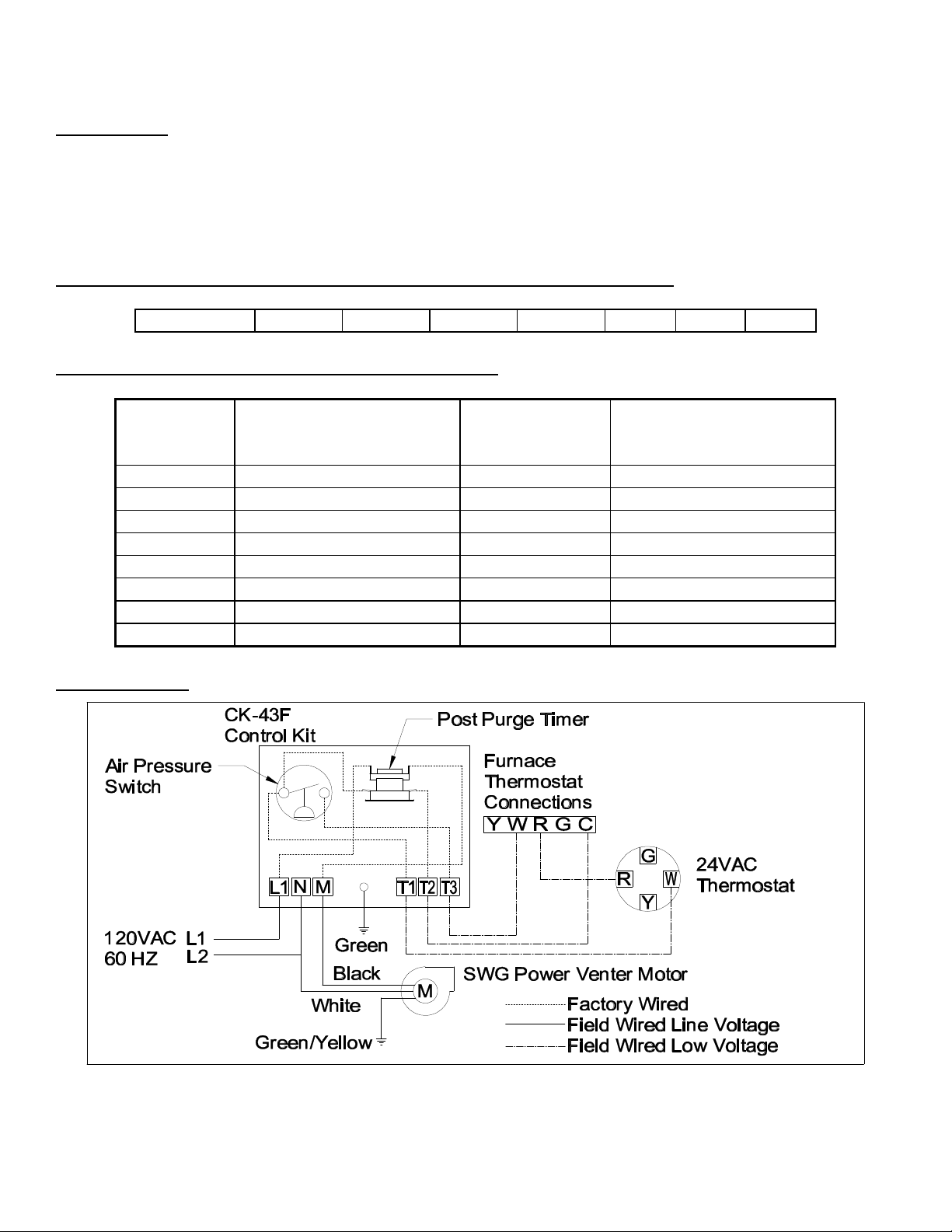
General Wiring
For complete installation information refer to the Field Controls SWG-4AM Power Venter Installation
Manual for details (P/N 46333300.)
Page 3
Page 4
SWG-4AT AMERICAN STANDARD AND TRANE
SIDEWALL POWER VENTING KIT
Field Controls P/N 46205405
Kit Includes:
SWGII-4HD Sidewall Power Venter
CK-43F Control Kit
Includes: 4" MG-1 Barometric Draft Control
Fan Proving Switch
Fixed post purge
For Use With The Following American Standard And Trane Furnaces:
AUD-C CUE-A ADD-R
TUD-C TUE-A TDD-R
AUD-R ADD-C CDE-A
TUD-R TDD-C TDE-A
Furnace Configuration And Vent Pipe Restrictions:
Furnace Input
BTU/Hr
40,000 4 65
60,000 4 65
80,000 4 65
100,000 4 65
120,000 4 65
140,000 4 65
General Wiring
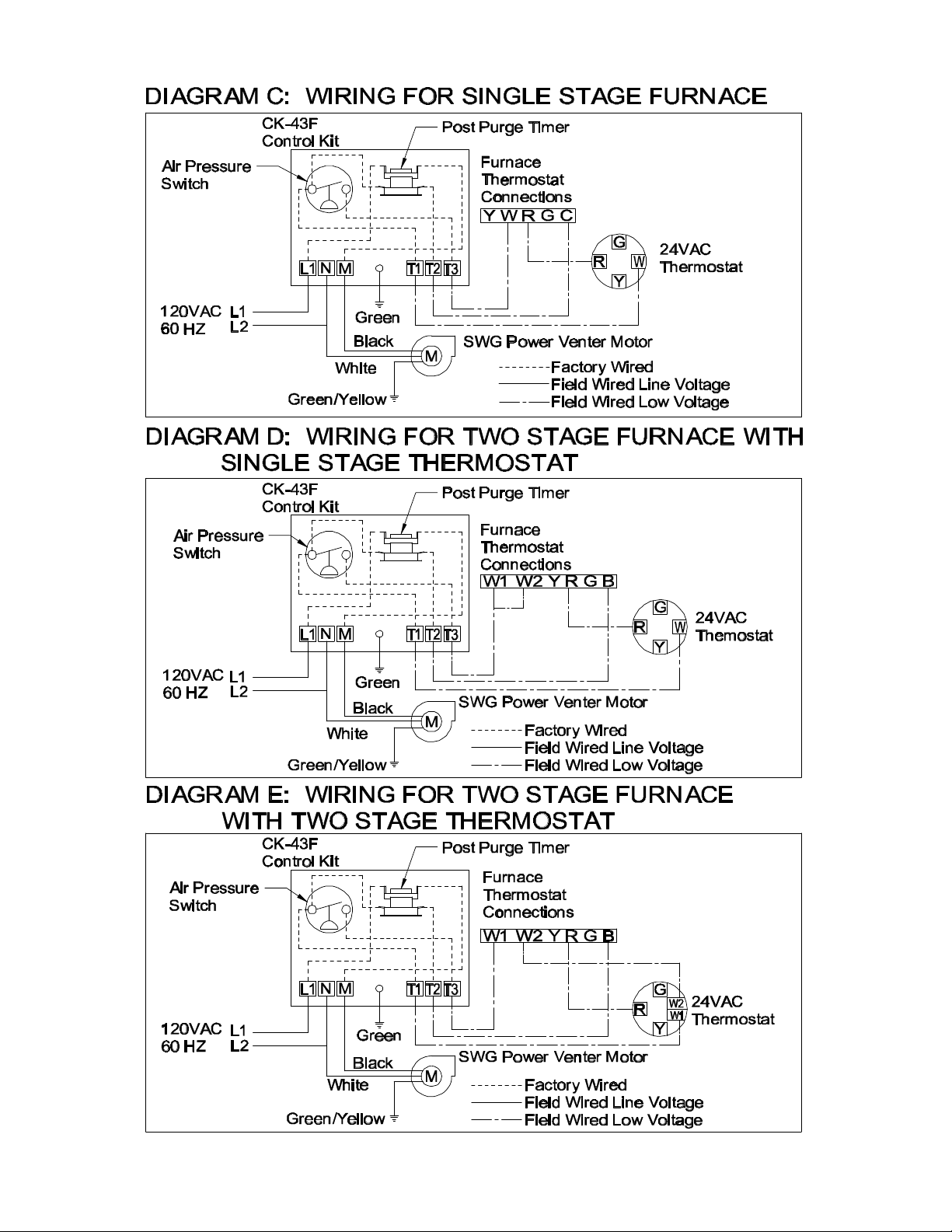
Refer to the Diagrams on the following page for guidance in wiring the Power Venter and Control Kit
to the appliance.
For complete installation information refer to the Field Controls SWG-4AT Power Venter Installation
Manual for details (P/N 46306700.)
Diameter Of Vent Pipe
Collar On Furnace (In.)
Maximum Equivalent
Vent Length (Ft.)
Page 4
Page 5
Page 5
Page 6
SWG-4A ARMSTRONG SIDEWALL POWER VENTING KIT
Field Controls P/N 46205407
Kit Includes:
SWGII-4HD Sidewall Power Venter
CK-43F Control Kit
Includes: 4" MG-1 Barometric Draft Control
Fan Proving Switch
Fixed post purge
For use with Armstrong furnace models that begin with the following:
AMEG6G EG5G EG6G EG7G EG8G GCJ GHJ GUJ
Furnace Configuration and Vent Pipe Restrictions
Model
Number
AMEG6G Upflow 4 60
EG5G Lowboy 4 60
EG6G Upflow 4 60
EG7G Downflow 4 60
EG8G Horizontal 4 41
GCJ Downflow-Horizontal 4 60
GHJ Upflow-Horizontal 4 60
GUJ Upflow 4 60
General Wiring
Configuration Furnace Vent
Collar Diameter
(in.)
Max. Equivalent Vent
Length (ft.); 4" Diameter
Vent Pipe
For complete installation information refer to the Field Controls SWG-4A Power Venter Installation
Manual for details (P/N 46333500.)
Page 6
Page 7

SWG-4B BARD SIDEWALL POWER VENTING KIT
Field Controls P/N 46205410
Kit Includes:
SWGII-4HD Sidewall Power Venter
CK-43F Control Kit
Includes: 4" MG-1 Barometric Draft Control
Fan Proving Switch
Fixed post purge
For Use With The Following Bard Standard Furnaces:
Upflow Downflow Lowboy
IH60D36 (A,B) IC60D36A ------
IH85D48 (A,B,D) IC85D42 (A,D) IL85D42 (A,D)
IH115D48 (A,B) IC115D48A IL115D48A
IH115D60A ------ -----IH145D60A ------ IL145D60A
Unit Selection Table:
Furnace Input
Btu/Hr
58,000 3” 3”-4” 65
86,000 4” ** 3”-4” *** 65
115,000 4” None Required 65
145,000 4” None Required 65
* Transition should be attached to the furnace vent pipe collar if required.
** 86,000 Btu models with A or B suffix letter have 3” collars.
*** 86,000 Btu models with D suffix have 4” collars and do not require a 3” to 4” transition.
General Wiring
For complete
installation
information refer to
the Field Controls
SWG-4B Power
Venter Installation
Manual for details
(P/N 46332100.)
Diameter Of Vent
Pipe Collar On
Furnace (In.)
Installer Provided Flue
Pipe Transition Size*
Maximum Equivalent
Vent Length (Ft.)
4” Vent Pipe
Page 7
Page 8

SWGII-4CC CARRIER SIDEWALL POWER VENTING KIT
Field Controls P/N 46205403, Carrier P/N KGASW03012SP
Kit Includes:
SWGII-4HD Sidewall Power Venter
CK-43CC Control Kit
Includes: 4" MG-1 Barometric Draft Control
Fan Proving Switch
Fixed post purge
For Use With The Following Carrier Furnace Models:
58UXT 58DXT 58UXV 58UHV 58TUA 58TMA
58WAV 58ZAV 58PAV 58RAV GB1AAV GB3AAV
For Use With The Following BDP Furnace Models:
330JAV 331JAV 333JAV 333BAV 330AAV 331AAV 395CAV
376CAV 383KAV 373LAV 480BAV 481BAV GB1AAV GB3AAV
For All Single-Furnace Systems:
Use one SWGII-4CC Kit for each furnace, and do not common-vent with other appliance(s). To
common-vent these furnaces with other appliances, use SWGII-4HD Kit with instruction P/N
46139100 and a CK Series Control Kit for each appliance.
For All Two-Stage furnaces:
When setting up a two-stage furnace, the furnace should be operating on HIGH-STAGE HEAT while
adjusting the sidewall power venter airflow adjustment damper, draft control, and proving switch.
VENTING INSTALLATION OPTIONS
FURNACE MODELS 4-in. dia. Type B-1 vent up
to 40 ft. long, up to 4
elbows, and 1 tee §
Two-Stage models
58UXT 330JAV
58DXT 331JAV
58UXV 333JAV
58UHV 333BAV
58TUA 330AAV
58TMA 331AAV
Single-Stage models
58WAV 395CAV
58ZAV 376CAV
58PAV 383KAV
58RAV 373LAV
GB1AAV 480BAV
GB3AAV 481BAV
PERMITTED WITH ALL
GAS INPUT SIZES
A 5"-to-4" reducer is
required between furnace
and vent for inputs greater
than 105,000 Btu/hr.
PERMITTED WITH ALL
GAS INPUT SIZES
A 5"-to-4" reducer is
required between furnace
and vent for inputs greater
than 115,000 Btu/hr.
3-in. dia. Type B-1 vent up to 40 ft.
long, up to 4 elbows, and 1 tee §
PERMITTED WITH ALL GAS
INPUT SIZES ‡
A reducer is required between
furnace and vent for these inputs:
up through 105,000 Btu/hr 4"-to-3"
more than 105,000 Btu/hr 5"-to-3".
PERMITTED WITH GAS INPUTS
OF 88,000 Btu/hr AND LESS ‡
A 4"-to-3" reducer is required
between furnace and vent.
Draft Safeguard
Switch Assembly
PERMITTED
WITH OR
WITHOUT THE
DRAFT
SAFEGUARD *
PERMITTED
ONLY WITH
THE DRAFT
SAFEGUARD †
Page 8
Page 9

* The furnace's Draft Safeguard switch assembly can remain in place as installed at the factory, or
the Draft Safeguard switch assembly can be removed (relief box opening sealed with Block-off
Plate and switch replaced with Splice Connector from Kit KGASW0101/02012SP).
† The Draft Safeguard switch assembly must remain installed and operational in the furnace.
§ See Equivalent Length Table II. Fewer elbows permit longer straight length & vice-versa.
‡ 3"-to-4" increaser is required between vent pipe and power venter.
General Wiring:
For complete installation information refer to the Field Controls SWGII-4CC Power Venter Installation
Manual for details (P/N 46295100.)
Page 9
Page 10

SWG-4CD CONSOLIDATED SIDEWALL POWER VENTING KIT
Field Controls P/N 46205408
Kit Includes:
SWGII-4HD Sidewall Power Venter
WMO-1 Thermal Safety Switch (Must be purchased separately if using other venting kit on
Consolidated Furnaces.)
CK-43F Control Kit
Includes: 4" MG-1 Barometric Draft Control
Fan Proving Switch
Fixed post purge
For use with the following series of furnaces:
This furnace was built by CONSOLIDATED
INDUSTRIES under the names: QUATRO, TECH-4,
QUADPRO, QUADTECH, MULTIFLOW, BRENTWOOD,
This furnace was built by
CONSOLIDATED INDUSTRIES
under the name PREMIER.
and SUNBURST.
Model Numbers: Model Numbers:
MAA040NR2R
MAA040NR3R
MAA060NR2R
MAA060NR3R
MAA060NR4R
MAA080NR2R
MAA080NR3R
MAA080NR4R
MAA080NR5R
MAA100NR3R
MAA100NR4R
MAA100NR5R
MAA120NR4R
MAA120NR5R
MAA140NR4R
MAA140NR5R
Note: Model numbers may have suffix "X". Note: Model numbers may have suffix "X".
This kit may also be used with furnaces manufactured by
Consolidated Industries and sold by a number of other companies
under their names.
MBA040NH2R
MBA040NH3R
MBA060NH2R
MBA060NH3R
MBA060NH4R
MBA080NH2R
MBA080NH3R
MBA080NH4R
MBA080NH5R
MBA100NH3R
MBA100NH4R
MBA100NH5R
MBA120NH4R
MBA120NH5R
MBA140NH4R
MBA140NH5R
MCA040NR2R
MCA040NR3R
MCA060NR2R
MCA060NR3R
MCA060NR4R
MCA080NR2R
MCA080NR3R
MCA080NR4R
MCA080NR5R
MCA100NR3R
MCA100NR4R
MCA100NR5R
MCA120NR4R
MCA120NR5R
MCA140NR4R
MCA140NR5R
MDA040NH2R
MDA040NH3R
MDA060NH2R
MDA060NH3R
MDA060NH4R
MDA080NH2R
MDA080NH3R
MDA080NH4R
MDA080NH5R
MDA100NH3R
MDA100NH4R
MDA100NH5R
MDA120NH4R
MDA120NH5R
MDA140NH4R
MDA140NH5R
HBA040NR3R
HBA060NR4R
HBA080NR4R
HBA100NR5R
HBA120NR5R
This kit may also be used with furnaces
manufactured by Consolidated Industries and
sold by a number of other companies under
their names.
General Information:
Page 10
Page 11

1. Maximum equivalent vent length is 63 feet for all furnaces listed!
2. The SWG-4CD power venter kit must be installed using type B-1 vent pipe only!
General Wiring
For complete installation information refer to the Field Controls SWG-4CD Power Venter Installation
Manual for details (P/N 46333600.)
SWG-4D DUNKIRK SIDEWALL POWER VENTING KIT
Field Controls P/N 46205406
Kit Includes:
SWGII-4HD Sidewall Power Venter
CK-43D Control Kit
Includes: 4" MG-1 Barometric Draft Control
Fan Proving Switch
Adjustable post purge
For use with the Dunkirk Radiator Boiler Models XEB 2-5 or Equivalent*
*To determine equivalent models, call (716)366-5500 and ask for Technical Service Department
Unit Sizing and Equivalent Footage
Max. Horizontal Vent Run Min. Horizontal Vent Run
50’+ Tee with a 3”x4” increaser for the
barometric draft control + 3”x4” increaser with
power venter
For additional elbows, reduce the maximum vent length as follows:
Page 11
2’+ 90° elbow + tee with a 3”x4” increaser for the
barometric draft control + 3”x4” increaser with
power venter
Page 12

3” x 90° elbow - reduce vent length by 3 feet for each elbow
Standard 3" single walled galvanized venting or 3" Type B vent pipe should be used.
Draft Control Installation:
1. Install a 3" vent pipe tee of the same material as the vent piping 12" to 24" away from the
outlet of the boiler's blower. Then place a 3"X4" reducer in the tee for mounting the barometric
draft control as shown in the Figure below.
2. Seal the vent pipe tee and reducer using the sealing and joining procedures in the boiler
installation instructions. Seal the barometric draft control into the tee using the same high
temperature silicone as used on the vent piping.
3. The front face of the control MUST be plumb and the bearing surfaces MUST be level whether
the control is on a horizontal, vertical, or sloping vent pipe. Use a spirit level and level
accurately. If necessary, the control may be held in place by sheet metal screws.
Dunkirk instructions continued on next page.
Page 12
Page 13

General Wiring
For complete installation information refer to the Field Controls SWG-4D,5D Power Venter
Installation Manual for details (P/N 46298400.)
SWG-4E EVCON SIDEWALL POWER VENTING KIT
Field Controls Standard Model SWGII-4HD and CK-43F
Kit Includes:
SWGII-4HD Sidewall Power Venter
CK-43F Control Kit
Includes: 4" MG-1 Barometric Draft Control
Fan Proving Switch
Fixed post purge
For Use On The Following Evcon Series of Furnace Models:
2800 AGU BGU
Page 13
Page 14

General Wiring:
For complete installation information refer to the Standard Field Controls SWG/SWGII series Power
Venter Installation Manual (P/N 46139100), and the CK-43F Control Kit Installation Manual (P/N
46285100) for details.
SWG-4IC INTER-CITY SIDEWALL POWER VENTING KIT
Field Controls P/N 46205401
Kit Includes:
SWGII-4HD Sidewall Power Venter
CK-43 Control Kit
Includes: 4" MG-1 Barometric Draft Control
Fan Proving Switch
Adjustable Post purge
For Use With The Following Furnace Models:
GDJ GDL GNI GNJ GNL CUGE CUG5
NCC5 NDC7 NDN5 NTC5 NTC7 NTN5 NUG5
Page 14
Page 15

Unit Sizing:
BTU/HR Input Diameter Of Vent Pipe To
Power Venter
50,000 3” 3” TO 4”
75,000 4” None Required
100,000 4” None Required
125,000 4” None Required
Maximum Pipe Length - (3) 90° Elbows, 30 feet of vent pipe and reducer or increaser if required.
Minimum Pipe Length - (1) 90° Elbow, 5 feet of vent pipe and a reducer or increaser if required.
General Wiring
Flue Pipe Transition Size
Diameter
For complete installation information refer to the Field Controls SWG-4IC Power Venter Installation
Manual for details (P/N 46201400.)
Page 15
Page 16

SWG-4ICF INTER-CITY SIDEWALL POWER VENTING KIT
Field Controls P/N 46205413
Kit Includes:
SWGII-4HD Sidewall Power Venter
CK-43F Control Kit
Includes: 4" MG-1 Barometric Draft Control
Fan Proving Switch
Fixed post purge
For Use With The Following Series Of Furnaces
GDJ GDL GNI GNJ GNL CUGE CUG5
NCC5 NDC7 NDN5 NTC5 NTC7 NTN5 NUG5
Unit Selection Table
BTU/HR
Input
50,000 3" 3" TO 4"
Diameter Of Vent Pipe To
Power Venter
Flue Pipe Transition Size
Diameter
General Wiring
75,000 4" None Required
100,000 4" None Required
125,000 4" None Required
For complete installation information refer to the Field Controls SWG-4ICF Power Venter Installation
Manual for details (P/N 46319700.)
Page 16
Page 17

SWG-4L LENNOX SIDEWALL POWER VENTING KIT
Field Controls P/N 46205402
Kit Includes:
SWGII-4HD Sidewall Power Venter
CK-43 Control Kit
Includes: 4" MG-1 Barometric Draft Control
Fan Proving Switch
Adjustable post purge
For Use On The Following Lennox Series Furnaces:
G23 G24M 80MGF
Unit Selection And Maximum Vent Length Table
BTU/Hr Input Diameter Of
Vent Pipe Collar
On Furnace
45,000* 3" 3" to 4" 60 60
50,000 3" 3" to 4" 60 60
60,000* 3" 3" to 4" 60 60
75,000* 4" None Required 60 60
100,000* 4" None Required 60 60
120,000* 4" None Required 60 60
125,000 5" 4" to 5" 60 60
140,000* 4" None Required 48 60
150,000 5" 4" to 5" 35 60
*G24M/80MGF Input Rates
General Wiring:
For complete installation
information refer to the
Field Controls SWG-4L
Power Venter Installation
Manual for details (P/N
46257600.)
Installer Provided
Flue Pipe Transition
Size Diameters
Maximum
Equivalent Length
(Ft) For 4" Vent Pipe
Maximum
Equivalent Length
(Ft) For 5" Vent Pipe
Page 17
Page 18

SWG-4R RHEEM SIDEWALL POWER VENTING KIT
Field Controls P/N 46205409
Kit Includes:
SWGII-4HD Sidewall Power Venter
CK-43R Control Kit
Includes: 4" MG-1 Barometric Draft Control
Fan Proving Switch
Fixed post purge
For Use With The Following Rheem, Ruud, And Weatherking Model Series Furnaces:
(-)GDG* (-)GDJ* (-)GVH* (-)GPH* (-)GLG (-)GLH* (-)GVG (-)GLJ*
(-)GPJ* (-)GVJ* (-)GDC (-)GLC (-)GDE (-)GLE (-)GVC (-)GYC
(-)GVA (-)GYA (-)GVB (-)GYB WGVAH WGVAG WGDAG WGLAG
*Indicated models are CGA certified with the SWG-4R as a vent system.
Indicated 45,000 and 67,500 BTU furnaces must not be auxiliary power vented unless the original
vent pressure switch is replace with a 0.30 vent pressure switch, Rheem P/N 42-24064-01. Failure to
replace the pressure switch as specified could lead to improper operation of the furnace resulting in
property damage, personal injury, or death.
Application & Installation Notes:
1. READ THE POWER VENTER APPLICATION & INSTALLATION INSTRUCTIONS VERY
CAREFULLY BEFORE ATTEMPTING TO INSTALL AND/OR OPERATE THE POWER
VENTER.
2. Do not use this kit with HTPV or SVS vent pipe. Use only “B” type vent pipe.
3. Do not exceed 30 linear feet of type “B” vent pipe or maximum of three 90° elbows.
4. Carefully observe the minimum required % combustion efficiency and the maximum
measure flue gas temperature.
5. Each furnace must have a dedicated power venter. Common venting with more than one
appliance to a power venter is not permitted.
6. Note: Where a 3” to 4” and 4” to 6” vent pipe transitions are necessary, use only tapered
transitions.
7. The barometric draft control is supplied with the power venting kit. (It is required, but not
supplied with the Tjernlund kit.) Regardless of vent pipe diameter size, a 4” diameter gas
furnace barometric draft control is required to be installed with in three (3) feet of the
furnace cabinet.
8. Do not attempt to use this power venter on a furnace equipped with a draft hood or a vent
damper.
9. Carefully observe ambient air temperature limitations.
Important: Under no circumstances can any standing pilot furnace be horizontally vented.
Under no circumstances can any additional appliances be common vented with the
furnace by the Field Controls SWG-4R.
Under no circumstances can a furnace equipped with a natural draft diverter be
horizontally vented.
Page 18
Page 19

Vent Specifications:
1. All vent pipe and elbows must be Type B, double wall vent.
2. The maximum vent length is 30 feet with a maximum of three 90° elbows.
3. The minimum vent length is 5 feet.
4. Use 3" vents for models with inputs through 75,000 BTU/Hr.
5. Use 4" vents for models with inputs over 75,000 BTU/Hr.
6. A 4" barometric damper is included in the power venter kit. When 3" vent pipe is used, a 3" to
4" single wall increaser is required for connecting the barometric damper and for connecting
the power venter. A single wall increaser will also be required at the furnaces with 3" outlet
collars when 4" vent pipe is used.
General Wiring
For complete installation information refer to the Field Controls SWG-4R Power Venter Installation
Manual for details (P/N 46331300.)
SWG-4Y YORK SIDEWALL POWER VENTING KIT
Field Controls Part #46205404
Kit Includes:
SWGII-4HD Sidewall Power Venter
CK-43F Control Kit
Includes: 4" MG-1 Barometric Draft Control
Fan Proving Switch
Fixed post purge
Approved For Use On The Following York International Model Furnaces:
Page 19
Page 20

P1UK P2MP P9MP P2DP P3UC P9UC P3CC P9CC PKMD
PAKU PBKM XEM PBKD XED PCMU PKMU PCMD
Unit Sizing And Equivalent Footage
Refer to the following to choose the proper size vent pipe and fittings for connecting the SWG power
venter to the appliance. The following table also lists the maximum equivalent length of vent pipe
allowed, depending on the appliance input rating and the diameter of vent pipe used.
BTU/Hr
Input
Diameter Of Vent
Pipe Collar On
Furnace
Installer Provided
Flue Pipe Transition
Size Diameters
Maximum
Equivalent
Length (Feet)
40,000 3" 3" TO 4" 100
60,000 3" 3" TO 4" 100
80,000 4" None Required 100
100,000 4" None Required 100
120,000 4" None Required 80
140,000 4" None Required 65
General Wiring
4" Vent Pipe
For complete installation information refer to the Field Controls SWG-4Y Power Venter installation
manual for details (P/N 46297600.)
P/N 46334200
Page 20
 Loading...