

Page 1
Installation Guide
Hardware Platform 10
FChwp10
Page 2

Page 3

Safety Information
The following are warnings or safety guidelines. A warning means danger. You are in a
situation that could cause bodily injury. Before you work on any equipment, be aware of
the hazards involved with electrical circuitry and be familiar with standard practices for
preventing accidents.
Qualified Personnel Warning
Only trained and qualified personnel should install or replace the device.
Waarschuwing Installatie en reparaties mogen uitsluitend door getraind en bevoegd personeel uitgevoerd
Varoitus Ainoastaan koulutettu ja pätevä henkilökunta saa asentaa tai vaihtaa tämän laitteen.
worden.
Avertissement L'installation ou le remplacement de cet appareil doit être réalisé par du personel qualifié et
Achtung Gerät nur von geschultem, qualifiziertem Personal installieren oder auswechseln lassen.
Avvertenza Solo personale addestrato e qualificato deve essere autorizzato ad installare o sostituire
Advarsel Kun kvalifisert personell med riktig opplæring bør montere eller bytte ut dette utstyret.
Aviso Este equipamento deverá ser instalado ou substituído apenas por pessoal devidamente
¡¡Atencióón! Estos equipos deben ser instalados y reemplazados exclusivamente por personal téécnico
Varning! Denna utrustning ska endast installeras och bytas ut av utbildad och kvalificerad personal.
compétent.
questo apparecchio.
treinado e qualificado.
adecuadamente preparado y capacitado.
Installation Warning
Read the installation instructions before you connect the device to a power source.
Waarschuwing Raadpleeg de installatie-aanwijzingen voordat u het systeem met de voeding verbindt.
Varoitus Lue asennusohjeet ennen järjestelmän yhdistämistä virtalähteeseen.
Attention Avant d'alimenter cet appareil, veuillez consulter le manuel d'installation.
Warnung Lesen Sie die Installationsanweisungen, bevor Sie das System an die Stromquelle
anschließen.
Avvertenza Consultare le istruzioni di installazione prima di collegare il sistema all'alimentatore.
Advarsel Les installasjonsinstruksjonene før systemet kobles til strømkilden.
Aviso Leia as instruções de instalação antes de ligar o sistema à sua fonte de energia.
¡¡Atencióón! Ver las instrucciones de instalación antes de conectar el sistema a la red de alimentación.
Varning! Läs installationsanvisningarna innan du kopplar systemet till dess strömförsörjningsenhet.
Page 4

Restricted Access Area Warning
The device is intended for installation in restricted access areas. A restricted access area is an area
to which access can be gained only by service personnel through the use of a special tool, lock and
key, or other means of security, and that is controlled by the authority responsible for the location.
Waarschuwing Dit toestel is bedoeld voor installatie op plaatsen met beperkte toegang. Een plaats met
Varoitus Tämä laite on tarkoitettu asennettavaksi paikkaan, johon pääsy on rajoitettua. Paikka, johon
Attention Cet appareil est à installer dans des zones d'accès réservées où seul le personel de service
Warnung Diese Einheit ist zur Installation in Bereichen mit beschränktem Zutritt vorgesehen. Ein
Avvertenza Questa unità deve essere installata in un'area ad accesso limitato. Un'area ad accesso
Advarsel Denne enheten er laget for installasjon i områder med begrenset adgang. Et område med
Aviso Esta unidade foi concebida para instalação em áreas de acesso restrito. Uma área de acesso
beperkte toegang is een plaats waar toegang slechts door servicepersoneel verkregen kan
worden door middel van een speciaal instrument, een slot en sleutel, of een ander
veiligheidsmiddel, en welke beheerd wordt door de overheidsinstantie die verantwoordelijk is
voor de locatie.
pääsy on rajoitettua, tarkoittaa paikkaa, johon vain huoltohenkilöstö pääsee jonkin
erikoistyökalun, lukkoon sopivan avaimen tai jonkin muun turvalaitteen avulla ja joka on
paikasta vastuussa olevien toimivaltaisten henkilöiden valvoma.
peut y accéder soit en déverrouillant un cadenas soit en désactivant un autre moyen de
sécurité. L'accès aux zones de sécurité est sous la responsabilité de l'établissement.
Bereich mit beschränktem Zutritt ist ein Bereich, zu dem nur Wartungspersonal mit einem
Spezialwerkzeugs, Schloß und Schlüüssel oder anderer Sicherheitsvorkehrungen Zugang hat,
und der von dem füür die Anlage zuständigen Gremium kontrolliert wird.
limitato è un'area accessibile solo a personale di assistenza tramite un'attrezzo speciale,
lucchetto, o altri dispositivi di sicurezza, ed è controllata dall'autorità responsabile della zona.
begrenset adgang gir kun adgang til servicepersonale som bruker et spesielt verktøy, lås og
nøkkel, eller en annen sikkerhetsanordning, og det kontrolleres av den autoriteten som er
ansvarlig for området.
restrito é uma área à qual apenas tem acesso o pessoal de serviço autorizado, que possua
uma ferramenta, chave e fechadura especial, ou qualquer outra forma de segurança. Esta
área é controlada pela autoridade responsável pelo local.
Advertencia! Esta unidad ha sido diseñada para instalarse en áreas de acceso restringido. Área de acceso
Varning! Denna enhet är avsedd för installation i områden med begränsat tillträde. Ett område med
restringido significa un área a la que solamente tiene acceso el personal de servicio mediante
la utilización de una herramienta especial, cerradura con llave, o algún otro medio de
seguridad, y que está bajo el control de la autoridad responsable del local.
begränsat tillträde får endast tillträdas av servicepersonal med ett speciellt verktyg, lås och
nyckel, eller annan säkerhetsanordning, och kontrolleras av den auktoritet som ansvarar för
området.
Disclaimer
The information in this manual has been carefully checked and is believed to be accurate.
CER assumes no responsibility for any infringements or patents or other rights of third
parties that may result from its use. CER assumes no responsibility for any inaccuracies
that may be contained in this document. CER makes no commitment to update or keep
current the information in this manual. CER reserves the right to make improvements to
this document and/or products at any time and without notice.
Software License Terms (End User License Agreement)
This device contains software. The software is licensed !
Read the software licensen terms and check the User’s Guide for detailed info.
Page 5

Power Supply Disconnection Warning
Before working on the device or near power supplies, disconnect the power.
Waarschuwing Voordat u aan een frame of in de nabijheid van voedingen werkt, dient u bij wisselstroom
Varoitus Kytke irti vaihtovirtalaitteiden virtajohto ja katkaise tasavirtalaitteiden virta suojakytkimellä,
Attention Avant de travailler sur cet appareil, veuillez couper les alimentations à courant alternatif et
Warnung Bevor Sie an einem Chassis oder in der Nähe von Netzgeräten arbeiten, ziehen Sie bei
Avvertenza Prima di lavorare su un telaio o intorno ad alimentatori, scollegare il cavo di alimentazione
Advarsel Før det utføres arbeid på kabinettet eller det arbeides i nærheten av str¿mforsyningsenheter,
Aviso Antes de trabalhar num chassis, ou antes de trabalhar perto de unidades de fornecimento de
¡¡Advertencia! Antes de manipular el chasis de un equipo o trabajar cerca de una fuente de alimentación,
Varning! Innan du arbetar med ett chassi eller nära strömförsörjningsenheter skall du för
toestellen de stekker van het netsnoer uit het stopcontact te halen; voor gelijkstroom
toestellen dient u de stroom uit te schakelen bij de stroomverbreker.
ennen kuin teet mitään asennuspohjalle tai työskentelet virtalähteiden läheisyydessä.
continu de celui-ci.
Wechselstromeinheiten das Netzkabel ab bzw. schalten Sie bei Gleichstromeinheiten den
Strom am Unterbrecher ab.
sulle unità CA; scollegare l'alimentazione all'interruttore automatico sulle unità CC.
skal str¿mledningen trekkes ut p vekselstrømsenheter og strømmen kobles fra ved
strømbryteren på likestrømsenheter.
energia, desligue o cabo de alimentação nas unidades de corrente alternada; desligue a
corrente no disjuntor nas unidades de corrente contínua.
desenchufar el cable de alimentación en los equipos de corriente alterna (CA); cortar la
alimentación desde el interruptor automático en los equipos de corriente continua (CC).
växelströmsenheter dra ur nätsladden och för likströmsenheter bryta strömmen vid
överspänningsskyddet.
Device handling
Anti-Static handling
The device contains CMOS devices that could be damaged in the venet of static electricity
discharged through them. At all times use anti static precautions when handling the
device.
Battery
This device contains a non-rechargebale battery. Do not short-cut the battery.
Please ensure that if the battery is replaced that the new part conforms to the same
specifications.
Electromagnetic Compatibility (EMC)
The EWS1700 is classified as a component with regards to the European Community EMC
regulations and it is the users responsibility to ensure that systems using this device are
compliant with the appropiate EMC standards.
Packaging
Please ensure that if a device should be returned to CER, it is adequately packed,
preferable in the original packing material.
Page 6

Hardware Platform 10 Installation Guide
Table of Contents
Safety Information . . . . . . . . . . . . . . . . . . . . . . . . . . . . . . . . . . . . . . . . . . . . . . . . 3
Qualified Personnel Warning . . . . . . . . . . . . . . . . . . . . . . . . . . . . . . . . . . . . . . 3
Installation Warning . . . . . . . . . . . . . . . . . . . . . . . . . . . . . . . . . . . . . . . . . . . . . 3
Restricted Access Area Warning . . . . . . . . . . . . . . . . . . . . . . . . . . . . . . . . . . . . 4
About this manual . . . . . . . . . . . . . . . . . . . . . . . . . . . . . . . . . . . . . . . . . . . . . . . . 7
Installation . . . . . . . . . . . . . . . . . . . . . . . . . . . . . . . . . . . . . . . . . . . . . . . . . . . . . . 8
System requirements . . . . . . . . . . . . . . . . . . . . . . . . . . . . . . . . . . . . . . . . . . . . 8
Getting familiar . . . . . . . . . . . . . . . . . . . . . . . . . . . . . . . . . . . . . . . . . . . . . . . . 8
Front . . . . . . . . . . . . . . . . . . . . . . . . . . . . . . . . . . . . . . . . . . . . . . . . 8
Back . . . . . . . . . . . . . . . . . . . . . . . . . . . . . . . . . . . . . . . . . . . . . . . . 9
Bottom . . . . . . . . . . . . . . . . . . . . . . . . . . . . . . . . . . . . . . . . . . . . . . 10
Hardware installation . . . . . . . . . . . . . . . . . . . . . . . . . . . . . . . . . . . . . . . . . . . 11
Physical installation . . . . . . . . . . . . . . . . . . . . . . . . . . . . . . . . . . . . . 11
Connecting power . . . . . . . . . . . . . . . . . . . . . . . . . . . . . . . . . . . . . . 11
Connecting to the network . . . . . . . . . . . . . . . . . . . . . . . . . . . . . . . . 13
IP configuration . . . . . . . . . . . . . . . . . . . . . . . . . . . . . . . . . . . . . . . . . . . . . . . . . 15
Addressing basics . . . . . . . . . . . . . . . . . . . . . . . . . . . . . . . . . . . . . . . . . . . . . 15
Assigning an IP address on a FieldCommander . . . . . . . . . . . . . . . . . . . . . . . . . 16
Configure IP address with browser . . . . . . . . . . . . . . . . . . . . . . . . . . 16
Force new IP address using ARP+PING . . . . . . . . . . . . . . . . . . . . . . . 19
Assigning an IP address on an ELS controller . . . . . . . . . . . . . . . . . . . . . . . . . . 20
Assigning an IP address on an EWS controller . . . . . . . . . . . . . . . . . . . . . . . . . . 21
Testing the Ethernet connection . . . . . . . . . . . . . . . . . . . . . . . . . . . . . . . . . . . 22
The ping test . . . . . . . . . . . . . . . . . . . . . . . . . . . . . . . . . . . . . . . . . . 22
The browser test . . . . . . . . . . . . . . . . . . . . . . . . . . . . . . . . . . . . . . . 22
Serial interface . . . . . . . . . . . . . . . . . . . . . . . . . . . . . . . . . . . . . . . . . . . . . . . . . . 23
RS-232 . . . . . . . . . . . . . . . . . . . . . . . . . . . . . . . . . . . . . . . . . . . . . . . . . . . . . 23
The RS-232c standard . . . . . . . . . . . . . . . . . . . . . . . . . . . . . . . . . . . 23
The connections . . . . . . . . . . . . . . . . . . . . . . . . . . . . . . . . . . . . . . . 23
The RS-232c pin-out . . . . . . . . . . . . . . . . . . . . . . . . . . . . . . . . . . . . 23
RS-485 (option only) . . . . . . . . . . . . . . . . . . . . . . . . . . . . . . . . . . . . . . . . . . . 24
The RS-485 standard . . . . . . . . . . . . . . . . . . . . . . . . . . . . . . . . . . . . 24
The connections . . . . . . . . . . . . . . . . . . . . . . . . . . . . . . . . . . . . . . . 24
The RS-485 pin-out . . . . . . . . . . . . . . . . . . . . . . . . . . . . . . . . . . . . . 26
Ports on your controller . . . . . . . . . . . . . . . . . . . . . . . . . . . . . . . . . . . . . . . . . 27
Pin Assignments . . . . . . . . . . . . . . . . . . . . . . . . . . . . . . . . . . . . . . . . . . . . . . . . . 28
Technical Specifications . . . . . . . . . . . . . . . . . . . . . . . . . . . . . . . . . . . . . . . . . . . 31
Physical Dimensions . . . . . . . . . . . . . . . . . . . . . . . . . . . . . . . . . . . . . . . . . . . . . . 33
Notice to the user . . . . . . . . . . . . . . . . . . . . . . . . . . . . . . . . . . . . . . . . . . . . . . . . 34
Regulatory . . . . . . . . . . . . . . . . . . . . . . . . . . . . . . . . . . . . . . . . . . . . . . . . . . 34
Trademarks . . . . . . . . . . . . . . . . . . . . . . . . . . . . . . . . . . . . . . . . . . . . . . . . . . 35
Copyrights . . . . . . . . . . . . . . . . . . . . . . . . . . . . . . . . . . . . . . . . . . . . . . . . . . 35
6
Page 7
About this manual
About this manual
This document is intended for users of the FieldCommander, ELS- or EWS controllers that
are based on the HWP10-platform and explains the steps to install and setup the system
in your environment.
This guide contains information to install and configure the unit in your networking
environment, as well as a basic overview of the serial communication hardware and IPaddressing. It provides all knowledge needed to connect the device in a way that the CER
controller is accessible and ready for further use.
Organisation of the documentation
Installation Installation Guide Hardware Platform 10 (FCHWP10IG)
Bundles information related to the hardware, such as the installation of the
device, IP networking, serial interface details and technical specifications.
For ELS controllers:
Employment Software User's Guide (ELSSWUG)
Explains the configuration of the ELS controller
.
For EWS controllers:
Employment Software User's Guide (EWSSWUG)
Explains the configuration of the EWS controller
For FieldCommander controllers:
Employment Software User's Guide (FCSWUG)
Explains how FieldCommander is used in your application development, and
documents all its features, including the configuration
Programming FCscript Programmer's Guide (FCSCRPG)
Function reference of FieldCommander's scripting language, used to create
control applications.
FCphp Programmer's Guide (FCPHPPG)
Function descriptions of the FieldCommander specific PHP interface, used to
build dynamic user interfaces on top of the control application.
Software options Modbus Software Option (FCOPT010)
Galaxy Software Option ( FCOPT020)
The "option" modules have their own documentation to explain the
features, installation, configuration and programming interfaces.
References Javascript Reference Manual (FCJSREF)
Extensive documentation of the Javascript (ECMAscript) core language used
by FieldCommander for application programming.
.
.
PHP Language Manual
Complete documentation of the PHP language and functions.
CER International bv 7
Page 8
Hardware Platform 10 Installation Guide
Installation
This chapter explains the installation in detail and along the way it introduces you to
some of the concepts important to understand the operation of your controller unit.
System requirements
In order to connect to the controller, you need a valid TCP/IP network connection and a
browser. To be complete, it requires:
• 10Mbit (10base-T) or 100Mbit (100base-T) network connection with RJ-45 socket
• operating system with TCP/IP protocol stack
• Internet browser
CER International releases firmware updates regularly with enhancements, changes and
fixes. Updates may feature new functionality, so it is a good idea to occasionally check
the website at http://www.cer.com for new firmware releases.
Getting familiar
In this chapter we describe the connectors of your controller. Depending on the product
model all controls are located on the front of the unit, or controls are on both sides:
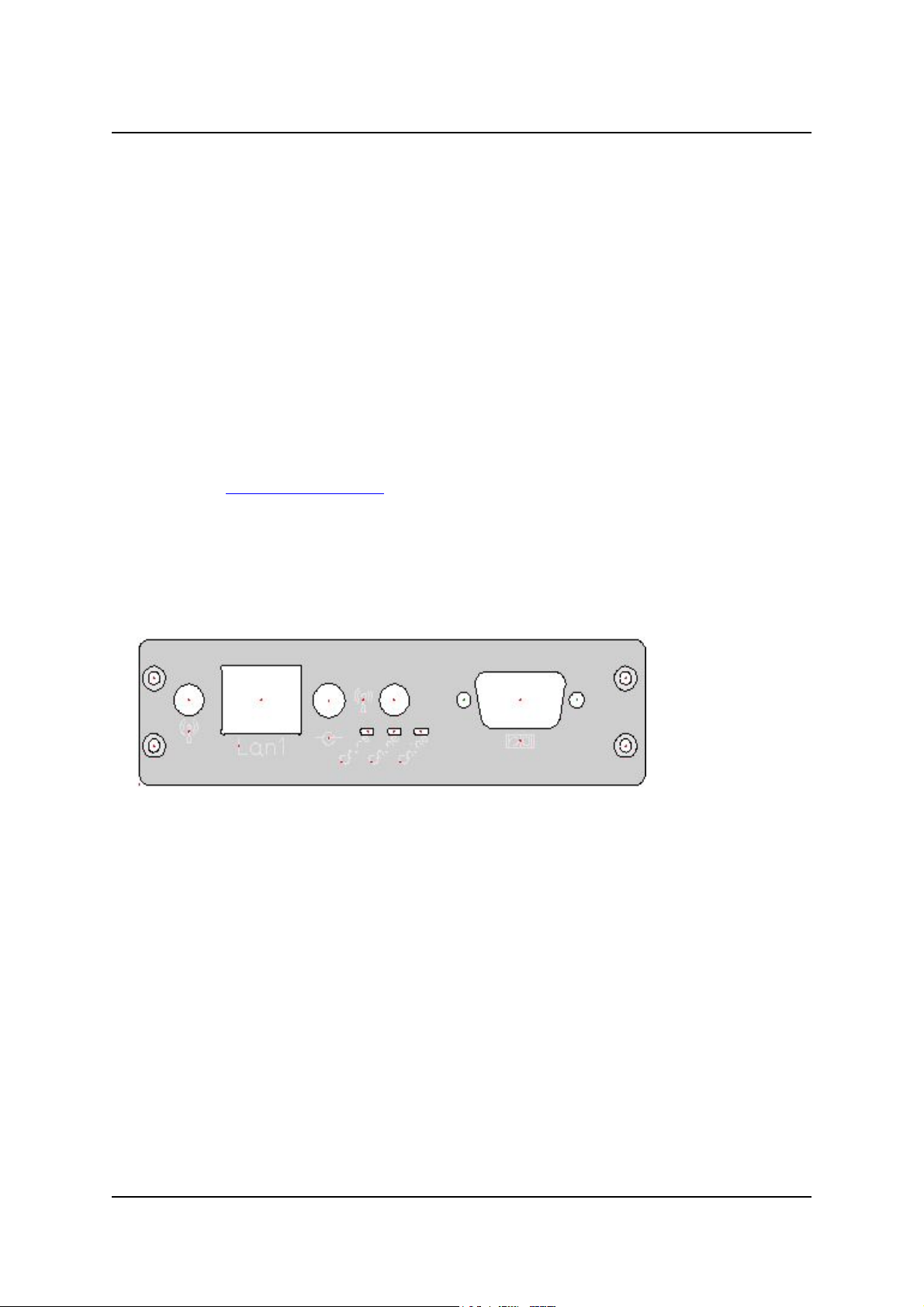
Front
Ethernet Power RS232
Serial port
The 9-pin port is used to connect your controller to your serial equipment. The chapter
called "Serial Interface" uncovers the details of serial communication and pin-out of the
connector.
Ethernet connector
The CER controller is equipped with an Ethernet LAN controller that is fully compliant with
IEEE 802.3 10/100Base-T CSMA/CD standards. The Ethernet port provides a standard
RJ-45 jack on board. After completion of the startup process, two LED indicators provide
information about the status of the network connection. The Green LED (right) indicates
that there is a physical connection (link) to the network. The Green LED (left) indicates
network activity. It flashes when there is any data on the line; it's not necessarily
addressed to the controller.
This connector implements a passive power over Ethernet scheme, using the two unused
pairs. More about this can be found in the section ‘Power over Ethernet’ in the next
chapter.
8
Page 9
Installation
LED indicator
Next to the Power Connector there is a green LED on the front panel for indicating system
status. This LED is lit when power is supplied to the unit.
Power connector
Power to the controller is accommodated by a DC jack “J9” or by passive power over
ethernet connector. The DC jack is attached to a 18V external DC power supply. Power
supplied to the unit must be within the specifications listed in this manual.
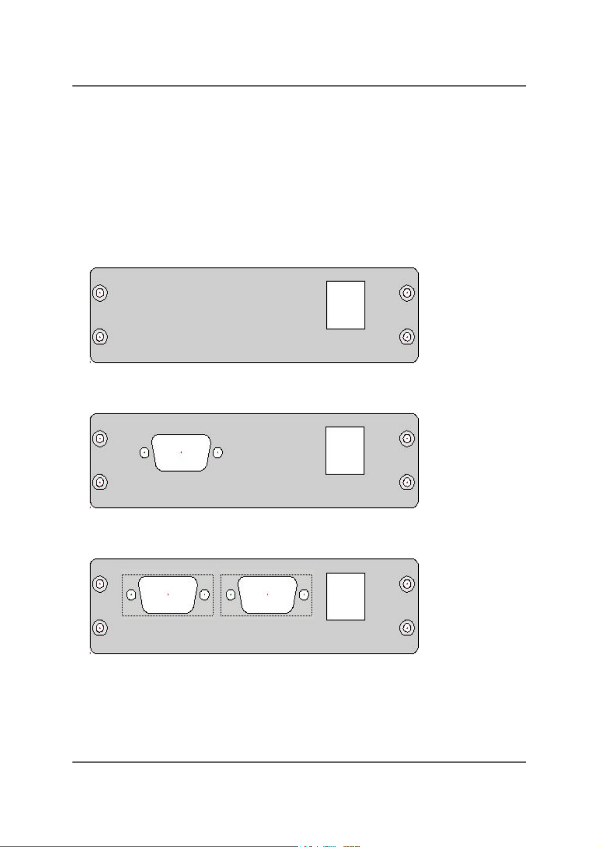
Back
(FC2700/FC3700 only)
USB
(FC372x only)
RS232/RS485 USB
(FC373x only)
RS232/RS485 RS232 USB
CER International bv 9
Page 10
Hardware Platform 10 Installation Guide
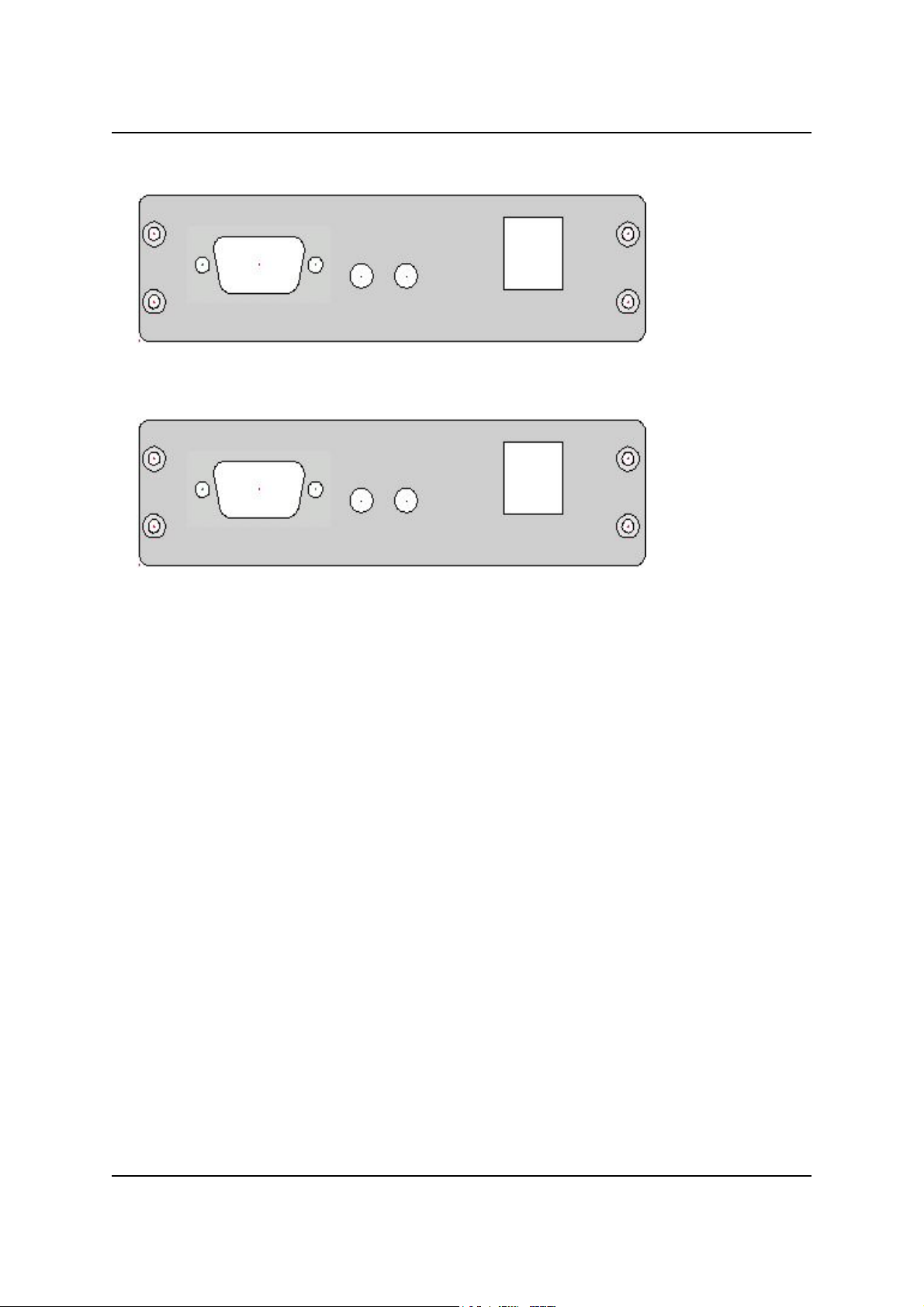
(ELS1700 or EWS1700 only)
VGA Audio USB
(ELS172x only) To be defined !!
VGA Audio USB
Serial port
The 9-pin port is used to connect your controller to your serial equipment. The chapter
called "Serial Interface" uncovers the details of serial communication and pin-out of the
connector.
USB connectors
The back panel features two USB connectors.
Bottom
Serial Number
The affixed label on the back of the unit states the products serial number which is
identical to its MAC address.
10
Page 11

Installation
Hardware installation
You communicate with the controller over the Ethernet network. In this part of the
chapter, you'll learn about the unit itself and how and where to connect it. There are no
configurable parts inside. Everything is controlled and configured by the software.
Physical installation
You can use the controller in several places, depending on your needs:
• freely (unfixed) on your desktop with the included adhesive plastic bumpers.
• fixed to a DIN-rail using the supplied DIN-rail clips. These can be inserted into the
holes in the case. Be sure to position the rebated joints at the outside of the
Controller for easy removal of the case from the DIN-rail in the future.
• if outdoor option: fixed to a wall or 1" mast using the waterproof NEMA-67 outdoor
case
Connecting power
The controller requires power of a single 7-18VDC. The power consumption is rated at
12VDC/0.25A
Over Ethernet.
and 12VDC/0.4A
TYP
. This can be applied using a Power adaptor or Power
MAX
Power adaptor
Warning! Always disconnect the power cord from the controller when you
are (dis)mounting devices, interfaces or sensors. Do not (dis)connect
while the power is on. A sudden rush of power can damage sensitive
electronic components.
Follow these steps to connect the controller to your power supply:
1. Make sure the power supply is unplugged
2. Connect the DC jack to your controller
Now you can safely plug in your power supply. Notice that the PWR indicator lights up.
Warning! The controller has very low ESR input capacitors.
To avoid arcing, please plug in the DC jack to the controller first, then
plug the AC adapter into mains.
CER International bv 11
Page 12

Hardware Platform 10 Installation Guide
Power Over Ethernet
In your controller a passive power over Ethernet (PoE) scheme is implemented (see
below), using the unused pairs of the LAN port for power.
Power can be injected using passive POE splitter which can be ordered seperately.
POE Splitter FieldCommander
LAN
POE
Power
12
Page 13

Installation
Connecting to the network
Before connecting the controller to the network, you might want to consult your network
administrator. You can employ the controller at various points in your ethernet network
as shown below.
Make sure the IP addressing scheme of your controller does not interfere with your
existing network configuration. The chapter "IP configuration" takes the myths out of it.
Three ways to connect your controller to Ethernet:
Local LAN
Remote WAN
Point-to-Point
LAN
gateway/
router
Internet
Local LAN: The controller is part of the local Ethernet network by connecting it
to the hub or switch using a straight cable, just like your own
workstation.
Remote WAN: When you co-locate the controller, you can connect to it through a
public network like the Internet. In this case, the controller is
connected to the network through your Internet gateway/router
with Port Forwarding support using the supplied straight cable. The
gateway/router establishes the connection between your ISP and
the controller.
Point-to-Point: You can connect the controller to your workstation directly using a
crossed ethernet cable (not supplied). Use this setup where you
don't have a Ethernet LAN available or when you don't want to use
it for the controller.
Decide first where you want to connect the CER controller as it affects some of the steps
in the installation, most importantly cabling requirements and IP configuration.
CER International bv 13
Page 14

Hardware Platform 10 Installation Guide
To connect the CER controller to your 10/100base-T network, you can use any standard
Category 5 (CAT5). A suitable cable is supplied. Attach one side to the RJ-45 socket
marked "Ethernet" on the front panel of the unit and the other to your ethernet hub or
switch.
Take note of the serial number of your CER controller for future reference during
installation. You find the number on the label on the back of the unit.
14
Page 15

IP configuration
IP configuration
Your CER controller uses the common TCP/IP protocols to provide the connection to the
client machine over Ethernet. Like any server or device, it needs a 'unique' IP number to
be addressed. This chapter shows the basic concepts necessary to install and operate the
controller, it does not intend to be a TCP/IP networking guide.
Addressing basics
Unique address
Every device attached to a TCP/IP network is identified by a unique IP address which is a
32-bit number. To make it easier to memorize such addresses, they are usually
expressed as four 8-bit numbers between 0 and 255, seperated by dots, e.g.:
192.168.4.1. There are restrictions on using 0 and 255 so avoid those in an address.
Although an IP address is a single value, it consists of two parts: the network ID and the
host ID of your computer. The network ID identifies the systems located on the same
physical network. The host ID identifies a workstation, server, router, or other TCP/IP
device within the network.
Even if a network is not connected to the Internet, it has become custom to choose an
address in a range reserved for private networks. That makes it possible to connect your
private network to the Internet later without having to reconfigure. The following ranges
are reserved for local use (taken from RFC 1597):
10.0.0.0 to 10.255.255.255
172.16.0.0 to 172.31.255.255
192.168.0.0 to 192.168.255.255
Classes and subnets
After receiving a network ID from your system administrator, you must pick a unique ID
for your CER controller. Three classes are defined to accommodate networks of varying
sizes. The address class can be identified by the first octet of the address or network ID.
The examples in the table below use w.x.y.z to designate the bytes of the IP address.
Class w values Network ID Host ID Subnet mask
A 1-126 w x.y.z 255.0.0.0
B 128-191 w.x y.z 255.255.0.0
C 192-223 w.x.y z 255.255.255.0
Subnet masks are 32-bit values that allow the recipient of IP packets to distinguish the
network ID portion from the host ID. Subnet masks are created by assigning 1's to
network ID bits and 0's to host ID bits. The 32-bit value is then converted to
dotted-decimal notation, as shown in the table. For example, when the IP address is
192.168.4.1 and the subnet mask is 255.255.0.0, the network ID is 192.168 and the
host ID is 4.1.
To prevent addressing and routing problems, all computers on a logical network must use
the same subnet mask and network ID.
CER International bv 15
Page 16

Hardware Platform 10 Installation Guide
For FieldCommander controllers:
Assigning an IP address on a FieldCommander
The factory default IP address of the controller is: 10.0.0.1 with netmask 255.0.0.0.
This address will suffice when you have a point-to-point connection with the controller or
when the local network ID is "10". In this case the host ID of the controller already fits in
in the range from 10.0.0.0 to 10.255.255.255. In any other case you'll have to assign
your controller a new IP address.
Configure IP address with browser
The normal way is to change the IP address, netmask and/or default gateway is from a
web browser. For this to work, the computer with the browser must be on the same
subnet. When this is not the case you can force the controller to accept a new IP address
by way of ARP and PING commands, see later this chapter.
To open the configuration pages of FieldCommander, start your web browser and enter
FieldCommander's IP address in the location/address field: http://10.0.0.1/admin/
The Login page should now appear:
When the above page does not appear, test the connection with PING (see next chapter).
16
Page 17

IP configuration
In case you forgot the address of FieldCommander, you can force it to accept a new IP
address by way of ARP and PING commands, see later this chapter.
Now you should identify yourself before you can access any of the actual configuration
pages. Log in with the preconfigured "admin" account:
User name: admin
Password: admin
Note that both fields are case sensitive.
Note: For security reasons, it is strongly recommended to change this password.
See the User's Guide for instructions.
After logging in, the "General" page shows the following information:
Status: indicates whether or not a script is running
Host name: network name of the unit
IP address: IP network address assigned to this unit (currently: 10.0.0.1)
Product model: the product type identification of the unit
Software version: currently installed firmware version
Serial number: unique serial identification also printed on the unit
Logged in as: name of the user currently logged in (currently: admin)
The configuration system is split into several tabs. The User's Guide explains the web
user interface in detail, here we only discuss the system's IP settings
Click the "System" tab to go to the System page.
CER International bv 17
Page 18

Hardware Platform 10 Installation Guide
The "System IP" page shows the following information:
IP: Internet Protocol
DHCP: Dynamic Host Configuration Protocol
Bootp: Bootstrap Protocol
ARP: Address Resolution Protocol
These fields control the IP settings of FieldCommander:
Enable ARP+PING
In situations where you don't have access to your FieldCommander unit or you have
lost its address, ARP+PING provides a solution to change it from your workstation,
see next chapter. When you uncheck the box, this feature is disabled which may lock
you out of FieldCommander so do not uncheck this box unless you know what you
are doing.
Manual IP settings
Fill out the new IP address, subnet mask and default gateway/router address here.
Set the default gateway to 127.0.0.1 when you are not using a gateway or router or
you don't know what it is. For details about the addressing, see chapter "IP
configuration".
DHCP/bootp server
Instead of manually configuring the IP addresses, they can be assigned automatically
using DHCP and bootp. Consult your network administrator if there is a DHCP or
bootp server present. Don't use this setting unless you know exactly what your are
doing.
Caution: Be aware that, when your FieldCommander is assigned a dynamic
address, you may not know which address to enter in order to access it.
Use this setting with care.
You have to restart the system in order for the new settings to take effect. Note that you
have to point your browser to the new address and log in again when you've changed IP
settings.
18
Page 19

IP configuration
Force new IP address using ARP+PING
When FieldCommander is outside of your subnet or or you don't recall it's current
address, you cannot open the configuration web pages to change the IP settings. To solve
this, you can force FieldCommander to accept a new IP address by way of ARP and PING
commands.
Windows 95/98/ME/NT/2000/XP
To force a new IP address into FieldCommander, start a command prompt and type the
following commands:
arp -s <new IP address> <serial number>
ping <new IP address>
Example:
arp -s 192.168.4.1 00-d0-c9-48-29-77
ping 192.168.4.1
The response will be something similar to the following:
Request timed out.
Reply from 192.168.4.1: bytes=32 time=1ms TTL=128
Reply from 192.168.4.1: bytes=32 time<10ms TTL=128
Reply from 192.168.4.1: bytes=32 time<10ms TTL=128
The new address takes effect immediately and you can access FieldCommander with that
IP address through your browser right away. You will now have to use the web browser to
make permanent changes to the IP configuration.
Unix, Linux and OS/2
"arp" is part of the net-tools package in Unix and Linux so you might need to install this
first.
To force a new IP address into FieldCommander, type the following commands:
arp -s <new IP address> <serial number> temp
ping <new IP address>
Example:
arp -s 192.168.4.1 00-d0-c9-48-29-77 temp
ping 192.168.4.1
You will see a response similar to this:
64 bytes from 192.168.4.1: icmp_seq=1 ttl=255 time=50 usec
64 bytes from 192.168.4.1: icmp_seq=2 ttl=255 time=53 usec
The new address takes effect immediately and you can access FieldCommander with that
IP address through your browser right away. You will now have to use the web browser to
make permanent changes to the IP configuration.
CER International bv 19
Page 20

Hardware Platform 10 Installation Guide
For ELS controllers:
Assigning an IP address on an ELS controller
The IP address on an ELS controller is defined in a configuration file and set to 10.0.0.1
by default.
To change this IP address, connect to the ELS using an USB keyboard, SSH or the serial
console. Then log in using username / password (default els / elsroot) and edit the file
/etc/network/interfaces
DHCP:
auto eth*
iface eth* inet dhcp
Fixed IP (10.0.0.1):
auto eth*
iface eth* inet static
address 10.0.0.1
gateway 127.0.0.1
netmask 255.0.0.0
network 10.0.0.0
broadcast 10.0.0.255
The ELS must be rebooted for the changes to take affect.
20
Page 21

IP configuration
For EWS controllers:
Assigning an IP address on an EWS controller
The IP address on an EWS controller is defined in a configuration file and set to 10.0.0.1
by default.
To change this IP address, connect to the ELS using an USB keyboard, SSH or the serial
console. Then log in using username / password (default els / elsroot) and edit the file
/etc/network/interfaces
DHCP:
auto eth*
iface eth* inet dhcp
Fixed IP (10.0.0.1):
auto eth*
iface eth* inet static
address 10.0.0.1
gateway 127.0.0.1
netmask 255.0.0.0
network 10.0.0.0
broadcast 10.0.0.255
The EWS must be rebooted for the changes to take affect.
CER International bv 21
Page 22

Hardware Platform 10 Installation Guide
Testing the Ethernet connection
The ping test
The most basic way to test the network connection is to do a so-called 'ping' test. When
the connection is working, the CER controller will answer with an 'echo' or 'pong'.
Start a command prompt on your local machine and type the following command:
ping <IP address>
Example:
ping 10.0.0.1
The response will be something similar to the following:
Reply from 10.0.0.1: bytes=32 time=1ms TTL=128
Reply from 10.0.0.1: bytes=32 time=1ms TTL=128
...
This means the Ethernet connection is working and the IP settings are correct. You should
be able to open the web page with your browser, see next text.
However, if PING displays something like:
Request timed out.
Request timed out.
...
It appears that your system did not receive a response back. Maybe the unit is configured
to a different address, or you have a hardware problem. You can try to ping another
machine to test if the cabling and network configuration is correct. When it fails, check
the cabling and network setup.
In case you see a response like:
Destination host unreachable.
This indicates that the address you try to ping is outside of your subnet and you did not
define a correct gateway/router address on the machine. Fix the IP settings of your
machine and try pinging again. Note that you might have to restart your machine first.
The browser test
When the ping test has passed, start a web browser on your local machine and enter the
current IP address of your CER controller in the location/address field:
http://10.0.0.1/admin/
The Login page should now appear (see page 16). In case the page does not load, check
the proxy settings of your browser. When the CER controller is on the local network or
connected directly with a cross cable, no proxy server should be used for its IP address.
22
Page 23

Serial interfaces
Serial interface
In this part of the installation manual, you will learn some basics of serial
communication, the hardware involved and how the CER controller connects to your RS232 device.
RS-232
The RS-232c standard
The RS-232 standard (RS stands for recommended standards) was published first in
1969 by the EIA (Electronic Industries Association). It was originally drawn up to specify
the connections between terminals and modems. It specifies the electrical characteristics
of circuits between the devices and gives names and numbers to the wires.
RS-232-C is the third - and most common - version of the standard so it is often simply
referred to as RS-232 (without the 'c'). The combination of ITU-T's (formerly CCITT) V.24
and V.28 standards are equivalent to EIA-RS-232-C. In short: V.24+V.28 RS-232.
The characteristics of the RS-232c protocol are as follows:
S point-to-point communication (full duplex)
S maximum line length between sender and receiver 15 meters (50 feet).
The connections
In serial communication, you'll encounter many references to the rather cryptic terms
DTE (Data Terminal Equipment) and DCE (Data Communication Equipment). The word
terminal indicates the end of the line, as in bus terminal. In the phrase data terminal
equipment it means the extreme ends of the data communications circuit. The data
communications equipment, modems for example, provide the communication between
the two DTEs.
Computer
Terminal
RS-232c
DTE
Modem
DCE
TELEPHONE
NETWORK
Modem
RS-232c
DCE
DTE
The RS-232c pin-out
The 9-pin RS-232c connector is described in the EIA/TIA-574 standard.
See the chapter “Pin Assignments” for Hardware platform specific information about the
pin-out.
CER International bv 23
Page 24

Hardware Platform 10 Installation Guide
RS-485 (option only)
The RS-485 standard
The RS-485 communication protocol is the industry's most widely used bidirectional,
balanced transmission line standard. It is specifically designed for industrial multi-drop
systems that should be able to transmit and receive data at high rates or over long
distances.
RS-485 (RS stands for recommended standards) is accepted as a standard in 1983 by the
EIA (Electronic Industries Association). The full name of the latest revision is TIA/EIA RS485-A, published March 3, 1998 which is equivalent to the ISO 8482 standard.
The characteristics of the RS-485 protocol are as follows:
S bi-directional master-slave communication over a single twisted-pair (half-duplex)
S up to 32 nodes per segment
S maximum line length per segment of 1200 meters (4000 feet).
By using repeaters, multiple networks (segments) can be chained together to
accommodate virtually an unlimited number of nodes.
As with the implementation of many standards, there is a difference between theory and
practice. Though the RS-485 standard mentions a maximum of 32 nodes and a line
lenght of 1200 meters, in practice it depends on the used transceivers, cable quality and
network topology. For a deeper understanding of RS-485 in real-world applications, check
the list of recommended literature at the end of this manual.
The connections
RS-485 is not difficult, though some care has to be taken when adding a controller as a
new device on the bus. This chapter explains some of the basic terms and wiring strategy
though it does not intend to go into to much detail.
To learn more about the practical use of RS-485 please refer to many excellent resources
on this subject. Find a list of recommended literature at the end of this installation
manual.
Masters and Slaves
RS-485 is used for multi-point communications: more devices may be connected to a
single signal cable. Most RS-485 systems use the Master/Slave architecture, where each
slave unit has its unique address and responds only to packets addressed to this unit.
These packets are generated by the master (e.g. PC), which periodically polls all
connected slave units. In Master/Slave systems, slaves never start the communications.
In Multi-Master systems, each node can initiate its own transmission creating the
potential for data collisions. This type of system requires a more sophisticated method of
error detection, including methods such as line contention detection, acknowledgment of
transmission and a system for resending corrupted data. This is not specified in the
RS-485 standard.
24
Page 25

Serial interfaces
Network topology and wiring
Multi-drop RS-485 implies that there are two main wires in a segment labeled DATA+
and DATA– or simple A and B. The wiring comes as a twisted pair. To reduce electrical
noise, it should be twisted as tightly as possible. It is advisable to follow the standard
colors used for the communication lines: Yellow for DATA+ (A), Green for DATA– (B).
For safe operation, a signal ground line should also be connected in the system. All
connected devices tap from these two lines with so called drop cables. The connections
are parallel so connecting or disconnecting of a node does not affect the network as a
whole.
The network configuration isn't defined in the RS-485 specification. The designer can use
a configuration that best fits the physical requirements of the system. In existing systems
one should obey the rules of that network, of course.
A: Backbone with stubs (workable) C: Star network (avoid)
D: Mixed, backbone & star (avoid)B: Daisy chain (best)
If the traffic on the network is slow and the cable lengths are short, topology is not an
issue. But as soon as transmission speeds are higher or distances longer, you should be
aware of the physical network layout. The daisy chain configuration is the best choice.
The backbone and star networks are not impossible but it is hard to control reflections
and harmful transmission-line effects.
Line termination
Termination resistors are used to match impedance of a node to the impedance of the
transmission line being used. When impedances are mismatched, the transmitted signal
is not completely absorbed by the load and a portion is reflected back into the
transmission line. If the source, transmission line and load impedances are equal, these
reflections are eliminated.
Commonly used RS-485 cabling, such as Category 5 (CAT5) cable, has an impedance of
100 Ohm. When cables run longer than about 10 meters, termination resistors of 100
Ohm should be installed at the both ends of the cable.
CER International bv 25
Page 26

Hardware Platform 10 Installation Guide
Automatic Data Flow Control Function for RS-485
The CER controller automatically senses the direction of incoming data and switches its
transmission direction accordingly. Therefore no handshaking signal (e.g. RTS signal) is
necessary. This feature lets you simply and quickly build an RS-485 network with just
two wires. More importantly, application software previously written for half duplex
RS-232 environments can be maintained without need for modification.
The RS-485 pin-out
See the chapter “Pin Assignments” for Hardware platform specific information about the
pin-out.
Caution!
Be sure to conform to the pin-out of Hardware platform RS-485 ports
when making direct connections to this port.
You may cause damage to your devices and/or controller when incorrect
cable layouts are beeing used.
26
Page 27

Serial interfaces
Ports on your controller
Hardware Platform 10 has different versions, depending on the model you choose:
Model USB* Port 1** Port 2 Port 3 Port 4
ELS1700 2xUSB2.0 RS-232 - - -
ELS1722 2xUSB2.0 RS-232 RS-232 - -
ELS1724 2xUSB2.0 RS-232 RS-485 - -
EWS1700 2xUSB2.0 RS-232 - - -
EWS1722 2xUSB2.0 RS-232 RS-232 - -
EWS1724 2xUSB2.0 RS-232 RS-485 - -
FC2700 2xUSB2.0 RS-232 - - -
FC3700 2xUSB2.0 RS-232 - - -
FC3722 2xUSB2.0 RS-232 RS-232 - -
FC3724 2xUSB2.0 RS-232 RS-485 - -
FC3732 2xUSB2.0 RS-232 RS-232 RS-232 -
FC3734 2xUSB2.0 RS-232 RS-485 RS-232 -
* Available as option.
** No handshake signals are available on port 1
(When available, Port 2, 3 and 4 are equipped with full handshake signals)
CER International bv 27
Page 28

Hardware Platform 10 Installation Guide
Pin Assignments
RS-232 and RS-485 Serial Ports
RS-232 RS-232 full RS-485
Pin
1 - DCD DATA– (B) inverting
2 RxD RxD DATA+ (A) non-inverting
3 TxD TxD -
4 - DTR -
Port 1 Port 2/3 (Option only) Port 2 (Option only)
5 GND GND GND
6 - DSR -
7 - RTS -
8 - CTS -
9 - RI -
Power Connector
-
Pin diameter: 2.1mm
Outer diameter: 5.5mm
Pin Signal Name
inner +7-18 V DC
outer GND
+
28
Page 29

Ethernet
pin Color pair function
1 Orange/White 2 TX+
2 Orange 2 TX-
3 Green/White 3 RX+
Pin Assignments
4 Blue 1 POE: VCC in (DC 7-20V)
5 Blue/White 1 POE: VCC in (DC 7-20V)
6 Green 3 RX-
7 Brown/White 4 POE: GND (power return)
8 Brown 4 POE: GND (power return)
USB Ports
Pin Signal
1 +5V DC
2 D –
3 D +
4 GND
CER International bv 29
Page 30

Hardware Platform 10 Installation Guide
VGA
Note: In the ELS an Award BIOS is used. The combination of Award BIOS and Linux
kernel will detect a VGA monitor at boottime, and won’t boot when no monitor is
connected.
Pin Signal
1 VGARed
2 VGAGreen
3 VGABlue
4 nc
5 GND
6 GND
7 GND
8 GND
9 KBVCC +5V
10 GND
11 ncc
12 DDC data
13 HS Hor.Sync
14 VS Vert.Sync
14 DDC Clock
Audio In & Out
Pin Signal Pin Signal
1 Audio line In 1 Audio line Out
2 GND 2 GND
30
Page 31

Technical Specifications
Hardware
CPU (type A) 433MHz AMD Geode LX700
(type B/C) 500MHz AMD Geode LX800
Memory (type A) 128 MB SDRAM
(type B/C) 256 MB SDRAM
Storage (type A/B) 1GB GB Flash drive (256MB reserved for system)
(type C) 4GB GB Flash drive (256MB reserved for system)
Indicators Power LED
Power supply voltage 7-18V DC on power adapter plug
Power consumption 0.25-0.4A max at 12V DC (excl. USB devices)
Operating temperature 0 ~ 50°C (32 ~ 122°F)
Case
Indoor:
Mechanical Aluminum casing, desktop use or DIN-rail mount
Dimensions (WxDxH)
Outdoor version:
Mechanical
Dimension (WxDxH)
16.3 x 11.25 x 3.0 cm (6.42 x 4.43 x 1.18 inch)
Die-Cast Aluminium NEMA-67 casing, wall or 1" mast mount
21 x 15 x 6 cm (8.3 x 5.9 x 2.4 inch) without bracket
Technical Specifications
RS-232 Interface
Interface one RS-232 serial port (EIA/TIA-232-C)
Connector D-sub 9 pins (EIA/TIA-574)
Distance 15.2 meter max (50 feet)
Data bits 5, 6, 7 or 8
Stop bits 1, 1½ or 2
Parity Even, Odd, Mark, Space, None
Flow control (Port 1) XON/XOFF, None
Signals (Port 1) TxD, RxD, GND
(Port 2/3 Optional) XON/XOFF, CTS/RTS, DTR/DSR, None
(Port 2/3 Optional) TxD, RxD, RTS, CTS, DSR, DTR, CD, RI, GND
CER International bv 31
Page 32

Hardware Platform 10 Installation Guide
RS-485 Interface (option only)
Interface one RS-485 serial port (EIA/TIA-485-A, ISO 8482)
Connector D-sub 9 pins
Distance 1220 meter max (4000 feet)
Data bits 5, 6, 7 or 8
Stop bits 1, 1½ or 2
Parity Even, Odd, Mark, Space, None
Flow control Automatic
Signals DATA+ (A), DATA– (B), GND
Network Interface
Interface 10/100Base-T ethernet
Connector RJ-45
Indicators Link and status LEDs
Extra Power over Ethernet
USB Interface (option only)
Interface two USB serial ports, Rev 2.0 compliant
Connector USB type A
Video Interface (model C only)
Interface VGA
Connector VGA 15 pin
Audio Interface (model C only)
Interface Audio-In: Audio-Out:
Connector jack 3,5mm
32
Page 33

Physical Dimensions
All sizes in millimeters
Physical Dimensions
CER International bv 33
Page 34

Hardware Platform 10 Installation Guide
Notice to the user
Regulatory
FCC Notice
This device complies with Part 15 of the FCC Rules. Operation is subject to the following two conditions: (1)
This device may not cause harmful interference, and (2) this device must accept any interference received,
including interference that may cause undesired operation.
NOTE: This equipment has been tested and found to comply with the limits for a Class A digital device,
pursuant to Part 15 of the FCC Rules. These limits are designed to provide reasonable protection against
harmful interference when the equipment is operated in a commercial environment. This equipment generates,
uses, and can radiate radio frequency energy and, if not installed and used accordance with the instruction
manual, may cause harmful interference to radio communications. Operation of this equipment in a residential
area is likely to cause harmful interference in which case the user will be required to correct the interference at
his own expense.
WARNING: Properly shielded and grounded cables and connectors must be used in order to meet FCC
emission limits. Neither the provider nor the manufacturer are responsible for any radio or television
interference caused by using other than recommended cables and connectors or by unauthorized changes or
modifications to this equipment. Changes or modifications made to this device which are not expressly
approved by the party responsible for compliance could void the user's authority to operate the equipment.
CE Notice
This product has been tested and found to comply with the limits for Class A Information Technology
Equipment according to CISPR 22/European Standard EN 55022. The limits for Class A equipment were
derived for commercial and industrial environments to provide reasonable protection against interference with
licensed communication equipment.
Attention: This is a Class A product. In a domestic environment this product may cause radio interference in
which case the user may be required to take adequate measures.
Industry Canada Notice
This Class A digital apparatus complies with Canadian ICES-003.
This digital apparatus does not exceed the Class A limits for radio noise emissions from digital apparatus set
out in the Radio Interference Regulations of the Canadian Department of Communications.
Cet appareil numérique de la classe A est conforme à la norme NMB-003 du Canada.
Le présent appareil numérique n'émet pas de bruits radioélectriques dépassant les limites applicables aux
appareils numériques de la classe A prescrites dans le Règlement sur le brouillage radioélectrique édicté par le
ministère des Communications du Canada.
34
Page 35

Declaration of Confority
Declaration of Conformity
according to ISO Guide 22 and EN 45014
Manufacturer's name: CER International bv
Manufacturer's address: Postbus 258
declares that the product:
Product Name: FieldCommander
Model Number: ELS1700/ELS1722/EWS1700/EWS1722/
Product Options: all
conforms to the following Product Specifications:
EMC Directive: 89/336/EEC for CE Marking
EN 55022: 1998 (Class A)
EN 61000-3-2: 2000
EN 61000-3-3: 1995
EN 55024: 1998 (IEC 61000-4-2:1995, IEC 61000-4-3:1995,
IEC 61000-4-4:1995, IEC 61000-4-5:1995, IEC 61000-4-6:1996,
IEC 61000-4-8:1993, IEC 61000-4-11:1994)
Supplemental Information: The product herewith complies with the
requirements of the EMC Directive 89/336/EEC and carries the -marking
accordingly.
Notice to the user
4700 AG Roosendaal
The Netherlands
FC2700/FC3700/FC3733/FC3724
A. van den Broek
General Manager
Trademarks
CER and FieldCommander are registered trademarks of CER International bv.
All other product names and services identified throughout this book are trademarks or registered trademarks
of their respective companies. They are used throughout this manual in editorial fashion only and for the
benefit of such companies. No such uses, or the use of any trade name, is intended to convey endorsement or
other affiliation with this manual.
Copyrights
Copyright © 2008 CER International bv. All rights reserved.
No part of this publication may be reproduced in any form, or stored in a database or retrieval system, or
transmitted or distributed in any form by any means, electronic, mechanical photocopying, recording, or
otherwise, without the prior written permission of CER International bv, except as permitted by the Copyright
Act of 1976 and except that program listings may be entered, stored and executed in a computer system.
THE INFORMATION AND MATERIAL CONTAINED IN THIS MANUAL ARE PROVIDED "AS IS," WITHOUT
WARRANTY OF ANY KIND, EXPRESS OR IMPLIED, INCLUDING WITHOUT LIMITATION ANY WARRANTY
CONCERNING THE ACCURACY, ADEQUACY, OR COMPLETENESS OF SUCH INFORMATION OR MATERIAL OR THE
RESULT TO BE OBTAINED FROM USING SUCH INFORMATION OR MATERIAL, NEITHER CER INTERNATIONAL BV
NOR THE AUTHORS SHALL BE RESPONSIBLE FOR ANY CLAIMS ATTRIBUTABLE TO ERRORS, OMISSIONS, OR
OTHER INACCURACIES IN THE INFORMATION OR MATERIAL CONTAINED IN THIS MANUAL, AND IN NO EVENT
SHALL CER INTERNATIONAL BV OR THE AUTHORS BE LIABLE FOR DIRECT, INDIRECT, SPECIAL, INCIDENTAL,
OR CONSEQUENTIAL DAMAGES ARISING OUT OF THE USE OF SUCH INFORMATION OR MATERIAL.
CER International bv 35
Page 36

The latest documentation is available
from http://www.cer.com
FieldCommander is a product of:
CER International bv
Postbus 258
NL 4700 AG Roosendaal
The Netherlands
TEL: +31 (0)165 557417
FAX: +31 (0)165 562151
http://www.cer.com
Part no. FCHWP10IG, revision 3.5.34
 Loading...