

Fieldbus Specialists Profibus User Manual

MCD 3000 – PROFIBUS GATEWAY
PROFIBUS Gateway
for MCD 3000 Series Soft Starters
P/N FS-1135
User Manual
Ver. 1.9
10 October 2003
MCD 3000
© Copyright 2002 Fieldbus Specialists
SERIES 1 USER MANUAL

REVISION NOTES
Index Date
1
2
3
4
5
6
7
8
9
10
04-Feb-2002 All
11-Feb-2002 All
10-Mar-2002 All
14-Mar-2002 2.6.2, 7 AJ
4-April-2002 2.6.1
5-MAY-2002 All
25-OCT-2002
1-OCT-2003
9-OCT-2003
10-OCT-2003
Chapte
r
AJ
JP
JP
Author Rev. Revision note
AMcN 1.0 Created
AJ
AJ
AKJ
AmcN,
AJ
JP/AJ
1.1 Various corrections
1.2 Extended indications for invalid PROFIBUS
address
1.3 Local/Remote setting recommendations,
corrections to Specifications
1.4 Wiring diagrams added, mapping of read
memory corrected
1.5 Unified format, added functions to handle
comm. breakdown
1.6 Added comments related to Siemens S7
PLC
1.7 Added comments re. firmware version 2.02
and code compliance with Danfoss
manual AMB00000 Rev. G
1.8 Modified to reflect compliance with
AMB00000 Rev. G
1.9 Note re.byte sequencing in 2.10
MCD 3000 – PROFIBUS GATEWAY
TECHNICAL SUPPORT
In case of any questions or problems, please contact Fieldbus Specialists on
sales@fieldbus.com.au.
We will endeavour to reply immediately.
PREFACE
MCD 3000
SERIES 2 USER MANUAL

MCD 3000 – PROFIBUS GATEWAY
The data and illustrations in this manual are not binding.
Fieldbus Specialists reserve the right to modify our products in
line with our policy of continuous product development. The
information in this manual is subject to change without notice
and should not be considered as a commitment by Fieldbus
Specialists.
Fieldbus Specialists assume no responsibility for any errors that
may appear in this document.
Although this product has been developed with great care
and extensively tested, Fieldbus Specialists cannot guarantee
the suitability of this product for any purpose. Warranty claims
shall be limited to the right to require rectification of faults.
Liability for any damages, which may have arisen from the use
of this product or its documentation, shall be limited to cases of
intent.
MCD 3000
SERIES 3 USER MANUAL

MCD 3000 – PROFIBUS GATEWAY
CONTENTS
1 INTRODUCTION .............................................................................................................................6
1.1 I
1.2 G
2 INSTALING THE GATEWAY..........................................................................................................8
2.1 G
2.2 F
2.3 I
2.4 P
2.5 PROFIBUS
2.5.2 G
2.6 MCD3000
3 PROGRAMMING THE MASTER CONTROLLER ........................................................................ 18
3.1 GSD
3.2 D
3.3 S
3.4 M
3.5 D
3.6 D
3.7 I
MPORTANT USER INFORMATION
ENERAL
ATEWAY CO NNECTION DIAGRAM
RONT PANEL
NSTALLATION SEQUENCE
OWER CONNECTION
2.5.1 Cabling..........................................................................................................................................12
2.6.1 Cabling..........................................................................................................................................14
2.6.2 MCD3000 configuration .............................................................................................................16
ECLARING MODULES
ETTING
ASTER-SLAVE DATA EXCHANGE
ATA WRITE AREA
ATA READ AREA
SSUING COMMANDS
.................................................................................................................................................. 6
........................................................................................................................................... 9
.............................................................................................................................. 11
CONNECTION
ATEWAY CO NFIGURATION
CONNECTION
FILE
................................................................................................................................................ 18
............................................................................................................................ 18
PROFIBUS
PARAMETERS
.................................................................................................................................. 21
................................................................................................................................... 22
.............................................................................................................................. 24
............................................................................................................... 6
............................................................................................................ 8
....................................................................................................................... 11
....................................................................................................................... 12
................................................................................................................... 13
......................................................................................................................... 14
........................................................................................................ 19
.......................................................................................................... 21
4 OPERATION OF THE GATEWAY................................................................................................ 29
4.1 S
4.2 S
4.3 O
5 SPECIFICATIONS......................................................................................................................... 32
6 TROUBLESHOOTING .................................................................................................................. 33
CANNING SLAVES
CANNING TIMES
FFLINE SLAVES
.................................................................................................................................. 29
.................................................................................................................................... 29
..................................................................................................................................... 31
MCD 3000
SERIES 4 USER MANUAL

MCD 3000 – PROFIBUS GATEWAY
Table List
Table 1 – LED Indication.......................................................................................................................................10
Table 2 – PROFIBUS socket pin assignment .......................................................................................................12
Table 3 – RS-485 pin assignment.........................................................................................................................14
Table 4 – MCD 3000 Local/Remote modes..........................................................................................................17
Table 5 – MCD 3000, RS-485 baud rate values....................................................................................................17
Table 6 – MCD 3000 node address on RS-485 network.......................................................................................17
Table 7 – Gateway parameter, RS-485 link baud rate..........................................................................................19
Table 8 – Gateway parameter, gateway operation on communication loss..........................................................20
Table 9 – PROFIBUS Write / Out Memory in control module................................................................................22
Table 10 – Command result codes .......................................................................................................................22
Table 11 – PROFIBUS Read / In memory.............................................................................................................24
Table 12 – Valid commands..................................................................................................................................25
Table 13 – New Command / Command Acknowledge handshaking....................................................................27
Table 14 – Result Ready / Result Acknowledge handshaking..............................................................................27
Table 15 – Scanning cycle length for different baud rates and the number of MCD 3000 devices present..........30
Table 16 – Maximum time to detect return of an offline device.............................................................................30
Table 17 – Gateway specifications........................................................................................................................32
Table 18 – Troubleshooting guide.........................................................................................................................33
Figure List
Figure 1. Typical diagram of a PROFIBUS network, a gateway and an RS-485 sub-network...............................8
Figure 2. Gateway front panel................................................................................................................................9
Figure 3. Entering address via dip switches, an example....................................................................................13
Figure 4. Recommended wiring diagram for one MCD3000 device.....................................................................15
Figure 5. Wiring diagram for a number of MCD3000 devices connected to a single gateway.............................15
MCD 3000
SERIES 5 USER MANUAL

1
INTRODUCTION
1.1 Important user information
1.2 General
MCD 3000 – PROFIBUS GATEWAY
This manual describes operation and programming of a
PROFIBUS gateway for MCD3000 series soft starters, gateway
firmware revision 2.11.
Gateway with firmware version 2.11 complies with MCD3000
protocol as described in Danfoss manual AMB00000 Rev. G
and is likely to be incompatible with earlier versions of the soft
starter. Remote programming of parameters is not supported
at the moment. Contact Fieldbus Specialists if you require a
firmware version that supports earlier models.
Observe all the necessary safety precautions when controlling
any MCD 3000 series device over the serial communications
link, including alerting personnel that the machinery may start
without warning.
The MCD 3000 series of solid state soft starters incorporate a
serial communications facility that allows for the remote
control and interrogation of the MCD 3000 from an intelligent
host (master) via a multi-drop RS-485 communications network
using a proprietary protocol, specific to MCD 3000 devices.
The RS-485 link may be used to interface a MCD 3000 device to
a PROFIBUS network using the PROFIBUS to MCD 3000 gateway.
The PROFIBUS Master can then control any connected MCD
3000 device – start it, stop, reset trip conditions and read
operational status, motor conditions or trip status.
The PROFIBUS to MCD 3000 Gateway is a certified PROFIBUS
slave device. A number of gateways and other PROFIBUS
slave devices can be connected to the same network, subject
only to standard PROFIBUS limitations.
The gateway is a master on the RS-485 multi-drop MCD 3000
communications network.
connected to a single Gateway. In this way up to 30 MCD
3000 devices will share one PROFIBUS address on the PROFIBUS
communications network.
This manual describes how the PROFIBUS to MCD 3000
gateway operates, how to connect MCD 3000 series soft
starters to the gateway and how to connect and operate the
gateway on a PROFIBUS network.
Up to 30
MCD 3000 devices may be
MCD 3000
SERIES
6 USER MANUAL

MCD 3000 – PROFIBUS GATEWAY
When reading this manual, it may help to refer to the MCD
3000 Operating Instructions, Danfoss document no. AMB00000.
MCD 3000
SERIES
7 USER MANUAL
2
INSTALING THE GATEWAY
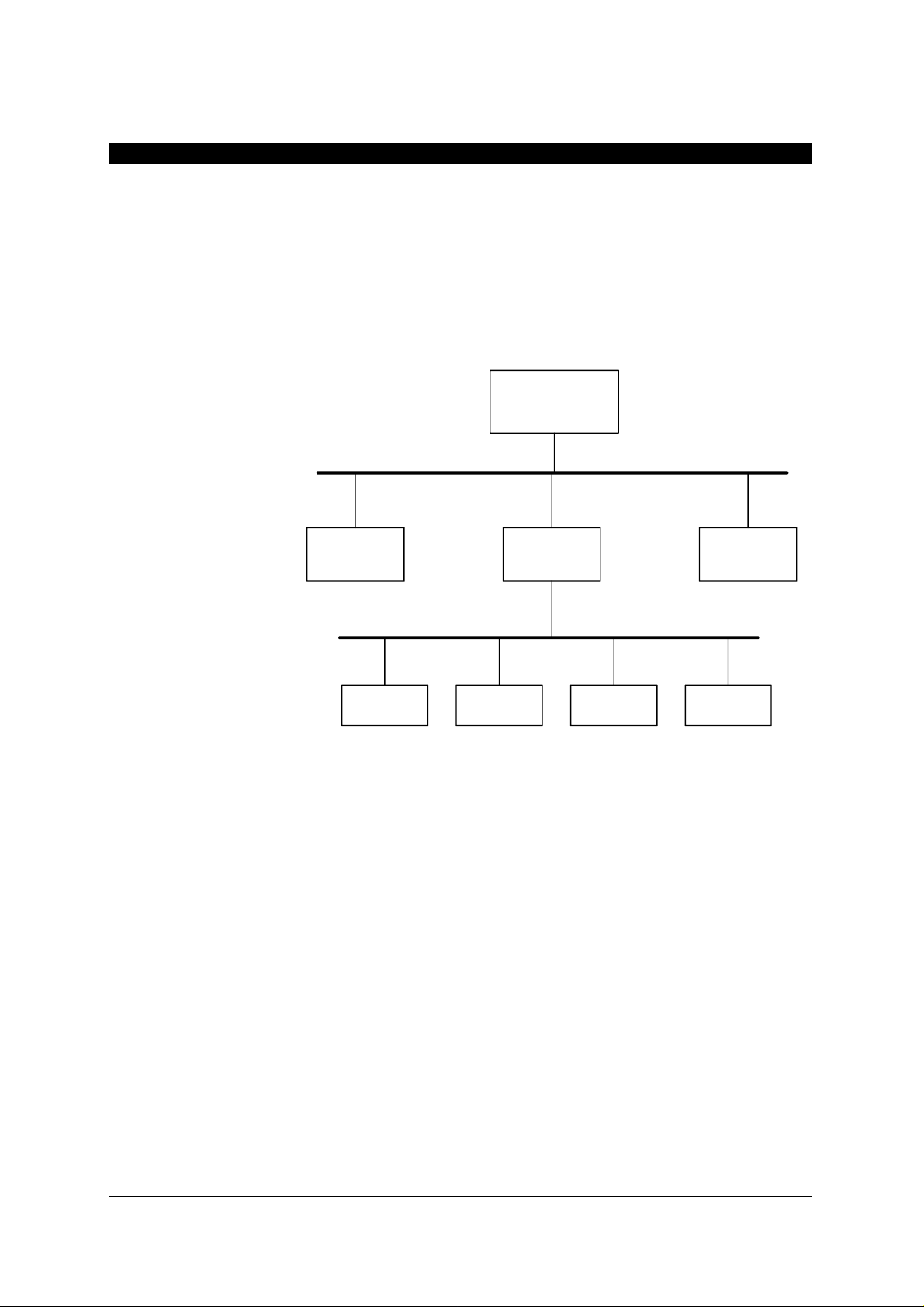
2.1 Gateway connection diagram
The diagram below shows how the gateway is connected to
the PROFIBUS network and to the RS-485 sub-network.
PROFIBUS DP
PROFIBUS network
Master
MCD 3000 – PROFIBUS GATEWAY
DP Slave
RS-485 sub-network
MCD 3000
device
MCD 3000
Gateway
MCD 3000
device
MCD 3000
device
DP Slave
MCD 3000
device
Figure 1. Typical diagram of a PROFIBUS network, a gateway
and an RS-485 sub-network.
A gateway can coexist with a number of other PROFIBUS
nodes, including other gateways. Each gateway constitutes a
single PROFIBUS node, even if it connects to a number of MCD
3000 devices.
MCD 3000
SERIES
8 USER MANUAL
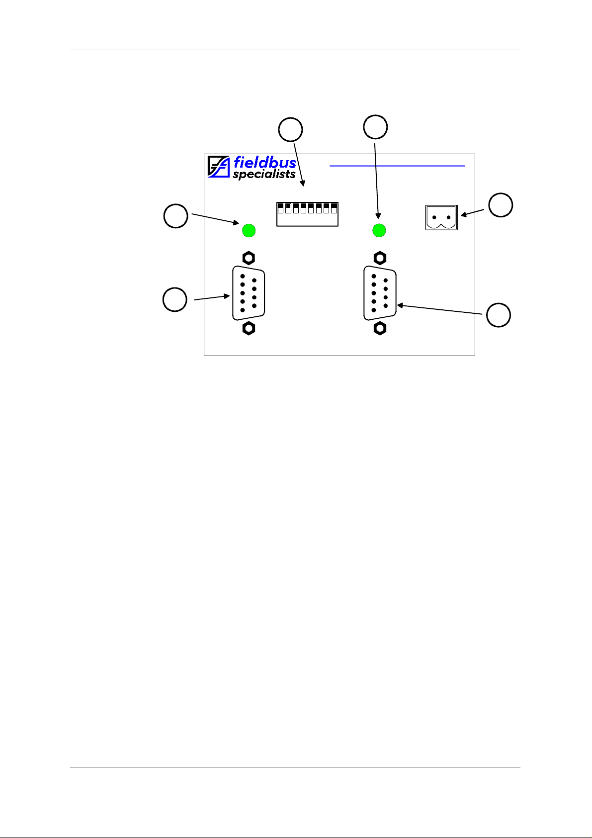
2.2 Front panel
MCD 3000 – PROFIBUS GATEWAY
6
MCD 3000 - PROFIBUS Gateway
RS485
STATUS
5
ADDRESS
1ON2 3 4 5 6 7 8
LSB
RS485
4
PROFIBUS
STATUS
FS-1135
POWER
_
+
24V DC
PROFIBUS
3
1
2
Figure 2. Gateway front panel
Fig. 2 shows the front panel of the gateway. Located on the
front panel are:
1. RS-485 sub-network connector for connecting up to 30
MCD 3000 devices, DB9, male,
2. PROFIBUS network connector, DB9, female,
3. Power connector, 2 pin removable terminal block,
4. Bi-colour PROFIBUS status LED,
5. Bi-colour RS-485 status LED,
6. Dip switches for PROFIBUS address selection.
The following table indicates the status of the PROFIBUS
connection.
MCD 3000
SERIES
9 USER MANUAL

MCD 3000 – PROFIBUS GATEWAY
PROFIBUS
LED
B
R/B
RS-485
LED
B
ANY
Gateway status
Gateway starting (max. 6 sec) or no power
Invalid PROFIBUS address
R/B
G/R/B
G
ANY
ANY
G
ANY
ANY
ANY
R/B
G/R
G
PROFIBUS link down – no PROFIBUS Maste r,
incorrect address or no connection,
PROFIBUS link error – wrong configuration or
parameter in Master
PROFIBUS link up and problem-free
No communication on the RS-485 link
Occasional errors on the RS-485 link
Both PROFIBUS and RS-485 links operational
and error-free
Legend:
- LED off
B
- LED steady green
G
- LED flashing red/off
R/B
LED flashing green/red
G/R
G/R/B
-
LED flashing green/red/off
-
ANY – applies irrespective of LED status
Table 1 – LED Indication
These simple rules may be worth remembering:
- Flashing indicates errors on the relevant link,
- Flashing red means that the gateway attempts to
communicate but fails every time,
- Flashing red/green means that the gateway can
communicate, but errors occur.
MCD 3000
SERIES
10 USER MANUAL
 Loading...