

Page 1
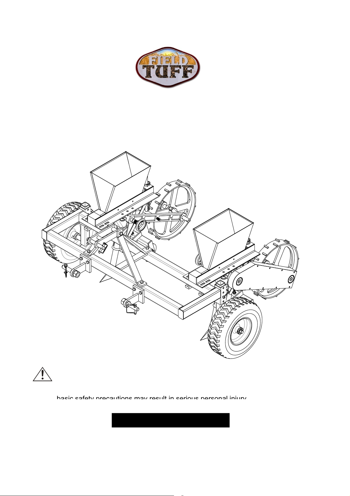
3 PT Corn and Bean Planter
basic safety precautions may result in serious personal injury
OWNER’S MANUAL
WARNING:
Read carefully and understand all ASSEMBLY AND OPERATION
INSTRUCTIONS before operating. Failure to follow the safety rules and other
03132014
Item# FTF-CBP3PT
.
Page 2
Thank you very much for choosing this product! For future reference, please complete the owner’s
pp
pp y p
record below:
Model: ___ FTF-CBP3PT __ Purchase Date: _______________
Save the receipt, warranty and these instructions. It is important that you read the entire manual to
become familiar with this product before you begin using it.
This machine is designed for certain applications only. The manufacturer cannot be responsible for
issues arising from modification. We strongly recommend this machine not be modified and/or used
for any application other than that for which it was designed. If you have any questions relative to a
particular application, DO NOT use the machine until you have first contacted us to determine if it
can or should be performed on the product.
For technical questions please call 1-218-943-6296.
INTENDED USE
Planter is designed for planting larger gardens, food plots or hobby farm.
TECHNICAL SPECIFICATIONS
1. Adjustable row width from 14"-36.6"
2. 22 bushels/hopper, 32 cups/hopper, 1.75 gallons/ hopper, 1 volume bushel=1.25 cubic feet
3. Measurements of hopper: 8"x12" at top, 2"x11.5" at bottom, 8" deep
4. Ground Driven
5. 13" Pneumatic tires
WARNING: Read and understand all instructions. Failure to follow all instructions listed below
may result in serious injury.
CAUTION: Do not allow persons to operate or assemble this planter until they have read
this manual and have developed a thorough understanding of how the planter works.
WARNING: The warnings, cautions, and instructions discussed in this instruction manual
cannot cover all possible conditions or situations that could occur. It must be understood by the
operator that common sense and caution are factors which cannot be built into this product, but must
be su
lied by the operator.
SAVE THESE INSTRUCTIONS
2
Page 3

WORK AREA
control, so visitors should remain at a safe distance from the work area.
orkconditions
s applies to allpersons
so use no
d safety shoes, hardhat,
o co dto s s app es to a pe so s t e o a ea so use o
s d sa ety s oes, a d at,
p
p g g p g
•Keep work area clean, free of clutter and well lit. Cluttered and dark work areas can cause
accidents.
•Keep children and bystanders away while operating the planter. Distractions can cause you to lose
•Be aware of all power lines, electrical circuits, water pipes and other mechanical hazards in your
work area, particularly those hazards below the work surface hidden from the operator’s view that may
be unintentionally contacted and may cause personal harm or property damage.
•Be alert of your surroundings. Using the planter in confined work areas may put you dangerously
close to cutting tools and rotating parts.
PERSONAL SAFETY
•Stay alert, watch what you are doing and use common sense when using the planter. Do not use the
planter while you are tired or under the influence of drugs, alcohol or medication.
•Dress properly. Do not wear loose clothing, dangling objects, or jewelry. Keep your hair, clothing and
gloves away from moving parts. Loose clothes, jewelry or long hair can be caught in moving parts.
•Use safety apparel and equipment. Use safety goggles or safety glasses with side shields which
comply with current national standards, or when needed, a face shield. Use as dust mask in dusty
w
gloves, dust collection systems, and hearing protection when appropriate.
. Thi
in the workarea. Al
n-ski
PLANTER USE AND CARE
•Do not modify the planter in any way. Unauthorized modification may impair the function and/or
safety and could affect the life of the equipment. There are specific applications for which the planter
was designed.
•Always check for damaged or worn out parts before using the planter. Broken parts will affect the
planteroperation. Replace or repair damaged or worn parts immediately.
•Do not exceed the planter load capacity.
•Distribute the load evenly. Uneven loads may cause the planter to tip, resulting in personal injury to
the operator or others.
•Use the planter on flat and level surfaces capable of supporting the planter and its maximum load.
Pulling or pushing a load on a slanted or uneven surface can result in loss of control.
•Storing the planter. When planter is not in use, store it in a secure place out of the reach of children.
ect it for good working condition prior to storage and before re-use.
Ins
3
Page 4
HOBBY SEED PLANTER
worn at all times
Remove the hardware packs and all parts from the cartons
(Patent)
ASSEMBLY AND OPERATING MANUAL
PRE-ASSEMBLY:
Approximate assembly time of this product is 1 hour.
Helpful Tip: Read all instructions before starting to assemble.
WARNING: TG or Field Tuff will not be held liable for any damages,
losses or injury, due to the misapplication or misuse of this product
or for any other reason. Proper eye and hand protection must be
.
TOOLS REQUIRED FOR ASSEMBLY
(2) 14mm Wrenches
(1) 24mm Wrench
(2) 19mm Wrenches
REMOVE ALL PARTS FROM CARTONS
.
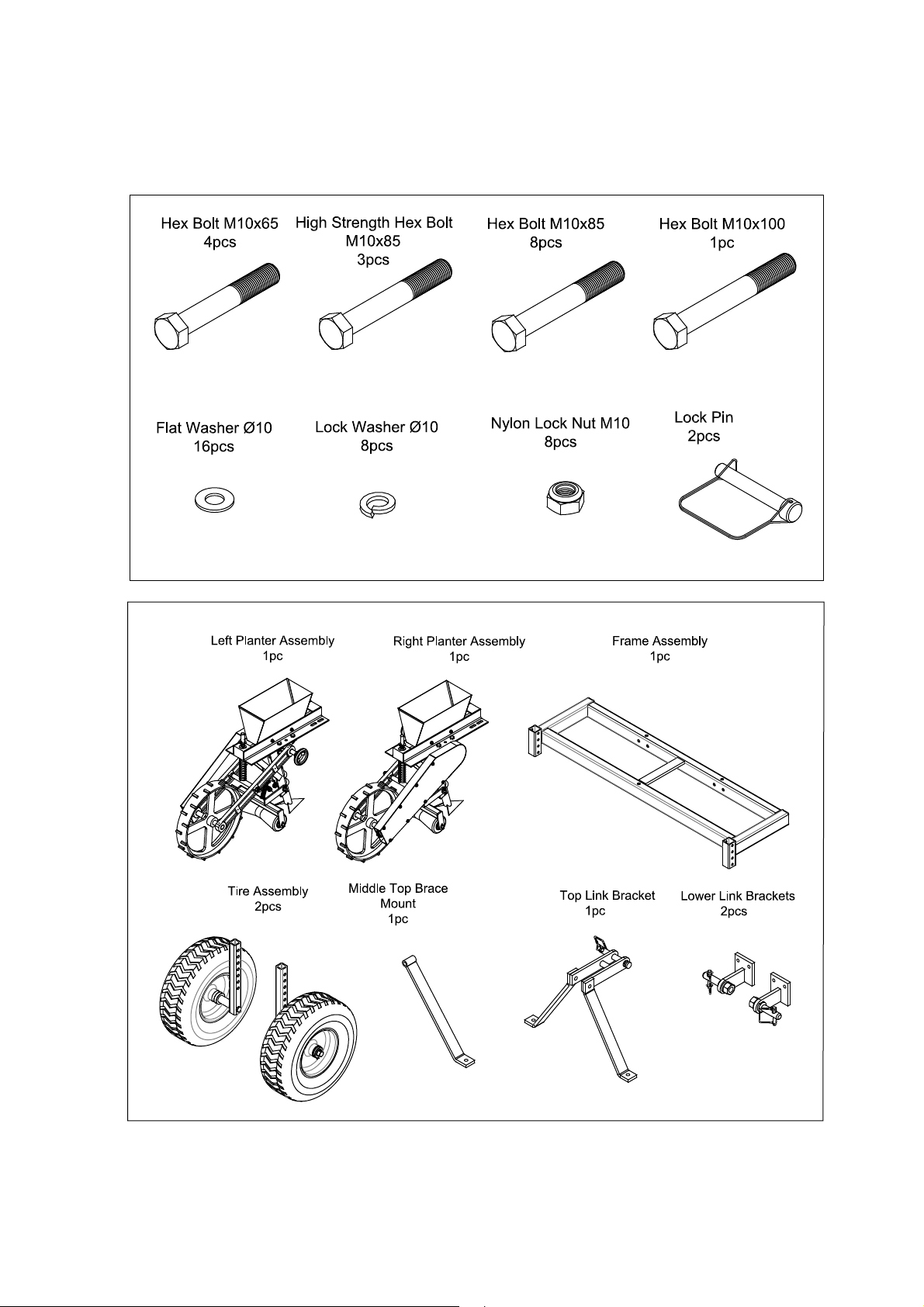
Layout and identify parts included in carton contents. (see carton contents)
Layout and identify parts included in the hardware pack. (see carton contents)
IF ANY PARTS ARE MISSING FROM PACKAGING
Contact 1-218-943-6296 for missing hardware or instructions.
4
Page 5
Carton Contents
5
Page 6
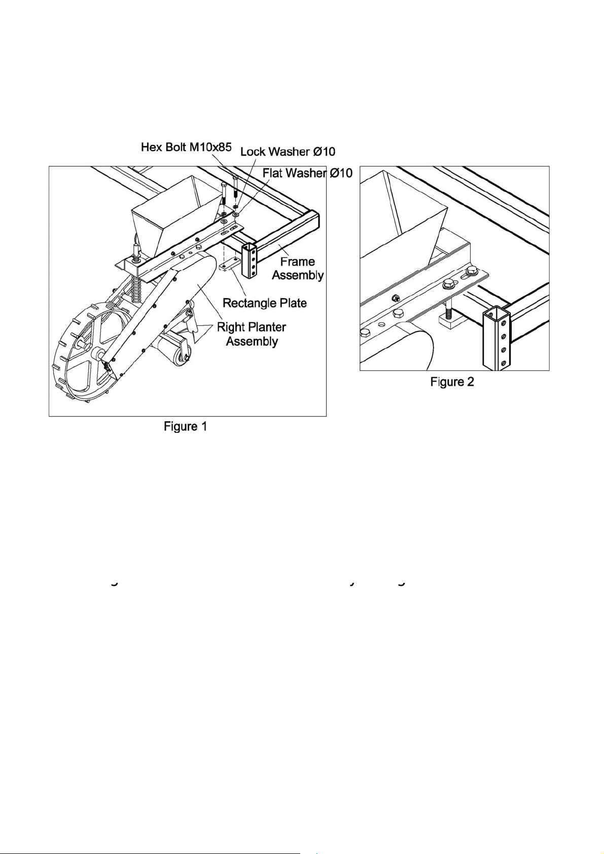
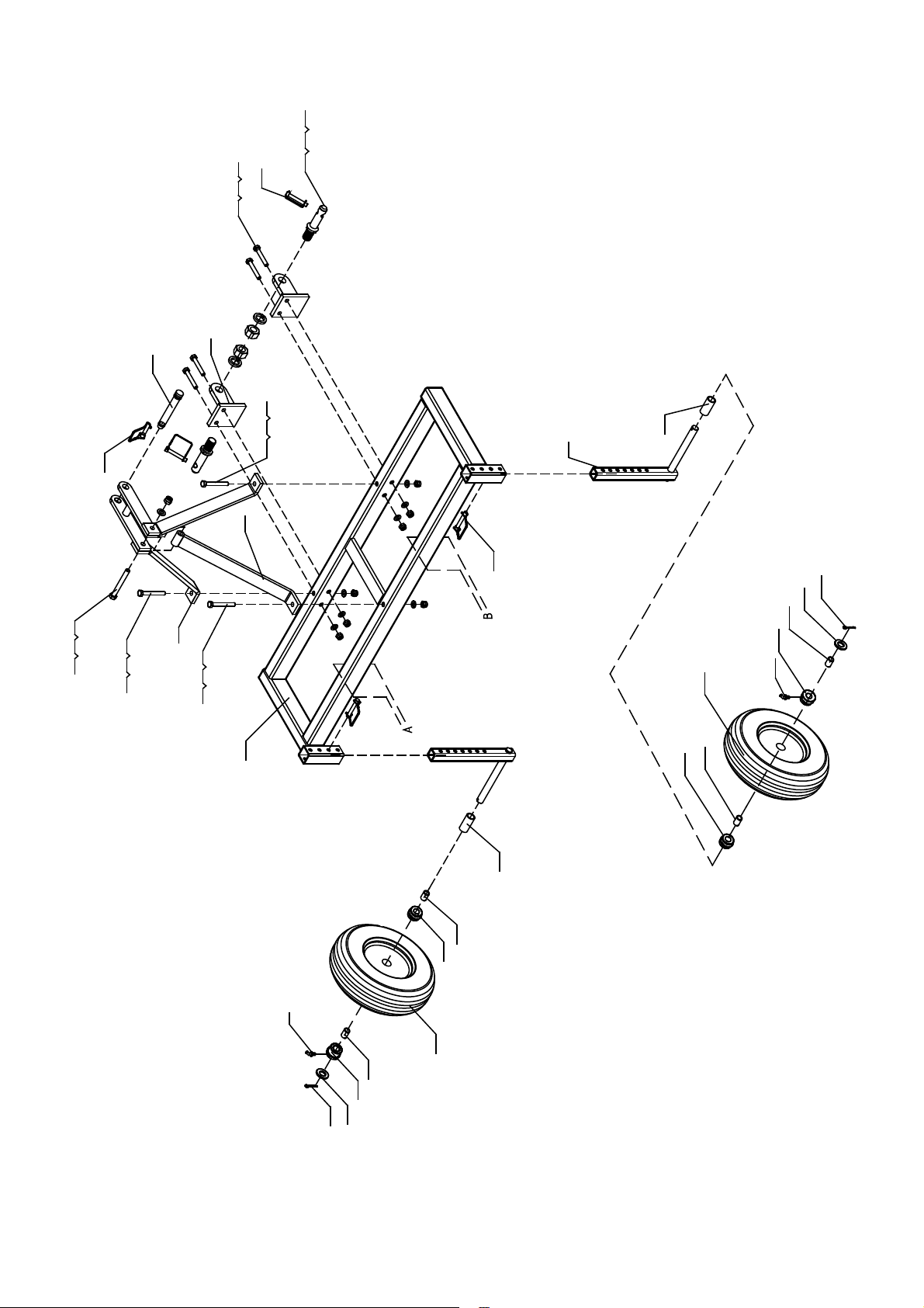
STEP 1: Planter Assembly
gyg
Attach the right planter assembly and hopper bracket to
the right side of the frame assembly using M10 x 85 Hex
Bolt, lock washer Ø10, flat washer as shown in Figure 1.
Repeat above procedure for the left planter assembly.
Figure 2. shows the final assembly for this step.
6
Page 7
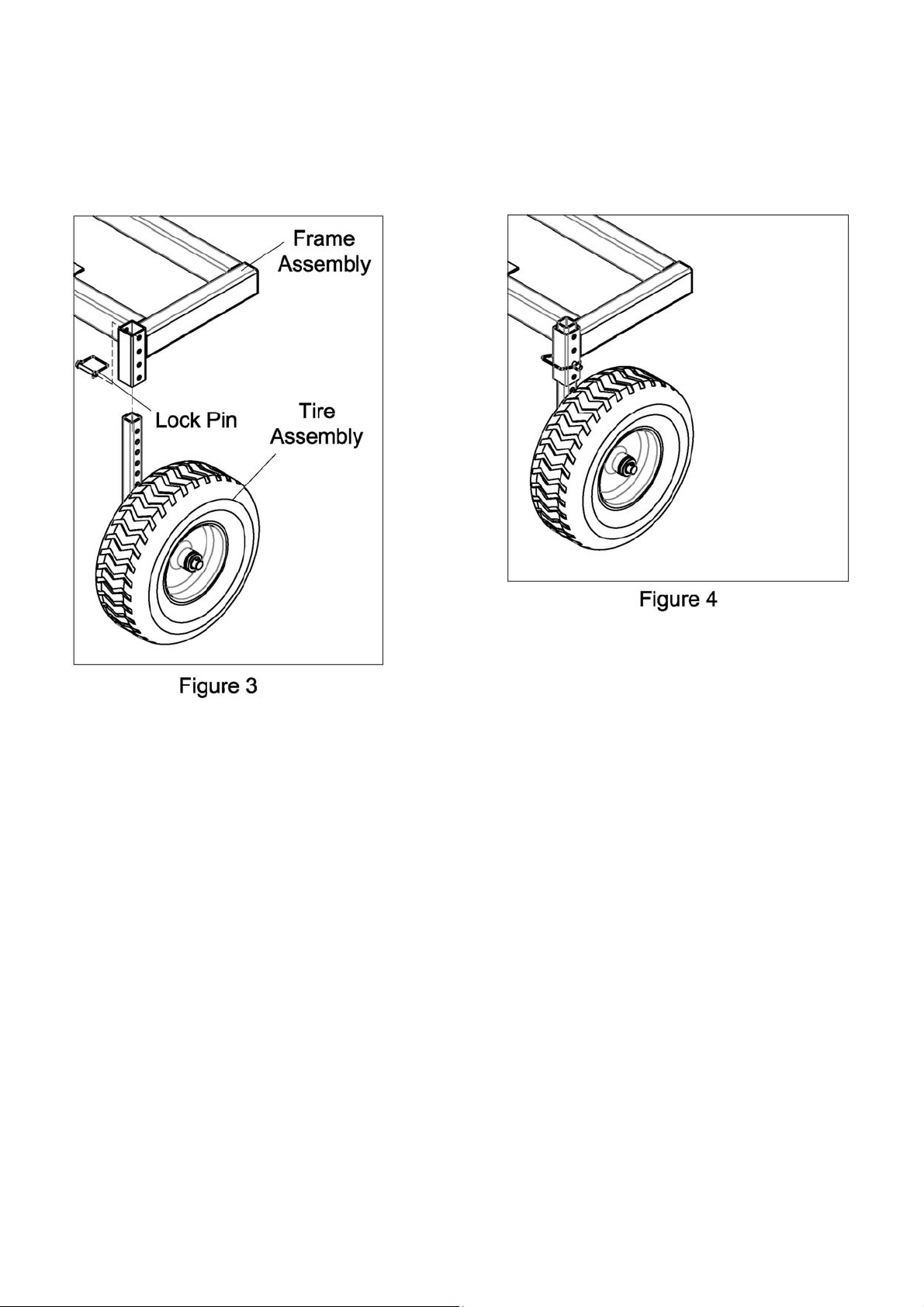
STEP 2: Tire/Wheel Assembly
(Shown in Figure 3)
Insert the tire assembly into the right adjustable axle
receiver tube of the frame Assembly and install Lock pin.
Repeat above procedure for the left side.
Figure 4 shows completed step.
7
Page 8
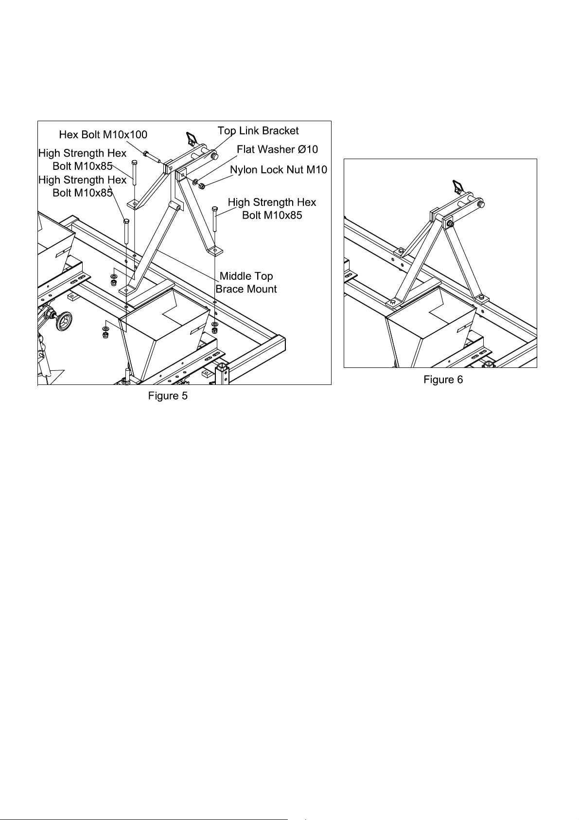
STEP 3: Top Link Bracket and Middle Top Brace Assembly.
Connect top link bracket to the frame assembly using
M10x85 high strenght hex bolt, M10 lock nut, Ø10 flat washer
and tighten, then connect middle top brace to the t op link
bracket and frame using M10x100 hex bolt, M10x85 high
strength hex bolt, M10 lock nut, Ø10 flat washer and tighten.
(Shown in figure 5)
Figure 6 shows the assembled step.
8
Page 9
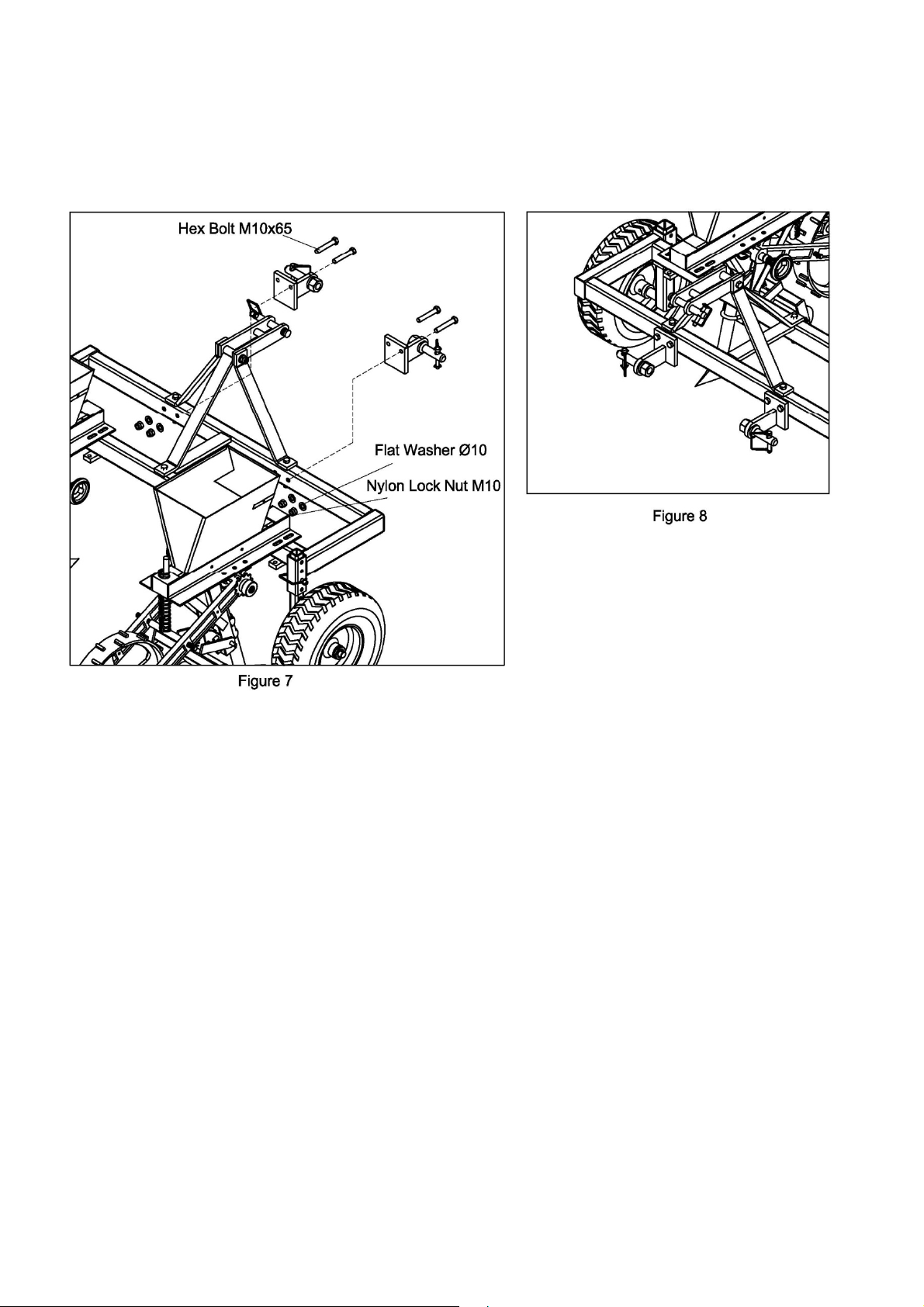
STEP 4: Lower Link Brackets Assembly
Figure 8 shows the assembled step
Install the Lower Link Bracket onto the frame assembly
using M10x65 hex bolt, M10 nylon lock nut,Ø10 flat
washer and tighten. (As shown in figure 7)
.
9
Page 10
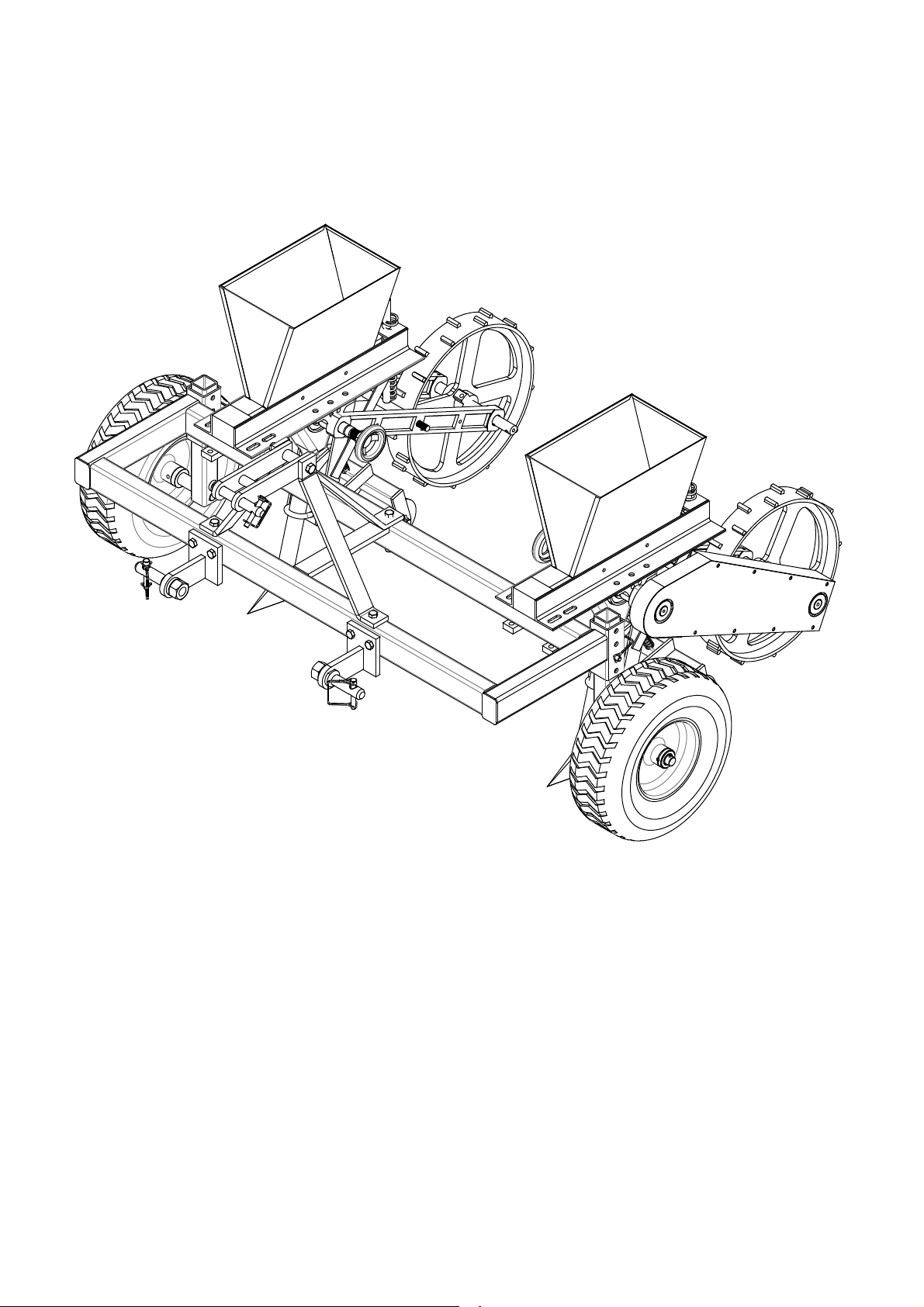
10
Fully
Assembled
Illustraon
Page 11
j g
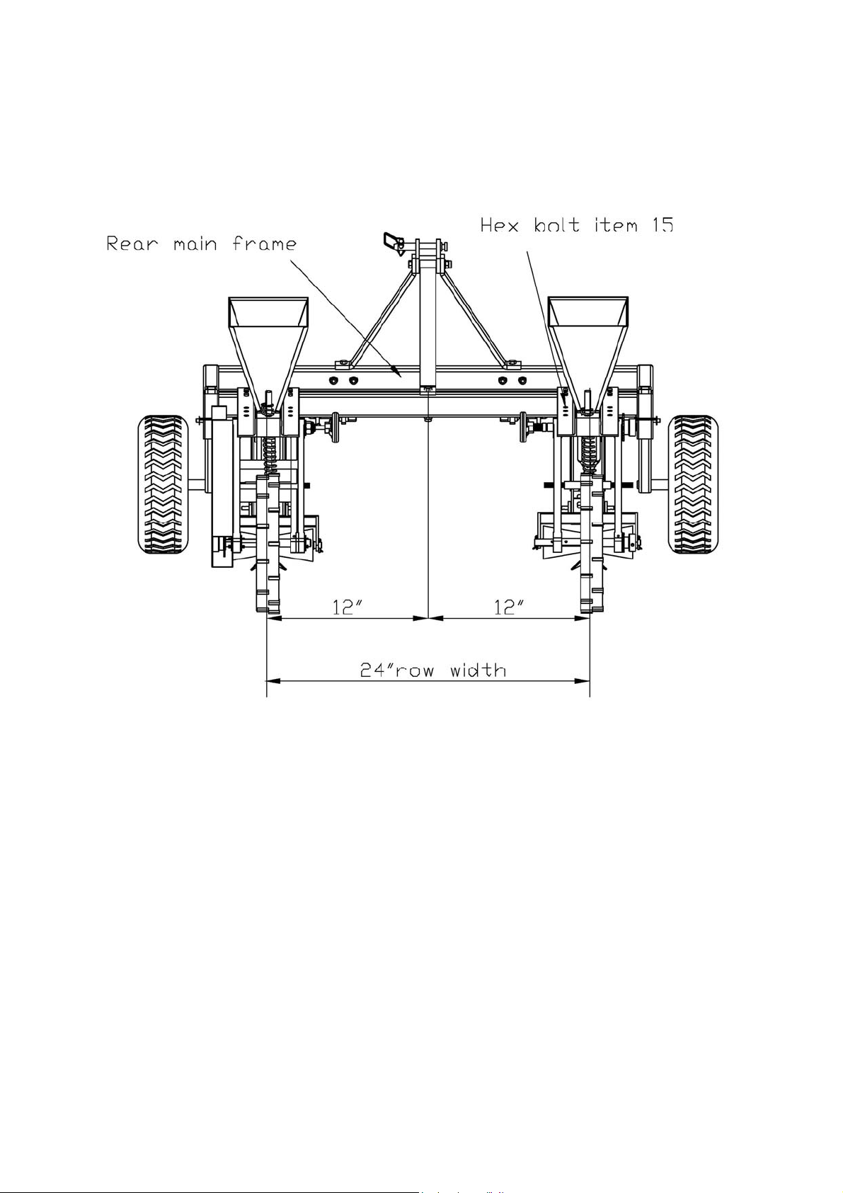
Figure 11
Adjusting Row Width
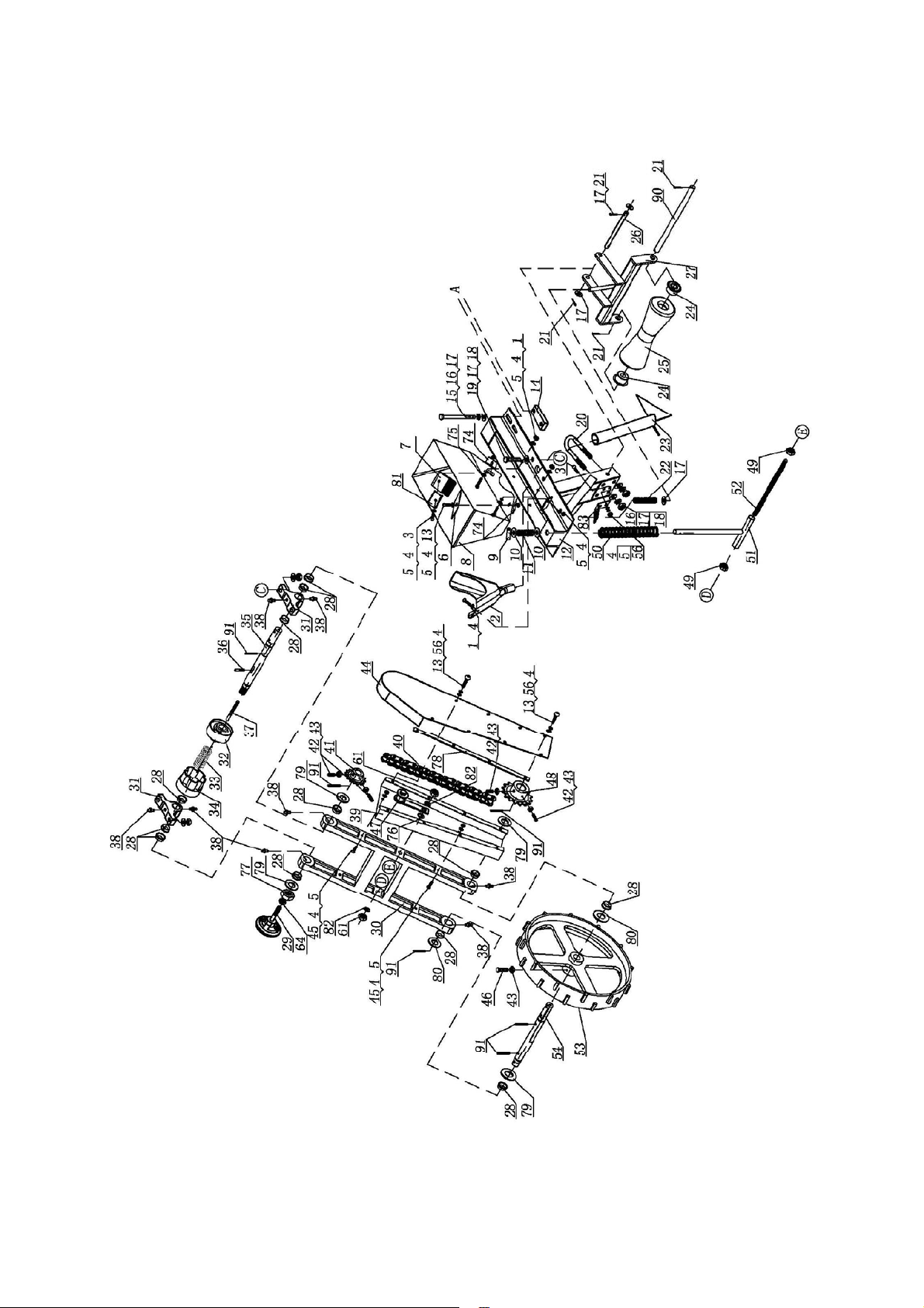
1.To adjust the row width loosen the 4 hex bolts item 15, that fasten the planter
assembly to the rear frame assembly. Measuring from the middle of frame, move the
planter in or out to half the row width. I.e.24” row width measures 12” from middle
frame to the planter assembly. Repeat for opposite planter assembly. See figure 11.
11
Page 12
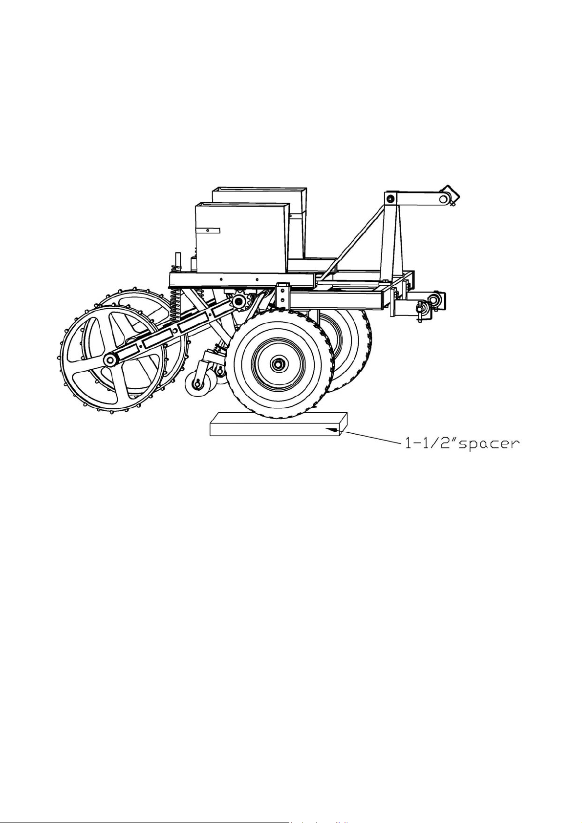
Figure 12
Repeat for opposite side. The planter is now set to plant at the 1
1/2 depth
Setting Planter Seed Depth
1. Attach planter to the tractor with 3pt. Lower Planter to ground and adjust top link so that
planter is level.
2. Lower planter to ground so that coulters sit on flat level surface. See figure 13 of next
page.
3. Raise wheel assembly and place 1-1/2’’spacer under wheel. Install lock pin into the
closest holes in square tube.
-
’’
12
.
Page 13
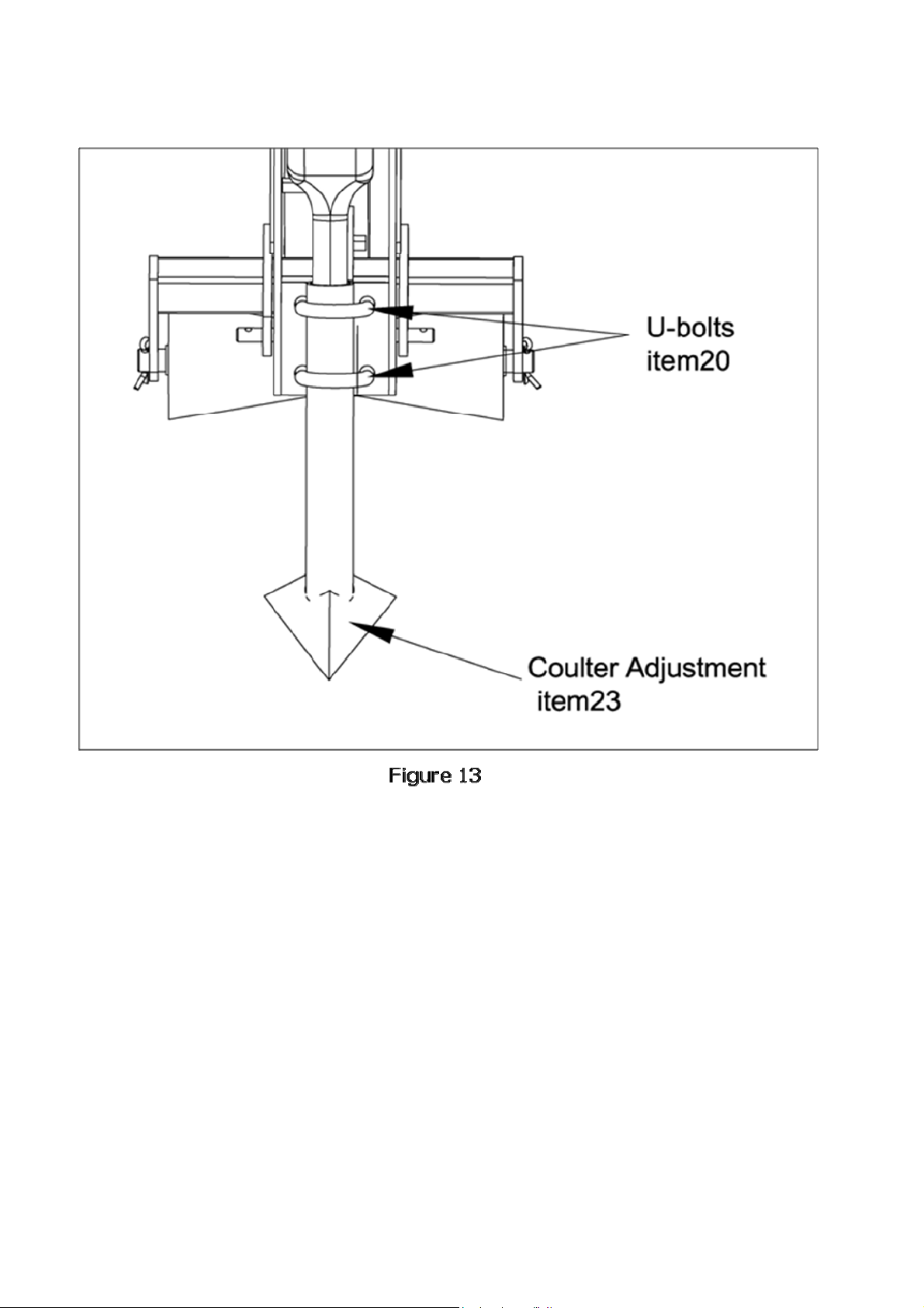
Coulter Adjustment
1.To move coulter assembly down raise planter off of flat surface, loosen the u-Bolts
item 20 and lower coulter assembly down. Retighten U-bolts. See figure 13. Repeat
steps 1 through 3 again, setting planter seed depth.
13
Page 14
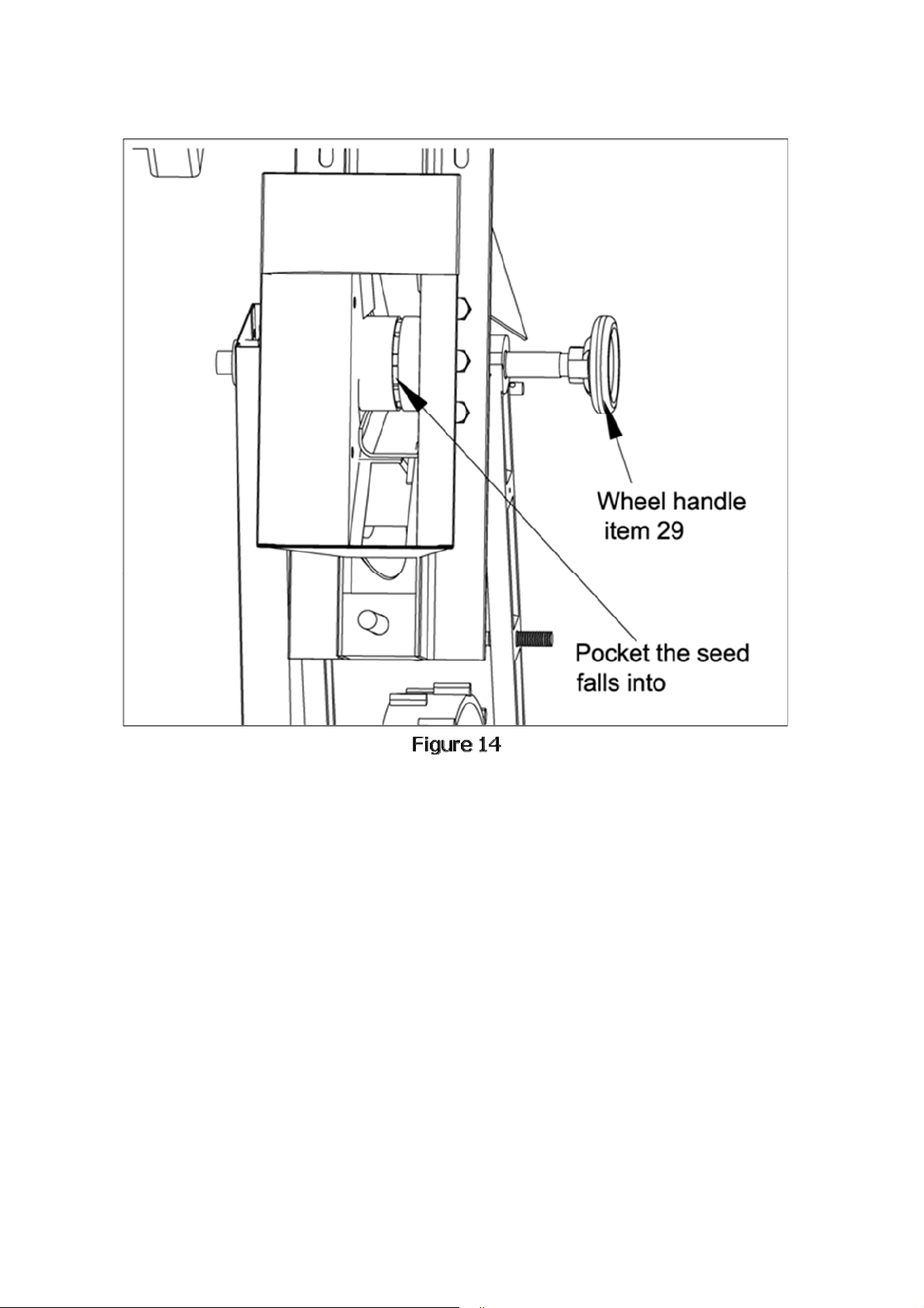
Adjustment for Seed Size
The wheel handle item 29 on the side of planter assembly is used to adjust
the size of the pocket that the seed will fall into and be metered out of the
hopper assembly. Turning the wheel handle clockwise makes the pocket
smaller and counter clockwise enlarges it. See figure 14.
Note: Opening up the pocket so more than one seed will fit into pocket
will give more population of plants.
14
Page 15
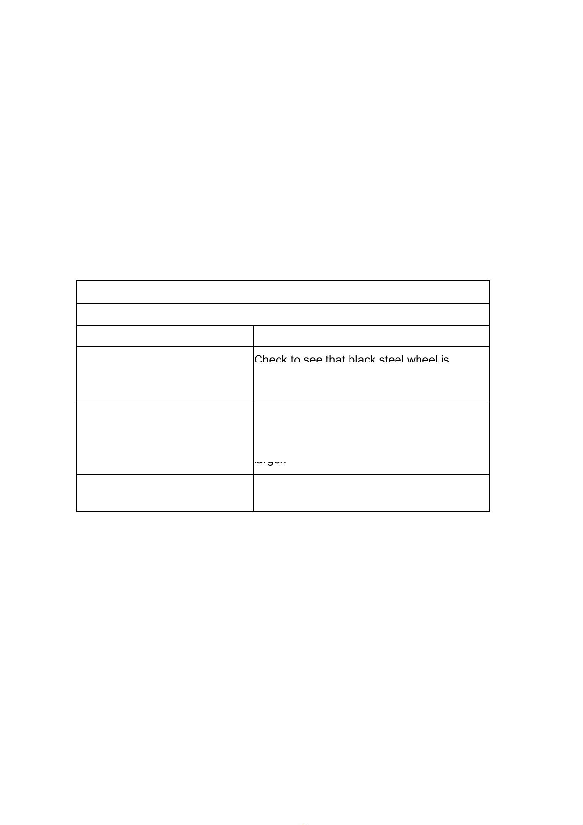
Concept of operation of planter.
plastic hub turns the seed drops into the seed pockets.The seed then
Check to see that black steel wheel is
larger.
As the planter is pulled forward the black steel wheel is ground driven. The
black steel wheel drives the plastic seed hub inside the hopper. As the
travels out the hopper via the seed pocket and then is dropped into seed
tube. The seed then is placed into the ground and then is covered up by
the rear roller.
Trouble Shooting Guide
noituloSmelborP
Planter will not drop seed out of
hopper
Planter dropping seed erratically
Planter not planting seed to the
proper depth.
contacting ground and is rotating when being
pulled forward
Make sure black steel wheel is not sliding on
to loose of soil. Wheel handle(item 29) may
have to be adjusted so the seed pocket is
Reset planter seed depth (Wheels control
depth)
15
Page 16
71 70
1817
73
72
63
62
69
18
17
60
66
68
72
65
72
21
84
1817
1817
58
60
59
1817
60
87
86
85
88
67
86
89
68
86
89
88
87
86
85
84
21
16
Page 17
17
Page 18
18
Page 19
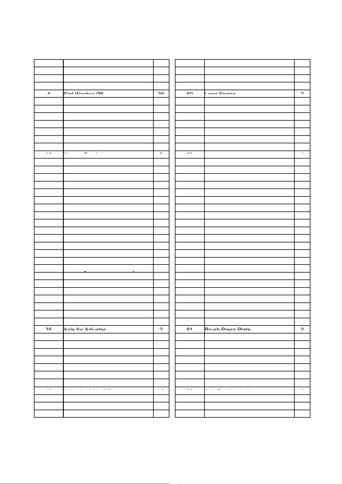
Part List
4
Flat Washer Ø6
3650Long Spring
2
12
H
t
2581
g
y
g y
35
Axle for Adjuster
281Brush Press Plate
2
43
NylonLock Nut M8
1089AxleBushingInsid
2
ytQnoitpircseD
Part No.
5 Nylon Lock Nut M6 22 51 "T" tube Weldment 2
6 Back Plate Inside 2 52 Double End Bolt 2
9 Elastic Cylindrical Pin 2 55 Left Protection Cover 1
10 Flat Washer Ø16 4 56 Lock Washer Ø6 20
opper Bracke
13 Phillips Screw M6x16 18 59 Top Link Bracket 1
14 Rectangle Plate 4 60 High Strength Hex Bolt M10x85 3
15 Hex Bolt M10x85 8 61 Nylon Lock Nut M12 4
16 Lock Washer Ø10 13 62 Lower Link Brackets 2
17 Flat Washer Ø10 34 63 Hex Bolt M10x65 4
19 Hex Bolt M10x35 8 65 Middle Top Brace Mount 1
25 Rubber Covering Roller 2 71 Lock Washer Ø22 2
27 Coverin
31 Bearing Bracket Assy 4 77 Nylon Lock Nut M20 2
34 Control Bushing Inside 2 80 Flat Washer Ø22 4
Roller Frame Ass
.
Part No.
Hex Bolt M10x100
’
ytQnoitpircseD
.
2yellorT740161x6M tloB xeH1
2tekcorpS hteeT 61842reppoH citsalP2
421M tuN xeH94602x6M wercS3
2buH352yssA hsurB7
2tfahS buH452reppoH nroC8
1revoC tfeL752I gnirpS11
201M tuN xeH460201M tuN kcoL nolyN81
2tekcarB leehW664tloB "U"02
1emarF760103x4Ø niP rettoC12
1hsuB recapS862gnirpS llamS22
1’ 4/3 niP 1 taC962yssA retloC32
2tuN074gniraeB42
5 Lock Pin272niP62
2’’8/7 niP 1 taC372
4teksaG4742gniraeB etisopmoC82
46Ø rehsaW giB572eldnaH leehW92
221Ø rehsaW talF672raB tcennoC03
4teksaG872revoC lortnoC23
802Ø rehsaW talF972gnirpS lortnoC33
36 Rod Pin Ø5x30 2 82 Lock Washer Ø12 4
2etalP dettolS38208x8Ø niP doR73
202Ø rehsaW talF48616M gnittiF liO83
39 Right Protection Cover 1 85 Axle Bushing Outside 2
404x91 gniraeB xelpmoC682niahC04
2eriT782tekcorpS hteet 1114
42 Hex Screw M8x25 8 88 Bent Oil Fitting M6 2
e
2elxA relloR gnipmalC091revoC thgiR44
45 Hex Bolt M6x30 4 91 Elastic Cylindrical Pin 12
253x8M tloB xeH64
19
Page 20

For replacement parts and technical questions, please call 1-218-943-6296
Miltona, MN 56354
WARRANTY
One-year limited parts warranty
TG
PO Box 203
MADE IN CHINA
20
 Loading...