

DM SERIES
HIGH PRECISION WEIGHING SCALE
OPERATION MANUAL
PLEASE READ THIS MANUAL VERY CAREFULLY BEFORE
ATTEMPT TO OPERATE THIS SCALE
V118 June 2012
Specifications subject to change without prior notice


CONTENTS
1. INSTALLATION
2. SPECIFICATIONS
3. KEYS, DISPLAY AND CONNECTIONS
4. GETTING STARTED
5. INITIAL SETUP
6. INSTRUCTION FOR USE
7. RS232 DATA OUTPUT MODE
8. TICKET / RECEIPT PRINTING
9. LABEL PRINTING (LP-50 or CPOMPATIBLE)
10. BATTERY POWER AND RECHARGING
11. ERROR CODES
12. DAILY CARE AND MAINTENANCE
Appendix A: -
BI-DIRECTIONAL COMMUNICATION COMMANDS

1. INSTALLATION
Because of metrological legislation, installation/some
metrological parameter settings are limited to be done by
authorized personnel only. Do not attempt to change any of the
built-in parameters. Contact your dealer for installation and
technical assistance.
CAUTION:
This scale is legal for trade only when it is sealed (and/or
stamped) and bearing a serial number. Do not attempt to break
the seal (or stamp) affixed to this scale or remove the serial
number. Contact your dealer for more information and after
sales service.
For most accurate weighing result, do not use the unit in where
or when the environment condition falls beyond as those listed
on SPECIFICATIONS.
Do not attempt to open this scale or conduct any trouble
shootings other than those listed on TROUBLE SHOOTING.
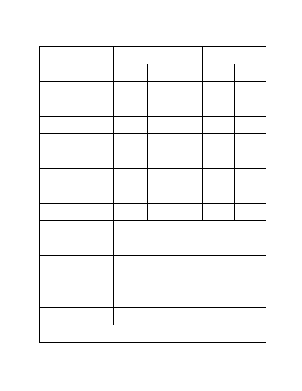
2. SPECIFICATIONS
Model
Capacity [Max (g)]
Readability [d (g)]
W1
W2
d1
d2
DM-3000
3000
Nil
0.1
Nil
DM-3000D
1500
3000
0.1
0.2
DM-6000
6000
Nil
0.1
Nil
DM-6000D
3000
6000
0.1
0.2
DM-10K
10000
Nil
0.1
Nil
DM-10KD
5000
10000
0.1
0.2
DM-20K
20000
Nil
0.1
Nil
DM-20KD
10000
20000
0.1
0.2
Weight Units
kg / g / lb (Weight Unit Conversation Supports
Single Range Models only)
Tare Range
- Max (Subtractive Tare)
Platter
220 x 290mm all Stainless Steel
Dual Power Source
Built-in Rechargeable Battery, and
DC External Power Adaptor
Operation
Environment
15 ~ 35oC. Non-condensed. R.H.≦ 85%
Specifications subject to change prior to notice
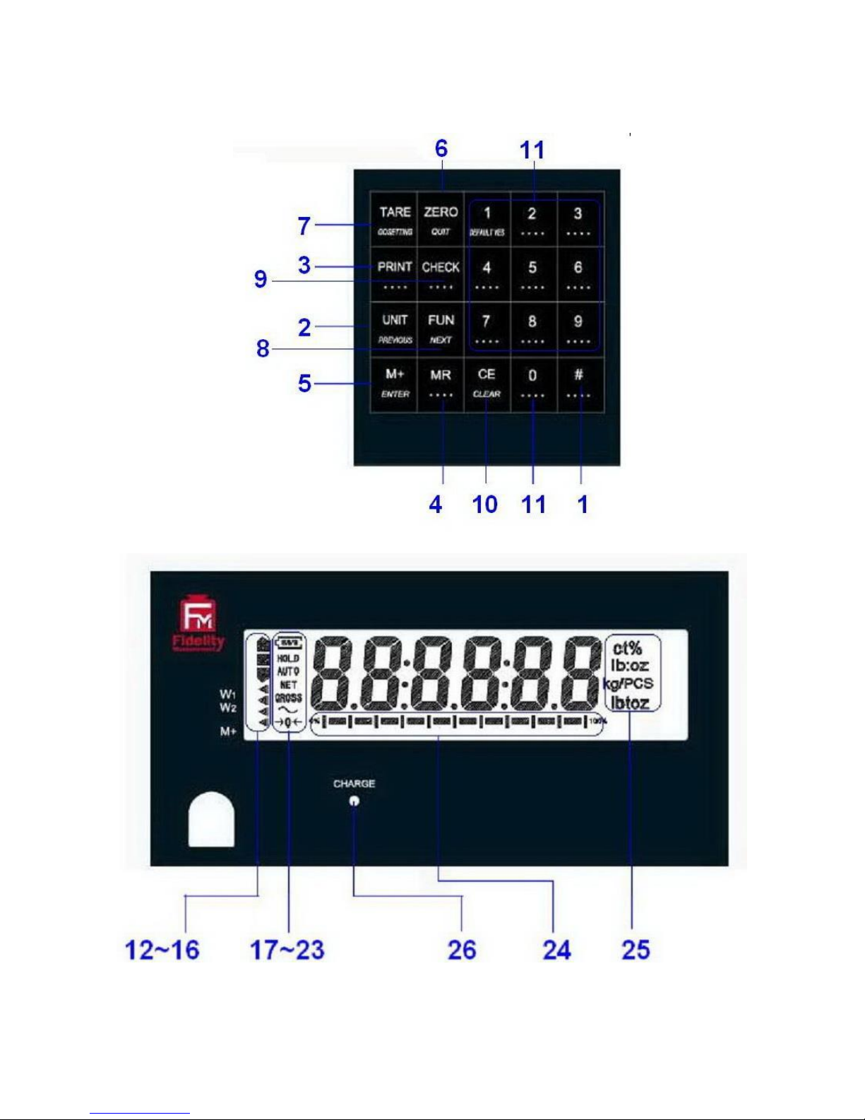
3. KEYS, DISPLAY AND CONNECTIONS

1. SPARE
Spare key, no assignment.
2. UNIT KEY
Press this key to shift among various weight units (if weight unit
conversation is enabled).
3. PRINT KEY1
Press this key to print the results to a computer or a printer through the
RS-232 output.
4. MR KEY
Press this key to recall total stored transactions.
5. M+ KEY
Press this key to accumulate current weight to memory manually.
6. ZERO KEY
Press this key to set weight displayed to zero when an empty scale has
drifted away from a true zero reading.
7. TARE KEY
Press this key to tare off the weight of a container.
8. FUNCTION KEY
Press this key to shift between percentage, piece count and animal2 mode.
9. CHECK FUNCTION
Press this key to start check weighing function and to enter value for HI and
LO limit.
10. CE KEY
Press this key to clear value entered.
1
This key is also used to accumulate the current weight value to memory when F17 is set to
ON.
2
When F11 = ON.

11. NUMERIC KEYS
Numeric keys 0 ~ 9.
12. CHECK SYMBOLS
HI = Checked Value is higher than the HI limit entered,
OK = Checked Value is in between than the low and HI limits entered,
LO = Checked Value is lower than the LO limit entered.
13. W1 INDICATOR3
(When under dual weighing range mode4) Visible when this scale is in the
first weighing range (W1).
14. W2 INDICATOR5
(When under dual weighing range mode) Visible when this this scale is in
the second weighing range (W2).
15. SPARE
Blank, no function assigned.
16. M+ INDICATOR
Visible when the total accumulated weight value is being displayed.
17. BATTERY POWER / LEVEL INDICATOR
Visible to show: -
This scale is being powered by the built-in rechargeable battery,
Remaining battery level.
18. HOLD INDICATOR
(When under animal mode) Visible when weight reading being displayed is
a frozen value.
3
This indicator will not appear when this instrument is in single range mode.
4
This instrument can support two weighing ranges with different maximum capacities (Max)
and different scale intervals (d), each range extending from zero to its maximum capacity.
5
This indicator will not appear when thus unit is in single range mode.

19. AUTO INDICATOR
Visible when this scale is in animal weighing function.
20. NET INDICATOR
Visible when the tare function is in effect. Weight reading shown is net
value.
21. GROSS INDICATOR
Visible when gross weight reading is displayed.
22. STABLE INDICATOR
This indicator appears to indicate the weight detected is in stable condition.
23. ZERO INDICATOR
Visible when this scale is at true zero weight status.
24. CAPACITY TRACK BAR
The ratio (increment = 10%) of applied & remaining weighing capacities are
shown here.
25. WEIGHT UNITS AND FUNCTIONS
% = Percentage (when in Percentage Mode in function),
kg = kilogram,
PCS = Pieces (Piece Count Mode in function),
kg/PCS and g/PCS = Weight per piece (Piece Count Mode in
function),
lb = pound.
26. CHARGE STATUS INDICATOR
Red color: Recharging battery,
Green color: Charging completed.
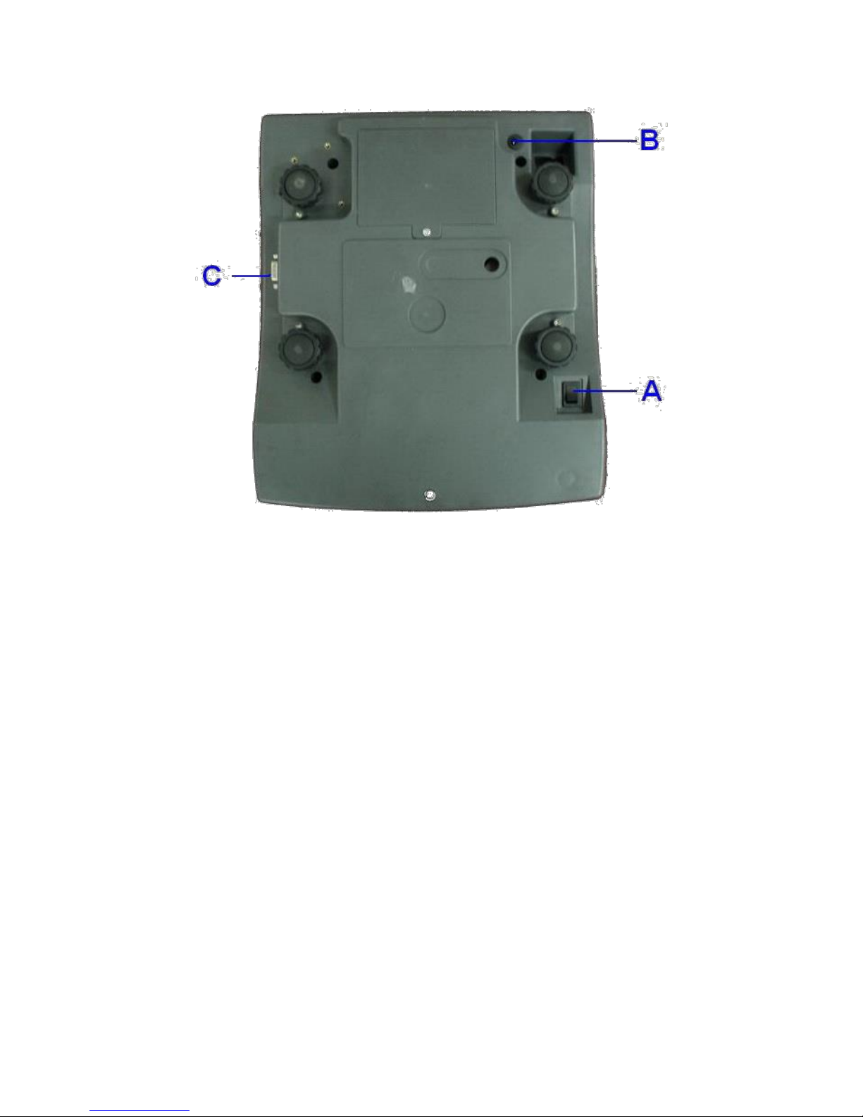
BOTTOM VIEW
A. ON/OFF KEY
Press this key to turn this scale on or off.
B. DC JACK INPUT
External power adaptor is plugged in here.
Output requirements of the power adaptor: -
DC9 ~ 12V 800mA,
Polarity: - Any kind.
C. RS232 COMPORT (DB9)
RS232 communication comport.

4. GETTING STARTED
In order to obtain an accurate weighing result, this scale must be placed on
a strong and level surface. Avoid using this scale in environment where
excessive wind flow, vibration and extreme temperature change exist
General Warning: -
This scale is not an explosion proof device.
This scale is not a water proof device.
Do not open this scale, no user serviceable parts inside. Always
contact your dealer for service.
This scale not to be subject to shock, excessive vibration or
extremes of temperature (before or after installation).
4.1 BUILT-IN RECHARGEABLE BATTERY
This scale is equipped with a built-in rechargeable battery. Before first time
use, recharge it for at least 8 hours to ensure the best battery performance.
4.2 POWER ADAPTOR
Before plugging in the power adaptor, check and make sure the input
voltage of the adaptor matches with output voltage of the electricity outlet. If
not, contact your dealer immediately.
4.3 CONNECTING OTHER DEVICES6
4.3.1 Before Connecting with others
Turn this scale off and cut off power before making any connections or
disconnections.
6
Turn this instrument off before making any connections or disconnections.
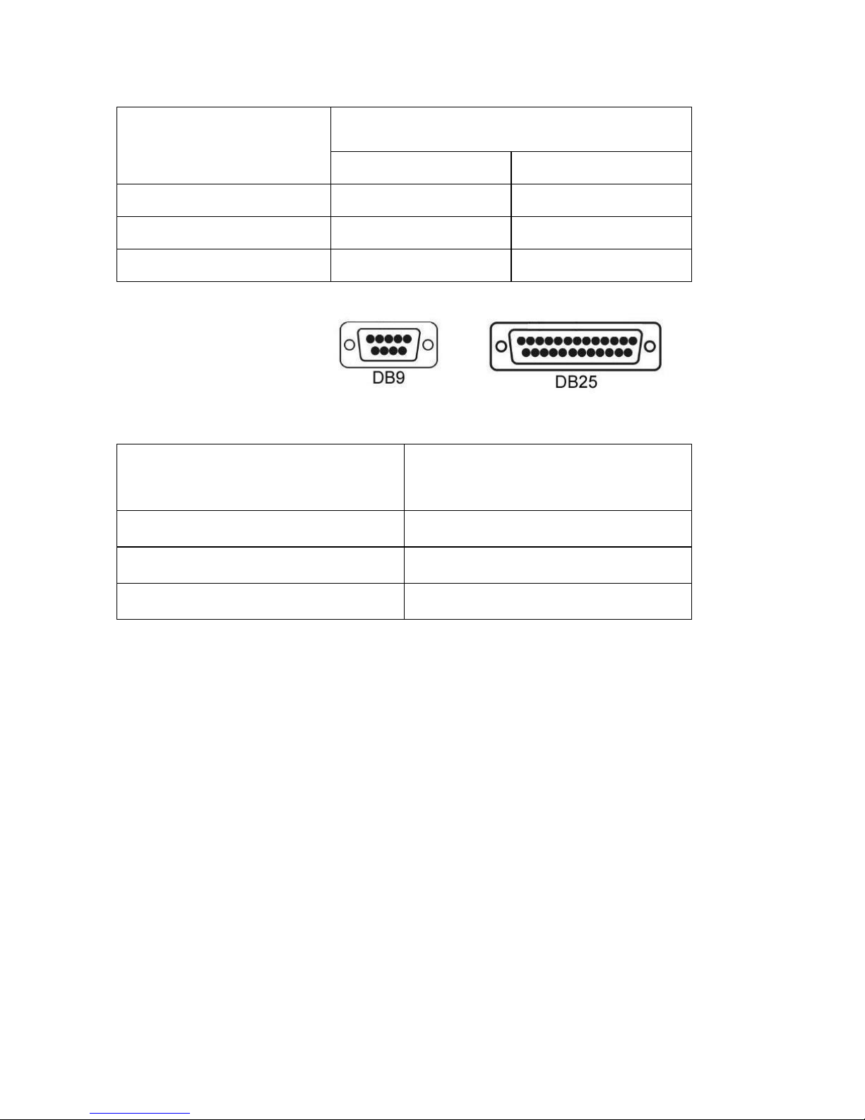
4.3.2. Connecting RS232 to computer
RS232 COMPORT
COM PORT ON COMPUTER
(DB9)
(DB25)
2 = RXD
3 = TXD
3 = TXD
3 = TXD
2 = RXD
2 = RXD
5 = GND
5 = GND
7 = GND
4.3.3 Connecting RS232 to Printer (DB25)
RS232 COMPORT (DB9) ON
SCALE
COMPUTER COM DB25
2 = RXD
3 = TXD
3 = TXD
2 = RXD
5 = GND
7 = GND
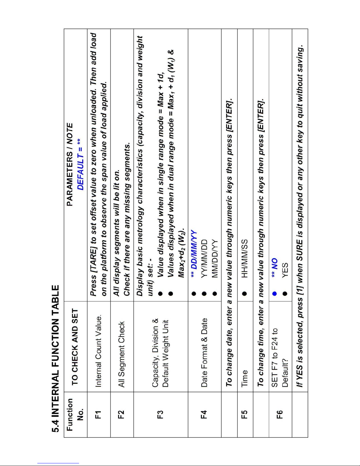
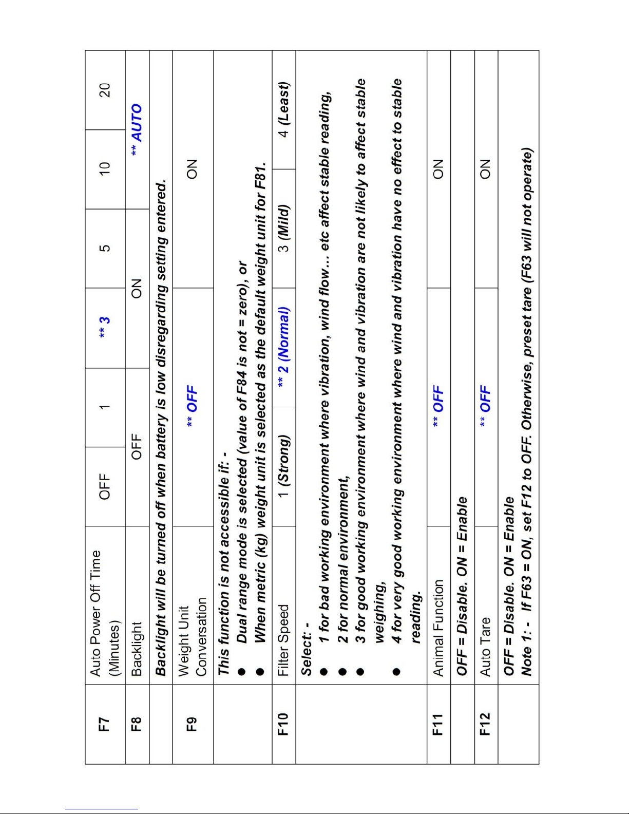
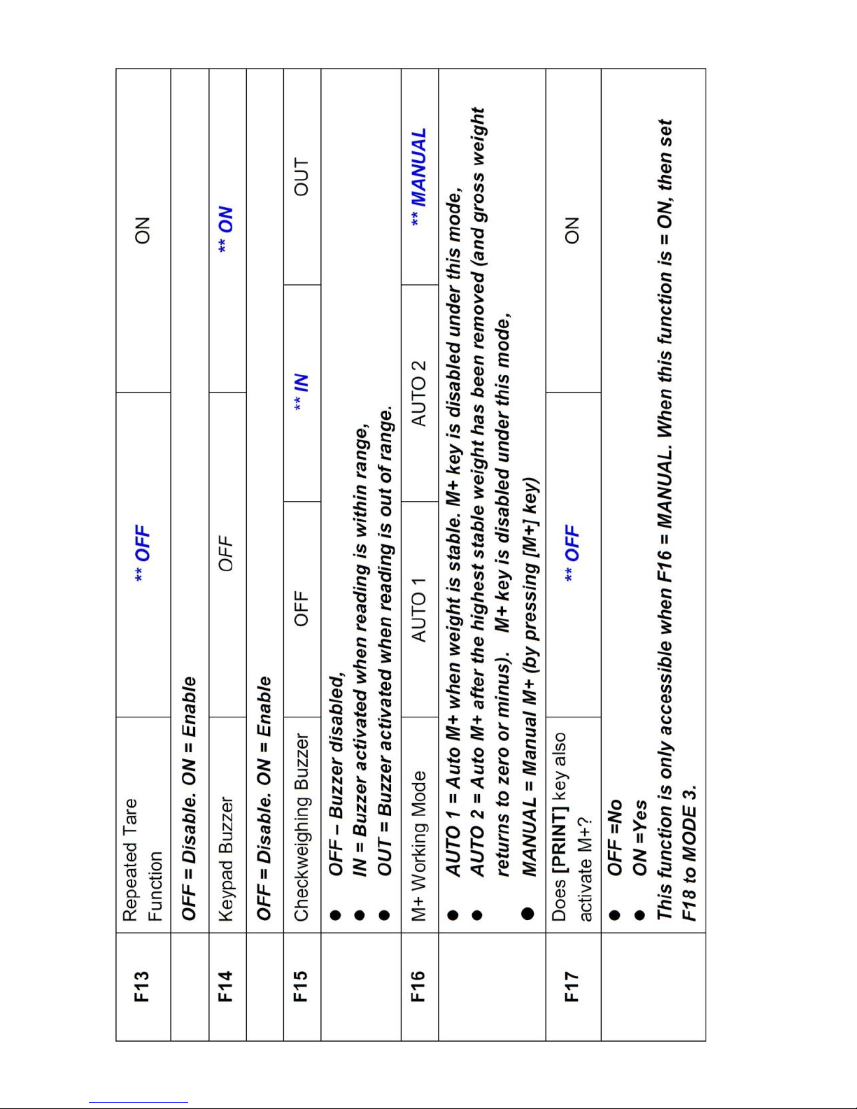
4.4 SETTING UP THE PREFERRED OPERATION PARAMETERS
Set all preferred operation parameters according to 5.4 INTERNAL
FUNCTION TABLE.
NOTE: -
1. F1~F26 are accessible without restriction,
2. F60~F66 are restricted functions which may request a password or
hardware key to access,
3. F80 ~ F99 are restricted functions which may request a password or
hardware key to access. These functions are usually for dealer and
authorized personnel only and all settings these functions are
monitored and recorded. Do not change any setting of these functions
to avoid operation errors.

5. INITIAL SETUP
5.1 INTERNAL SETTINGS
Application parameters can be checked or set through internal setting
functions. Refer to 5.4 for description of all internal functions.
5.2 HOW TO ENTER AND SELECT INTERNAL FUNCTION
Follow the below steps to enter and select desired parameter of an internal
function.
a. Turn this scale off and on again,
b. Press [TARE] during countdown,
c. Display F1,
d. This scale is now in internal function,
e. Quick access to a function number
Press 1 to go to F10,
Press 2 to go to F20,
Press 6 to go to F60 (for dealer and authorized personnel only),
Press 8 to go to F80 (for dealer and authorized personnel only),
Press 9 to go to F99 (for dealer and authorized personnel only),
Press 0 to go to F1,
5.3 KEY FUNCTION DURING INTERNAL FUNCTION MODE
[M+] = Enter, save and return,
[ZERO] = Quit without saving,
[FUN] = Go next,
[UNIT] = Go previous,
[CE] = Clear,
[TARE] = Go to internal function during power on countdown, or set
F1 value being shown to zero and to display the net
span gain by applying additional load applied.


6. INSTRUCTION FOR USE
6.1 POWER ON
Powered on this scale, it will: -
a. Display software number and revision (if any)
b. Display the calibration count value,
c. Display the parameter set count value,
d. Display all display segments,
e. This scale is now ready for operation.
6.2 START WEIGHING
a. If zero weight cannot be obtained when unloaded, press [ZERO]. After
[ZERO] is pressed, the ZERO INDICATOR will appear. Refer to
SPECIFICATIONS for maximum zero range,
b. Always place an object onto platform gently. Excessive force applied
to platform may cause damages to the weight sensor,
c. The weight of the object is displayed automatically,
d. It is a good practice to remove all loads from platform after weighing. It
will prolong the life of the weight sensor.
6.3 ABOUT WEIGH UNIT CONVERSION
The default weight unit is = kg. Depends on the internal settings, this scale
supports also g and lb.
6.3.1 Conversion between Metric Weight Units (kg and g)
When 3 or 4 decimal places (0.000 or 0.0000) is selected in F80, reading in
g is possible during normal operation by pressing [UNIT] disregarding to the
setting of F9.
The weight unit employed before power off will be employed when powered
on again.

6.3.2 Conversion between Metric (kg and/or g) and Imperial7 (lb)
weight units (F9)
This scale supports conversion among kg, g and lb. To enable this
conversion function, set F9 = ON. Press [UNIT] to shift among various
weight units.
The weight unit employed before power off will be employed when powered
on again.
6.4 TARE OFF THE WEIGHT OF A CONTAINER
Tare function is used to temporarily set this scale to zero (such as
cancelling the weight of a box or a container) in order to get the net weight
result
6.4.1 Manual Tare
When a container is used, follow the below steps to tare off the weigh of it
and to get a net weight result.
a. Remove all loads from platform,
b. Make sure that the ZERO INDICATOR is on. If not, press [ZERO],
c. Place container on platform,
d. Press [TARE] ,
e. NET INDICATOR appears to indicator tare is in effect and weight
displayed display is net weight. Refer to SPECIFICATIONS for
maximum tare range,
f. To cancel tare effect, remove all loads from platform and press
[TARE],
g. NET INDICATOR disappears. GROSS INDICATOR appears to
indicator tare effect has been removed and weight displayed display is
gross weight.
6.4.2 Auto Tare8 (F12)
If this function is enabled, this scale will assume the first stable weight
applied is a container and will tare off the weight of it automatically.
7
To comply with the laws of certain countries and approval requirements, the imperial
weight unit may be disabled. Contact your dealer for more information.
8
Set F12 = ON to enable Auto Tare Function

When container is removed and gross weight result = zero, tare effect will
be cancelled automatically.
6.4.3 Repeated Tare (F13)9
When F13 is set to OFF, this scale does not permit multiple tare operation.
Tare effect can only be cancelled when container is removed and gross
weight = zero.
When F13 is set to ON, this scale will permit multiple tare operation
provided that both of the below requirements are met: -
a. The tare operation does not permit a reduction of the value of the tare;
b. The tare effect can only be cancelled when there is no load on the
platform.
6.4.4 Preset Tare (F63)
A pre-determined tare weight can be entered via keyboard. To enable this
function, set F63 to ON, then set also F12 to OFF.
During normal operation, press 0 then followed by the pre-determined tare
weight through numeric keys and press [M+] to enter.
To cancel preset tare effect, remove all loads from platform then press
[TARE].
NOTE: -
1. The pre-determined tare weight entered will be rounded to the nearest
division of this scale. This does not affect the accuracy of the
subsequent weighing and operation.
2. Refer to SPECIFICATIONS for maximum tare range.
3. Manual tare is possible when preset tare is in function.
4. Preset Tare is also governed by Repeated Tare (F13)
9
Set F13 = ON to enable Repeated Tare Function.

6.5 MEMORY ACCUMULATION FUNCTION
6.5.1 To Accumulate a Transaction to Memory10 11 12
a. Press [M+]13 to save and accumulate data of current transaction to
memory,
b. This scale displays “≡ n”. M+ INDICATOR appears to indicate that
memory contains stored data. “≡ n”” means the total number of
transactions accumulated to memory,
c. This scale returns to normal display status after 2 seconds,
d. Repeat a to c for subsequent transactions14,
NOTE: -
1. Unstable weight cannot be accumulated to memory. If M+ is
pressed when weight reading is not unstable, this scale will reject
this command and response with 3 beeps.
6.5.2 Memory Recall and Clearance
a. Press MR to recall total accumulated weight from memory,
b. After MR is pressed, This scale displays “≡ n” (n means the number
of transactions accumulated) follow by the total accumulated weight
stored in memory,
c. At this point: -
Press [ZERO] to quit, or
Press [ZERO] followed by [CE] to clear memory and return operation.
M+ INDICATOR disappear to indicate no data is stored in memory.
6.6 FUNCTION MODES
This scale is equipped with the below function modes: -
Piece Count,
Percentage,
Animal weighing (When F11 = on),
Checkweighing (HI/LO check) for above functions.
10
Memory Accumulation Function support weighing function only.
11
Weight less than 20d (or 20d1 for dual range) will not be accumulated to memory.
12
All data stored will be erased when this instrument is powered off.
13
or press [PRINT] if F17 is = ON
14
Weight must return to or below zero to enable another weight accumulation.

6.7 TO ENTER AND QUIT FROM SUPPLEMENTARY FUNCTION MODE
6.7.1 To Enter a Function Mode: -
Press [FUNC] to shift among Piece Count (CoUnt), Percentage (PErCnt),
Animal weighing (Ani) modes and press [M+] to enter when the desired
mode name is being displayed.
6.7.2 To Enter and Quit from a Function Mode
To change enter a specific supplementary function mode, press
[FUNC] until the desired supplementary function mode appears.
Then press [M+] to enter,
To quit from a supplementary function mode, press [FUNC] followed
by [ZERO].
6.8 PIECE COUNT FUNCTION15
Follow the below steps to enter Piece Count Function: -
a. Refer to 6.3 on how to select the desired weight unit,
b. If a container is used, place it onto the platform and press [TARE],
c. Press [FUNC] to shift among various functions until Piece Count
(CoUnt) appears,
d. Press [M+] to enter,
e. Default16 sample size and PCS INDICATOR appear.
f. This scale is now in Piece Count Function.
g. Refer to 6.8.1 for subsequent operation procedures.
6.8.1 Sampling Process
a. Put samples with same quantity on platform then press [M+]. Should a
different sample size is required, enter the quantity of the sample size
through the numeric keys17,
b. Apply samples with the same quantity as being displayed on this
scale18 and press [M+],
c. This scale will calculate, store the average piece weight and confirm
15
Piece Count Function Mode does not support memory accumulation (M+) function.
16
Default sample size value = 50 pieces
17
Usually, the more the sample size, the better the counting accuracy.
18
Although there is no restrictions on the minimum average price weight, for counting
accuracy, it is recommended that the average piece weight should not be less than 0.25d
or 0.25d1 (dual range mode)

with 2 beeps. The quantity applied to platform is then displayed,
d. Sampling process is now completed,
e. Add to or remove from the platform, the corresponding quantity will be
displayed automatically.
NOTE: - To count different articles, press [FUNC] and repeat procedures
listed on 6.7 and 6.7.1.
6.8.2 Shift among Quantity, Average Piece Weight and Weight Info
a. Press [UNIT] to shift among quantity, average piece weight and
weight info,
b. Quantity Display format = numeric numbers & PCS (e.g1000 PCS) ,
c. Average piece weight display format = numeric numbers & weight unit
& / (slash) & PCS (e.g. 499.960g/PCS) ,
d. Weight display format (when Piece Count Function is in effect) =
numeric numbers & weight unit & PCS (e.g. 500 kg PCS).
6.8.3 To quit Piece Count Function19
Refer to 6.7.2 on how to quit and back to weighing function.
6.9 PERCENTAGE FUNCTION20
Follow the below steps to enter Percentage Function: -
a. Refer to 6.3 on how to select the desired weight unit,
b. If a container is used, place it onto the platform and press [TARE],
c. If a reference mass (mass value which is considered as 100%) is
available, apply it on platform. NOTE: - If reference mass is not
available or reference mass value will be entered through numeric
keys, then ignore this step,
d. Press [FUNC] to shift among various functions until Percentage
Function (PErCnt) appears,
e. Press [M+] to enter,
f. Reference mass value can be entered by anyone of the below
methods: -
By applying the reference mass onto the platform during
19
After quit, the average piece weight stored will be erased.
20
Percentage Function does not support memory accumulation (M+) function.

abovementioned step c, or
In case there is no reference mass applied to platform, the last
reference mass used will be displayed. Press [M+] to confirm, or
In case of new reference mass value, enter it through numeric
keys and press [M+] to confirm. After a new reference mass is
entered, this scale shows 0% to indicator there is no load applied
to platform,
g. This scale is now ready for percentage calculation.
6.9.1 To Quit Percentage Function21
Refer to 6.7.2 on how to quit and back to weighing function.
6.10 ANIMAL WEIGHING FUNCTION22 23 24
Follow the below steps to enter Animal Weighing Function: -
a. Refer to 6.3 on how to select the desired weight unit,
b. If a container is used, place it onto the platform and press [TARE],
c. Press [FUNC] to shift among various functions until Animal Weighing
Function (Ani) appears,
d. Press [M+] to enter,
e. Display last filter (FLt) value applied. Select the preferred filter value25
by pressing [FUNC] or [UNIT] key, 3 filer values are available: -
FLt 1 = Fast
FLt 2 = Normal (For human weighing, select this parameter),
FLt 3 = Slow
f. Display the last weight release variation value (rE) applied. Under the
animal weighing function, this scale will hold a weight result until the
pre-defined weight release variation value is achieved,
g. Select the preferred weight release variation value by pressing [FUNC]
or [UNIT] key. 5 auto release range values are available: -
21
After quitting, the average piece weight stored will be erased.
22
To enable animal weighing function, set F11 = ON
23
Weight reading of Animal weighing function cannot be accumulated.
24
Animal Weighing function will not operate when weight is less than 20d (or 20d
1
for dual
range).
25
It is a trade off between motion filtering and accuracy. The faster the filter, the lower the
accuracy; The slower the filter, the higher the accuracy. It is recommended that FLt 3
should be applied first. Should situation require, change to a lower FLt number.

rE oFF = auto release disabled,
rE 2 = auto release when weight varies ≥2% of rate capacity (or
W1 for dual range),
rE 5 = auto release when weight varies ≥5% of rate capacity (or
W1 for dual range),
rE 10 = auto release when weight varies ≥10% of rate capacity
(or W1 for dual range),
rE 20 = auto release when weight varies ≥20% of rate capacity
(or W1 for dual range),
h. Press [M+] to enter,
i. Display Ani. AUTO INDICATOR appears to indicator Animal Weighing
Function is in effect.
6.10.1 Weighing Animal
a. Get animal on platform,
b. This scale will calculate the mean weight of an animal or a group of
animals. The result obtained will be displayed. HOLD INDICATOR
appears to indicate that this weight value is being held (frozen)26,
c. Get other animals on platform in case more animals have to be weight
in the same transaction,
d. An updated weight will be calculated and displayed27 as above step
b.
6.10.2 To Update Weight Value Manually
To update the weight reading manually, press [ZERO].
6.10.3 To Quit Animal Weighing Function
Refer to 6.7.2 on how to quit and back to weighing function.
After quitting, the AUTO indicator disappears to indicate that Animal
Weighing is no longer in effect.
26
When weight value is being frozen, weight unit conversion is not possible.
27
Provide that extra weight added fulfill the weight release variation value listed on 6.10 step
g.

6.11 CHECKWEIGHING MODE28 29 30
This scale is equipped with various checkweighing modes. See F25 for
check modes availability.
6.11.1 To Trigger Checkweighing Mode 1 and Mode 2
Follow the below steps to trigger checkweighing mode 1 and Mode 2: -
a. During normal operation (of a function), press [CHECK].
b. The current HI limit is displayed with the Hi symbol on, press [M+] to
confirm, or
c. Enter a new HI limit through the numeric keys and then press [M+],
d. Display current LO limit with the Lo symbol on, press [M+] to confirm,
or
e. Enter a new HI limit through the numeric keys and then press [M+]
f. Checkweighing function is now enabled. The check is result is shown
by one of the HI/OK/LO symbols,
g. The same result will be sent to the relay module (if ordered) together
with the buzzer signal.
NOTE: -
1. For normal comparison, set both HI and LO limits,
2. To check only if result is lower than or equal to LO (result ≤ LO?), set HI
limit = 0,
3. To check only if result is higher than or equal to HI (result ≥ HI), set LO
limit = 0,
4. To check if result is equal to a specified value, set both HI limit and LO
limit = the specified value
6.11.2 To Trigger and Set Parameters for Mode 3 and Mode 4
Contact your dealer for more information.
28
Checkweighing mode will not operate when weight is less than 20d (or 20d1 for dual
range).
29
Set also F15 for desired Checkweighing buzzer output.
30
When F25 = Mode 1, set also F26 (Near Zero weight value).

6.12 STANDARD CHECK-WEIGHING MODE (WHEN F25 = MODE 1)31: -
This mode is used to compare the weight reading obtained with the preset
HI and LO limit set to this scale. The comparison result (HI, OK or LO) will
then be displayed with or without buzzer32.
If a relay module is installed, the comparison results are also sent through
the relay module.
Standard checkweighing mode can be activated during the below functions
mode. Bracketed are the targets to be checked under various functions.
Weighing (weight value),
Piece Count, (number of pieces),
Percentage (percentage value),
Animal Weighing (actual weight value33).
6.13 INFLOW/OUTFLOW CONTROL LOGIC
The inflow/outflow logic mode is built-in the software to simplify the control
system.
To achieve direct inflow/outflow control, LO output should be connected and
used control start/stop of the inflow device; while HI output should be
connected and used to start/stop of the outflow device.
Refer to DIAGRAM: - INFLOW / OUTFLOW for more information of this
control logic.
6.14 ABOUT NEAR ZERO VALUE (F26)
Nero zero value is useful for both dynamic weighing applications. It is used
to avoid false LO signal when a load is approaching and leaving the
weighing platform.
HI/OK/LO comparison will only start when weight reading exceeds the near
zero value entered. Refer to DIAGRAM: -NEAR ZERO VALUE for more
information.
31
Before using this function mode, set preferred near zero weight value in F26. System will
ignore any near zero value entered which is less than 20e. If it is the case, system will use
20e as minimum near zero weight value. For static weighing application, set near zero
value to zero.
32
Set F15 to obtain the required buzzer output configuration.
33
Despite the weight value is being held (frozen), this instrument will still detect continuously
the actual weight applied to the platform, compare this actual applied with the HI and LO
limits set and present the comparison result based on the actual weight applied.

6.15 TO QUIT CHECKWEIGHING MODE
To quit / stop checkweighing mode, set both HI and LO limits to zero.
DIAGRAM: - INFLOW / OUTFLOW
DIAGRAM: - NEAR ZERO VALUE

7. RS232 DATA OUTPUT MODE
There are 3 data output modes are available34. : -
Mode 1 and Mode 2 are for communication with computer and other
peripherals which accepts and processes continuous data
communication,
Mode 3 is for transmission to printer or other peripherals which accept
only single or manual data transmission.
7.1 AUTO WEIGHT FORMAT STRING35 36
Data is transmitted in ASCII code. Data format is listed on below table.
DATA BIT
DESCRIPTION
1~2
MOTION STATUS
US = UNSTABLE
ST = STABLE
3
COMMA SEPARATION
4~5
NET/GROSS
NT = NET WEIGHT
GS = GROSS WEIGHT
6
SIGN (Sign of weight reading)
Positive = space. Negative = minus (-)
7~13
WEIGHT VALUE
7 digits weight value including location of decimal point. If
there is no decimal point, then the first character = space.
14
COMMA SEPARATION
15~16
UNIT
kg = kilogram
lb = pound
17
Cr
18
LF
34
Refer to F18 for more information.
35
When F18 is either set to MODE 1 or Mode 2
36
Overloaded weight will not be sent.

8. TICKET / RECEIPT PRINTING
If a ticket/receipt printer is used, select Mode 3… normal should be
selected in internal function F18.
8.1 STANDARD PRINT OUTPUT FORMAT37 38
Standard ticket/receipt printout of various function modes are illustrated
below. Press [PRINT] for manual output or set F17 = ON for automatic
output.
8.1.1 Standard Output Print Format
8.1.1.1 Weighing function
7 lines will be transmitted as below: -
1. Time of print,
2. Date of printing,
3. Transaction sequent number (if this transaction is accumulated to
memory),
4. Net weight,
5. Tare Weight,
6. Gross Weight,
7. Total accumulated net weight (if accumulation function is in effect).
Sample 1
TIME 15:21:00
DATE 14.04.2009
NO. 1 (First transaction added to memory)
NET 500.0kg
TARE 0.0kg
GROSS 500.0kg
TOTAL 500.0kg (Total accumulated net weight)
37
When Normal is selected under MODE 3 of F18
38
This instrument does not support DTR (data of offline detection)

Sample 2
TIME 15:21:16
DATE 14.04.2009
NO. 2 (Second transaction added to memory)
NET 200.0kg
TARE 0.0kg
GROSS 200.0kg
TOTAL 700.0kg (Total accumulated net weight)
Sample 3
TIME 15:21:25
DATE 14.04.2009
NO. 3 (Third transaction added to memory)
NET 500.0kg
TARE 200.0kg
GROSS 700.0kg
TOTAL 1200.0kg (Total accumulated net weight)
8.1.1.2 Piece count function
5 lines will be transmitted as below: -
1. Time of print,
2. Date of printing,
3. Net weight,
4. Unit weight (average piece weight),
5. Count (quantity in terms of number of pieces).
Sample 1
TIME 15:30:44
DATE 14.04.2009
NET 300.0kg
UNIT.W 599.949 g
COUNT 500PCS

Sample 2
TIME 15:31:54
DATE 14.04.2009
NET 500.0kg
UNIT.W 599.949 g
COUNT 833PCS
8.1.1.3 Percentage function
5 lines will be transmitted as below: -
1. Time of print,
2. Date of printing,
3. Net weight,
4. Weight value of reference (100%) mass,
5. Count (quantity in terms of number of pieces).
Sample 1
TIME 15:39:13
DATE 14.04.2009
NET 699.0kg
REF % 200.0kg
PERCENT 350.00%
8.1.1.4 Animal weighing function
3 lines will be transmitted as below: -
1. Time of print,
2. Date of printing,
3. Weight (Net) being held.
Sample 1
TIME 16:33:42
DATE 14.04.2009
HOLD.W 496.0kg

8.1.2 Standard Output Print Format of Checkweighing Mode39
8.1.2.1 Weighing function with checkweighing
12 lines will be transmitted as below: -
1. Time of print,
2. Date of printing,
3. Transaction sequent number (if this transaction is accumulated to
memory),
4. Net weight,
5. Tare Weight,
6. Gross Weight,
7. Total accumulated net weight (when accumulation function is in
effect),
8. One blank line,
9. One blank line,
10. HI limit,
11. LO limit,
12. Comparison result.
Sample 1
TIME 17:39:05
DATE 14.04.2009
NO. 5
NET 200.0kg
TARE 0.0kg
GROSS 200.0kg
TOTAL 3799.0kg
HIGH 2000.0kg
LOW 500.0kg
BELOW LIMIT
39
Standard output print format of checkweighing mode does not support animal weighing
function.

Sample 2
TIME 17:39:15
DATE 14.04.2009
NO. 6
NET 500.0kg
TARE 0.0kg
GROSS 500.0kg
TOTAL 4299.0kg
HIGH 2000.0kg
LOW 500.0kg
ACCEPT
Sample 3
TIME 17:39:34
DATE 14.04.2009
NO. 7
NET 2500.0kg
TARE 200.0kg
GROSS 2700.0kg
TOTAL 6799.0kg
HIGH 2000.0kg
LOW 500.0kg
ABOVE LIMIT
8.1.2.2 Piece count function with checkweighing
10 lines will be transmitted as below: -
1. Time of print,
2. Date of printing,
3. Net weight,
4. Unit weight (average piece weight),
5. Count (quantity in terms of number of pieces),

6. One blank line,
7. One blank line,
8. HI limit,
9. LO limit,
10. Comparison result.
Sample 1
TIME 17:48:07
DATE 14.04.2009
NET 500.0kg
UNIT.W 1001.04 g
COUNT 499PCS
HIGH 1000PCS
LOW 500PSS
BELOW LIMIT
8.1.2.3 Percentage function with checkweighing
10 lines will be transmitted as below: -
1. Time of print,
2. Date of printing,
3. Net weight,
4. Weight value of reference (100%) mass,
5. Count (quantity in terms of number of pieces),
6. One blank line,
7. One blank line,
8. HI limit,
9. LO limit,
10. Comparison result.

Sample 1
TIME 17:51:09
DATE 14.04.2009
NET 500.0kg
REF % 200.0kg
PERCENT 250.00kg
HIGH 1500.0 %
LOW 750.0 %
ABOVE LIMIT
8.2 CUSTOM PRINT OUTPUT FORMAT40 41
Maximum 10 or 15 lines can be included for the below functions: -
Weighing42 (15 lines),
Piece Count43 (15 lines),
Percentage44 (15 lines),
Animal weighing45 (10 lines)
16 variants + 2 commands (Cr LF and End) are available for custom print
output format. Refer to the below PRINT OUTPUT FORMAT VARIANTS
TABLE for more detail.
8.2.1 To Edit Custom Print Output Format
Follow the below steps to create custom printout.
a. Go to internal function and select the desired function number to edit,
b. Select CUSTOM and press [M+],
c. This instrument displays Line 1 and the last variant or command (see
8.2.2 for details) stored,
d. Press [M+] to confirm or select other variant or command by press
40
When F18 is either set to MODE 3
41
This instrument does not support DTR (data of offline detection)
42
Set F21 = CUSTOM to edit print output format.
43
Set F22 = CUSTOM to edit print output format.
44
Set F23 = CUSTOM to edit print output format.
45
Set F24 = CUSTOM to edit print output format.

[FUNC] or [UNIT]. Then press [M+] to confirm and save,
e. This instrument displays Line 2 and the last variant or command
stored,
f. Repeat steps d and e for other lines,
g. (In case, number of lines to be printed is less than 15 lines) To finish
editing, select command End, then pres [M+] to confirm.
h. This instrument returns to and displays the current internal function
number,
i. If required, repeat steps a to h to create and edit custom printout
format for other functions.
NOTE: -
1. Disregarding the total number of lines, the last line must be = End.
2. This instrument will automatically add End on line number 15th for
Weighing, Piece Count and Percentage function, and on line
number 10
th
for animal weighing function.
8.2.2 Print Output Format Variants Table
SYMBOL
DESCRIPTION
End
Edit finished
Cr LF
Goto next line
dAtE
Date of printing
tiME
Time of print
nEt
Net weight
tArE
Tare weight
GroSS
Gross weight
Unit
Average piece weight
cOuNT
Number of piece
PCt
Percentage value
P rEF
Reference mass (100%)
H rEF
HI limit
L rEF
LO limit
Ani
Weight Hold (Animal weighing)
Ch rES
Comparison result
trAnS
Transaction sequent number

(if this transaction is accumulated to memory)
ACC
Total accumulated weight
(when accumulation function is in effect)
SiGn
Signature
8.2.3 Edit Sample for Custom Print Output Format
PRINT CONTENT
Line No.
Select
TIME 17:39:05
1
tiME
DATE 14.04.2009
2
dAtE
NET 200.0kg
3
nEt
TARE 0.0kg
4
tArE
GROSS 200.0kg
5
GroSS
(Blank line)
6
Cr LF
Signature
7
SiGn
8
End

9. LABEL PRINTING (LP-50 or COMPATIBLE)
This instrument supports label printing by LP-50 and any LP-50 compatible
label printers. Contract your dealer for more information about label
printers.
Comport used to connect with the label printer must be assigned for
bi-directional communication; otherwise no printout will be generated. Refer
to Appendix A for setting information.
Set all preferred operation parameters according to F18 listed on 5.4
INTERNAL FUNCTION TABLE.
CAUTION: -
1. Always design independent labels for different working modes. Do not
combine data of different working modes on the same label.
2. Do not print any labels of non-current working mode. This will retrieve
wrong data of non-current working mode.
3. Print only label data when the same working mode is in operation.
4. Do not combine data of various working modes on same label. This
will retrieve wrong data of non-current working mode.
9.1 LABEL FORMAT GROUPS AND LABEL FILE NAMES
2 label format groups are available, these are For 2 (label format group 1)
and For 2 (label format group 1).
9.1.1 For 1 (Label Format Group 1)
For 1 (format group 1) is for current transaction data printing (during normal
working status).
In order to trigger the right label to be printed, label files stored in printer for
this format group 1 must have a file name of AA1.dlb, AA2.dlb, AA3.dlb,
AA4.dlb and AA5.dlb.

In this instrument, 5 printout selections are available in format group 1: -
• For 1 1: - Select this to print label file AA1.dlb stored in printer.
• For 1 2: - Select this to print label file AA2.dlb stored in printer.
• For 1 3: - Select this to print label file AA3.dlb stored in printer.
• For 1 4: - Select this to print label file AA4.dlb stored in printer.
• For 1 5: - Select this to print label file AA5.dlb stored in printer.
9.1.2 For 2 (Label Format Group 2)
For 2 (format group 2) is for totalized data printing (after MR is pressed and
memory recall is in effect).
In order to trigger the right label to be printed, label files stored in printer for
this format group 1 must have a file name of BB1.dlb, BB2.dlb, BB3.dlb,
BB4.dlb and BB5.dlb.
In this instrument, 5 printout selections are available in format group 2: -
• For 2 1: - Select this to print label file BB1.dlb stored in printer.
• For 2 2: - Select this to print label file BB2.dlb stored in printer.
• For 2 3: - Select this to print label file BB3.dlb stored in printer.
• For 2 4: - Select this to print label file BB4.dlb stored in printer.
• For 2 5: - Select this to print label file BB5.dlb stored in printer.
9.2 LABEL PROGRAMMING
Prompt commands, information description, working mode and suggested
length on label are listed on the below table.
Caution: - Do not combine information of different working mode on the
same label.
For other programming details, refer to use manual of printer and label
editing software.

9.2.1 Label Programing Information Table
Prompt
Command46
Description
Working
Mode47
Suggested
Length
K
Date of printing
All
10
L
Time of print
All
8
M
No. of accumulated transaction
Normal
Weighing
7
N
Total accumulated weight
Normal
Weighing
9
O
Net weight
All
10
P
Tare weight
All
10
Q
Gross weight
All
10
R
HI limit48
Note A
10
S
LO limit49
Note A
10
T
Comparison Result
All
11
U
Number of piece
Counting
10
V
Average piece weight
Counting
9
W
Reference mass (100%)
Percentage
9
X
Percentage value
Percentage
10
Y
Weight Hold (Animal weighing)
Animal
Weighing
9
Note A: - Good for all except animal weighing mode.
46
Commands must be in capital letter.
47
"All" means the information is good for all working modes.
48
Each working mode has its own Hi Limit format (weight for weighing mode; pieces for
counting mode; % for percentage mode. If Hi Limit has to be printed, set Hi Limit value under
the preferred working mode.
49
Each working mode has its own Lo Limit format (weight for weighing mode; pieces for
counting mode; % for percentage mode. If Hi Limit has to be printed, set Hi Limit value under
the preferred working mode.

9.2.2 Label Programming Sample
9.2.2.1 Sample Label of Current Transaction (For 1)
9.2.2.2 Sample Label of Totalized Data (For 2)

10. BATTERY POWER AND RECHARGING
Remaining battery power of the built-in rechargeable battery is displayed on
the BATTERY POWER / LEVEL INDICATOR.
10.1 SYMBOLS AND REMAINING POWER: -
Full Battery: ≥ 6.3V
2 Blocks: ≥6.0V
1Block: ≥5.7V
Frame only: <5.7V
10.2 BATTERY OPERATION TIME
Depends on the battery condition, a new and fully charged rechargeable
battery can provide: -
around 70 hours of continuous operation with backlight on, or
around 200 hours of continuous operation without backlight.
10.3 RECHARGE BATTERY
When appears, (when battery is less than 5.7V), it means that the
built-in rechargeable battery is at low voltage status. It is recommended to
recharge as soon as possible.
To protect the built-in rechargeable battery, this scale will be powered off
automatically when battery is at extremely low level. If this is the case, do
not attempt to power this scale on. Recharge this scale immediately. Fail to
do so may cause unrecoverable damages to the built-in rechargeable
battery.
Battery charging status is shown on the dual color CHARGE STATUS
INDICATOR: -
Red: - Recharging in process,
Green: - Charging is completed.
Battery recharge is possible while operating. Overcharge protection circuit
is built inside to prevent battery damages caused by overcharge.
Heat will be generated during recharging and it is normal to feel minor heat
at front housing of this scale.

11. ERROR CODES
Error
Code No.
Description
Err 1
Time value error
Err 2
Date value error
Err 3
Exceed maximum power on / manual zero range
Err 4
Offset out of range / unstable during power on
Err 5
No load cell signal detected
Err 6
Tare operation error
Err 7
Logic error. HI limit set is lower than LO limit
(and HI is not = 0)
Err 8
Logic error. LO limit is higher than HI limit
(and HI is not = 0)
Err 9
ERROR IN PERCENTAGE FUNCTION. INPUT VALUE
= 0 or less than 50e
--oL--
Overload (Gross weight is more than Max plus 9d)
UndEr
Negative Weight values exceeds display range
------
Negative Tare value exceeds display range

12. DAILY CARE AND MAINTENANCE
Clean this scale with a soft, damp cloth. If necessary, use a mild
detergent in water,
Do not use any harsh, abrasive material, acetone, volatile solvent,
thinner or alcohol for cleaning,
Verify the accuracy of this scale periodically. Re-calibrate if necessary.
In some countries, calibration requires authorized / qualified agent.
Contact your dealer for more information,
Store this scale in a dry and clean place,
Recharge battery before and every 2 months during long time
storage.

Appendix A: - Bi-Directional Communication
Commands
Direct Control commands and information request commands can be sent
to this instrument through any standard communication programs like Hyper
Terminal, which comes with most of the Windows operating system in
computer.
A. Direct Control Commands50 (F18 = Mode 1, 2 and 4)
Equivalent direct control commands for each of the key on keyboard from
computer are shown below.
50
Direct Control Commands to be transmitted to this instrument are not case sensitive.

B. Information Request Commands (F18 = Mode 4)
Operation data are available by sending information request commands to
this instruction.
CAUTION: -
1. Do not retrieve any data of non-current working mode. This will
retrieve wrong data of non-current working mode.
2. Retrieve only data when the same working mode is in operation.
This will retrieve wrong data of non-current working mode.
B.B.1 Information Request Commands Table
Commands51
Operation Data
Working
Mode52
Data
Length
J
Current status, weight and tare
weight values
All
24
K
Date of printing
All
10
L
Time of print
All 8 M
No. of accumulated transaction
Normal
Weighing
7
N
Total accumulated weight
(when accumulation function is in
effect)
Normal
Weighing
9
O
Net weight
All
10
P
Tare weight
All
10
Q
Gross weight
All
10
R
HI limit
Note C
Note A
S
LO limit
Note C
Note A
51
Commands must be in capital letter.
52
"All" means that information is good for all working modes.

T53
Comparison Result
All
Note B
U
Number of piece
Counting
10
V
Average piece weight
Counting
9
W
Reference mass (100%)
Percentag
e
9
X
Percentage value
Percentag
e
10
Y
Weight Hold (Animal weighing)
Animal
Weighing
9
Note A: - 10 for counting mode; 9 for all other modes.
Note B: - 6 for ACCEPT; 11 digits for BELOW LIMIT and ABOVE LIMIT
Note C: -Good for all except animal weighing mode.
B.B.2 Data format
54,55,56
Protocol of data answered by this instrument is illustrated on below table.
Commands
Data example and format Description
J
ST, NT 123.567,123.567,kg
➢ 2 digits motion status (ST = stable; US = unstable)
➢ 1 digit comma separation
➢ 2 digits Net/Gross (NT = Net; GS =Gross)
➢ 1 comma separation
➢ 1 digit sign. Positive = space. Negative = minus (-)
➢ 7 digits weight value including decimal point. If there is
no decimal point, then the first character = space
➢ 1 digit comma separation
➢ 7 digits tare weight including decimal point
➢ 1 digit comma separation
➢ 2 digits weight unit
53
Does not support animal weighing function.
54
all data = align to right.
55
insignificant figures = space
56
all data end up with CR, LF

K
22.06.2012
➢ 8-digit date format depends on F4 setting
L
19:06:34
M
6
➢ 6 digits
N
123.457kg
➢ 7 digits current weight including decimal point. If there is
no decimal point, then the first character = space
➢ 2 digits weight unit
O
123.567kg
-123.567kg
➢ 1 sign of weight reading. Positive = space. Negative =
minus (-)
➢ 7 digits weight value including decimal point. If there is
no decimal point, then the first character = space
➢ 2 digits weight unit
P
123.567kg
-123.567kg
P23.567kg
➢ 1 sign of weight reading. Positive = space. Negative =
minus (-)
➢ 7 digits tare weight value including decimal point. If there
is no decimal point, then the first character = space.
For preset tare, the first digits = P
➢ 2 digits weight unit
Q
123.567kg
-123.567kg
➢ 1 sign of weight reading. Positive = space. Negative =
minus (-)
➢ 7 digits gross weight value including decimal point. If
there is no decimal point, then the first character =
space
➢ 2 digits weight unit
R
250.00kg
300000PCS
2000.00 %

➢ 7 digits Hi Limit value including decimal point. If there is
no decimal point, then the first character = space
➢ 2 digits weight unit and % (percentage mode); 3 digits
PCS (counting mode)
S
1500.00kg
200000PCS
200000PCS
1000.00 %
➢ 7 digits Lo Limit value including decimal point. If there is
no decimal point, then the first character = space
➢ 2 digits weight unit and % (percentage mode); 3 digits
PCS (counting mode)
T
ACCEPT
BELOW LIMIT
ABOVE LIMIT
➢ 6 digits ACCEPT; 11 digits for BELOW LIMIT and
ABOVE LIMIT
U
10000PCS
- 5000PCS
➢ 1 sign of weight reading. Positive = space. Negative =
minus (-)
➢ 1 digit space
➢ 6 digits number of pieces.
➢ 3 digits PCS
V
123.567 g
➢ 7 digits unit piece weight value including decimal point. If
there is no decimal point, then the first character =
space
➢ 2 digits weight unit
W
123.567kg
➢ 7 digits reference mass (100%) value including decimal
point. If there is no decimal point, then the first
character = space
➢ 2 digits weight unit
X
300.00 %
- 42.00 %
➢ 1 sign of weight reading. Positive = space. Negative =

minus (-)
➢ 7 digits percentage value including decimal point. If there
is no decimal point, then the first character = space
➢ 1 digit space
➢ 1 digit %
Y
123.567kg
➢ 7 digits hold weight value including decimal point. If
there is no decimal point, then the first character =
space
➢ 2 digits weight unit
 Loading...